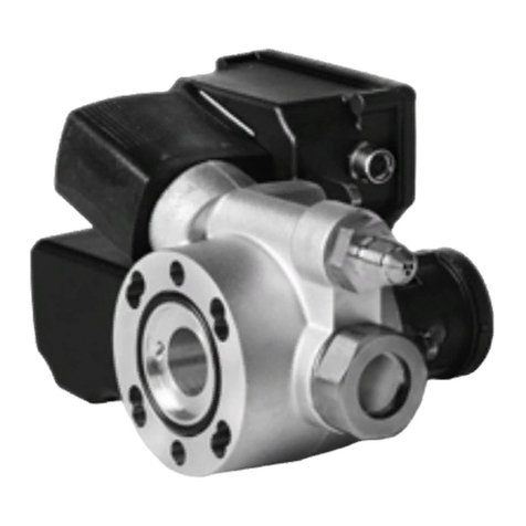
KRIWAN INT280 User manual

KRIWAN Oil level regulators
Operating Instructions Accessories
and Application Information

2/18 810.00113.0
Content
General information .................................................................................................................................................. 4
Manufacturer ..........................................................................................................................................4
Storage information ................................................................................................................................4
Supplementary documents .....................................................................................................................4
List of standards and directives applied ..................................................................................................4
Guarantee and liability ............................................................................................................................5
Updating ................................................................................................................................................5
Copyright ...............................................................................................................................................5
1 Safety Guidelines ...................................................................................................................................................... 6
1.1 Meaning of the symbols and safety instructions used in this document ...................................................6
1.2 General safety instructions ......................................................................................................................6
1.2.1 Due diligence of the operator ......................................................................................................6
1.2.2 Requirements for personnel ........................................................................................................7
1.3 Special types of danger ..........................................................................................................................7
1.3.1 Pneumatic dangers .....................................................................................................................7
1.3.2 Electrical dangers ........................................................................................................................7
1.3.3 Thermal dangers .........................................................................................................................7
1.3.4 Environmental sources of danger ................................................................................................7
2 Product Description .................................................................................................................................................. 8
2.1 Usage in the specified manner ................................................................................................................8
2.2 Reasonably foreseeable misuse ..............................................................................................................8
2.3 CE Declaration .......................................................................................................................................8
2.4 Application limits .....................................................................................................................................8
2.4.1 Mechanical limits .........................................................................................................................8
2.4.2 Energy limits ................................................................................................................................8
2.4.3 Temporal limits ............................................................................................................................8
2.4.4 Operator limitations .....................................................................................................................8
3 Transport and Storage .............................................................................................................................................. 8
4 Assembly ................................................................................................................................................................... 9
4.1 Safety instructions for the installation ......................................................................................................9
4.2 Preparation .............................................................................................................................................9
4.3 Electrical connection ...............................................................................................................................9
4.4 Installation ............................................................................................................................................10
4.4.1 Mechanical installation ...............................................................................................................10
4.4.2 Cable installation .......................................................................................................................10
4.4.3 DP cable connections ...............................................................................................................10
4.5 Before commissioning ..........................................................................................................................10
5 Functional description ............................................................................................................................................ 11
5.1 Application information .........................................................................................................................11
5.2 Refill intervals ........................................................................................................................................11
5.2.1 INT280 B ..................................................................................................................................11
5.2.2 "INT280-xxx" .............................................................................................................................11
5.2.3 "INT280-xxx" Diagnose .............................................................................................................12
5.3 Explanation of individual parameters .....................................................................................................12
6 Troubleshooting ...................................................................................................................................................... 13
7 Service .................................................................................................................................................................... 14
7.1 Inspection .............................................................................................................................................14
7.1.1 Function check ..........................................................................................................................14
7.2 Maintenance .........................................................................................................................................14
7.3 Cleaning ...............................................................................................................................................14
7.3.1 INT280 B ..................................................................................................................................14
7.3.2 "INT280-xxx" .............................................................................................................................14
8 Decommissioning and disassembly ........................................................................................................................ 15

810.00113.0 3/18
9 Disposal .................................................................................................................................................................. 15
10 Accessories ............................................................................................................................................................. 16
10.1 Adapter ................................................................................................................................................16
10.1.1 INT280 Adapter 1 1/8"- 12 UNF ................................................................................................16
10.1.2 INT280 Adapter 1 1/8"- 18 UNEF ..............................................................................................16
10.1.3 INT280 Adapter 3/4"- 14 NP .....................................................................................................17
10.1.4 INT280 Adapter 1 3/4"- 12 UNF ................................................................................................17
10.1.5 INT280 Adapter 1 1/4"-12 UNF .................................................................................................18
10.2 DP-Y Cable ..........................................................................................................................................18

4/18 810.00113.0
General information
Document: Operating Instructions Accessories and Application Information
Valid for: Product range oil level regulators
Document name: TB810.00113.0
Revision version R0217
Number of pages including title page: 18
Manufacturer
KRIWAN Industrie-Elektronik GmbH
Allmand 11
D-74670 Forchtenberg
Phone (+49) 7947 822 0
Fax (+49) 7947 1288
E-mail: [email protected]
Home: www.kriwan.com
Storage information
The operating company is obligated to store these operating instructions for accessories and application information
as well as the data sheet for everyone who is tasked with work on or with the system.
A missing document or missing pages need to be replaced promptly.
This document is available for download at www.kriwan.com.
Supplementary documents
In combination with this application information, the following documents and forms need to be observed:
•
The data sheet belonging to the oil level regulator
•
General or applications-specific operating instructions in the context of labor protection laws and regulations
relating to operating materials
•
Accident prevention guidelines
•
Legal provisions
•
Local provisions
List of standards and directives applied
See EU declaration of conformity

810.00113.0 5/18
Guarantee and liability
The "General Conditions of Sale and Delivery" of the manufacturer are valid as a matter of principle. They are
available to the customer at the latest when the contract is signed.
The manufacturer rules out warranty and liability claims in cases of personal and material damage if they can be
traced to one or several of the following causes:
•
Usage not in the specified manner
•
Improper installation, commissioning and application
•
Operation when safety systems are not properly attached or not functioning
•
Ignoring the safety instructions and information in these application instructions and in the data sheet
•
Unauthorized reconstructions and modifications
•
Improper or late maintenance
•
Accessories, spare parts, and additives that are the cause for damages and for which there are no releases from
the manufacturer
•
Catastrophic cases due to foreign objects and acts of nature beyond control
Updating
This document is not subject to updating by the manufacturer.
Changes in document can be carried out without further announcement.
The respective current version is available from the manufacturer.
Copyright
© KRIWAN Industrie-Elektronik GmbH
This documentation contains information protected by copyright. It may not be photocopied, duplicated, translated
or saved on data carriers wholly or in excerpts without previous authorization by the manufacturer.
The manufacturer reserves all further rights.

Safety Guidelines
6/18 810.00113.0
1 Safety Guidelines
1.1 Meaning of the symbols and safety instructions used in this document
This document contains information that must be observed to protect persons against injuries as well as to prevent
material damage.
The safety instructions to protect persons against injuries are highlighted by a signal panel with a warning triangle
and a signal word defined according to ANSI Z535.6-2006: A1.2.
The signal words are classified according to ANSI Z535.6-2006: C4.2.
Depending on the degree of exposure, the panels are displayed as following:
The text of safety instructions is organized in:
1.2 General safety instructions
Please note that the device is intended exclusively for the application range stated in this document or in the data
sheet. Any other or further usage is deemed as usage not in the specified manner.
Use the device
•
in the specified manner
•
in fault-free condition
•
while minding safety and dangers.
The device may be operated only in its specified performance limits (see Technical specifications).
Have malfunctions that may negatively affect the safety rectified immediately.
Only original parts of the manufacturer are approved as spare parts and accessories.
1.2.1 Due diligence of the operator
The operator is responsible for implementing a suitable safety concept and for procuring additional safety
equipment.
Please note that a safety symbol can never replace the text of safety instructions – the text of safety
instructions must therefore always be read completely.
Points marked with this symbol indicate that fatal or serious injuries will occur if the respective safety
precautions are ignored!
Points marked with this symbol indicate that fatal or serious injuries can occur if the respective safety
precautions are ignored!
Points marked with this symbol indicate that less serious injuries can occur if the respective safety
precautions are ignored!
Points marked with this symbol refer to further information and application hints. This symbol does
not indicate safety instructions.
Description of the type and source of danger
• Description of the consequences if safety instructions are ignored.
ÂPrecautions
Selection of suitable components
• Danger to the operational reliability
ÂOnly such components may be selected that are approved for the planned operating
condition.

Safety Guidelines
810.00113.0 7/18
1.2.2 Requirements for personnel
1.3 Special types of danger
1.3.1 Pneumatic dangers
1.3.2 Electrical dangers
1.3.3 Thermal dangers
1.3.4 Environmental sources of danger
Improper installation, commissioning or maintenance.
• Danger to the operational reliability.
ÂInstallation, commissioning and maintenance tasks may be carried out only by authorized
technicians.
ÂRead the operating instructions thoroughly. Non-adherence can cause the device to fail or
be destructed and can lead to injuries.
Danger of bursting
• Pressurised parts that burst can cause serious to fatal injuries.
ÂThe max. test pressure must not be exceeded.
Pressure in the compressor
• Working on pressurised parts can cause serious to fatal injuries.
ÂWork on the pneumatic equipment may only be carried out by refrigeration technicians.
ÂDepressurise the respective part of the system before installation or disassembly.
Electric shock
• Touching live parts can lead to serious to fatal injuries.
ÂWork on the electric equipment may only be carried out by electricians, taking into account
the information specified in the Technical specifications chapter.
ÂThe applicable European and national standards for connecting electrical equipment must
be observed.
ÂThe voltage supply to the oil level regulator has to be switched off prior to connection/
installation and the subsequent tasks.
ÂMaintain the operating voltage specified on type plate.
Overheating
• Fire due to overheating
ÂMaintain temperatures within the specified limits.
Electric ignition sources
• Explosion due to electric ignitions of an explosive atmosphere.
ÂThe device must not be operated in an explosive atmosphere.
Electric ignition sources
• Fire due to overheating.
ÂThe device must not be operated in flammable areas.

Product Description
8/18 810.00113.0
2 Product Description
2.1 Usage in the specified manner
The oil level regulator monitors and controls the oil level in the refrigerant compressors.
Details can be found in the corresponding data sheet.
The INT280 adapters (see Chapter Accessories) serve to connect the oil level regulator to refrigerant compressors.
The necessity and possibly the selection of an adapter are determined by the design of the sight glass of the
refrigerant compressor.
Special specifications on usage in the specified manner:
•
The KRIWAN oil level regulators may be operated only within their specified performance limits (see Technical
specifications chapter of the respective data sheet).
•
Observing the installation instructions and following the maintenance and repair regulations are a prerequisite for
use in the specified manner.
•
Any other or further usage is deemed as usage not in the specified manner.
2.2 Reasonably foreseeable misuse
•
Operation in potentially explosive areas is not permitted.
•
Operation in flammable areas is not permitted.
•
Modifications to the device are not permitted.
•
Spare parts or accessories not supplied by the manufacturer are not permitted because they have not been
tested for the operation and they may negatively affect operational safety.
2.3 CE Declaration
The valid CE Declaration can be requested from the manufacturer.
2.4 Application limits
2.4.1 Mechanical limits
Mechanical limits according to drawing and technical data on the separate data sheet or in the description of the
accessories of this document.
2.4.2 Energy limits
Electrical: Connection specifications refer to separate data sheet.
2.4.3 Temporal limits
Until shut-down.
2.4.4 Operator limitations
3 Transport and Storage
The manufacturer assumes no liability for damages caused by misuse.
Normal mode: trained personnel
Maintenance / Repair: trained, qualified personnel
Soiling of the oil level regulator, in particular the oil connections.
• Soiling can cause malfunctions.
ÂTransport and storage only in the original transport packaging or in a suitable individual
packaging.

Assembly
810.00113.0 9/18
4 Assembly
4.1 Safety instructions for the installation
4.2 Preparation
•
Prior to installation, ensure that the O-ring at the connecting flange is seated properly.
•
There must be no foreign objects in the oil infeed or outfeed area of the Ölspiegelregulators.
•
The device has to be mounted to the compressor horizontally. It can be rotated by 180°.
•
Use matching washers for the flange fastening screws.
•
For use at low temperatures, an oil sump heater has to be installed, to ensure trouble-free operation of the
Ölspiegelregulators.
•
An oil filter has to be installed in the oil infeed line of the Ölspiegelregulators, to prevent the solenoid valve seat
from getting dirty.
4.3 Electrical connection
•
The electrical connection is carried out according to the respective wiring diagrams, which are part of the
corresponding data sheets.
•
For the 115V and 24V versions, ensure that the correct supply voltage is used.
Danger of bursting
• Pressurised parts that burst can cause serious to fatal injuries.
ÂThe max. test pressure must not be exceeded.
Pressure in the compressor
• Working on pressurised parts can cause serious to fatal injuries.
ÂWork on the pneumatic equipment may only be carried out by refrigeration technicians.
ÂDepressurise the respective part of the system before installation or disassembly.
Electric shock
• Touching live parts can lead to serious to fatal injuries.
ÂWork on the electric equipment may only be carried out by electricians, taking into account
the information specified in the Technical specifications chapter.
ÂThe applicable European and national standards for connecting electrical equipment must
be observed.
ÂThe voltage supply to the oil level regulator has to be switched off prior to connection/
installation and the subsequent tasks.
ÂMaintain the operating voltage specified on type plate.
Soiling of the oil level regulator, in particular the oil connections.
• Soiling can cause malfunctions.
ÂInstallation must be carried out without soiling.
Separate isolation switches are necessary for the KRIWAN oil level regulators.

Assembly
10/18 810.00113.0
4.4 Installation
4.4.1 Mechanical installation
1. Pre-assemble the oil level regulator in the mounting position.
2. Screw in screws by hand.
3. Then tighten with 9Nm tightening torque.
Additionally for the installation of an adapter:
1. Ensure the cleanliness of the thread of the compressor and adapter.
2. Assemble the INT280 adapter so that the hexagon of the inner part is flush mounted with the outer ring (see
note A in dimensions in mm in the Accessories chapter).
3. Mount the thus pre-assembled INT280 adapter to the compressor with the specified torque of the manufacturer.
4. Mount the INT280 oil level regulator with sealing ring to the adapter; mounting the screws hand-tight with the
included washers. Then tighten with 9Nm tightening torque.
4.4.2 Cable installation
Observe the following points when routing the connecting cables:
•
Do not go below the bending radius permitted for the cable used.
•
Fixate the cable suitably at sufficient distances.
•
Route the cable with drip loop.
•
The seal of the PG screw fittings is ensured only when approved cable cross-sections are used (see data sheet).
4.4.3 DP cable connections
•
The "INT280-xxx" Diagnose can operate with the data of the compressor protection units INT69 Diagnose.
Coupling is by a DP-Y cable (see Accessories).
•
If there is a network with an INT600 DM, only original DP cables from KRIWAN may be used.
•
DP cables may not be modified or extended.
•
If no DP cable is connected, then the DP protection needs to be mounted.
•
DP cables may only be connected or disconnected when there is no voltage.
4.5 Before commissioning
•
Before the oil level regulator is switched on for the first time, the oil level should already be at ¼ of the sight glass
to prevent the alarm relay from being deactivated.
•
Before the refrigerating system is filled with refrigerant, the system and the connections of the Ölspiegelregulators
have to be checked for leaks.
The oil level regulator has to be installed in such a way that the sight glass points to the left or to the
right. Only the horizontal installation according to the data sheet is in the specified manner and thus
permitted.

Functional description
810.00113.0 11/18
5 Functional description
5.1 Application information
5.2 Refill intervals
5.2.1 INT280 B
After the INT280 B is switched on, the alarm relay picks up after 3s, if no malfunction is present (closed-circuit
principle). Regardless of the oil level, a 20 second pause is activated to allow the oil to settle. If, thereafter, a too low
oil level is detected, the solenoid valve switches to oil injection in a specified cycle:
1st cycle: fill 5s / wait 5s,
2nd cycle: fill 10s / wait 10s,
3rd cycle: fill 20s / wait 20s...
If, after 135s, an adequate oil level has not been reached, the alarm relay drops out. The last filling cycle that has
been reached (fill approx. 30s and wait approx. 30s) stays active. If an adequate oil level has been reached, the
alarm relay picks up again after a waiting time, the filling cycle is reset.
If there is a device malfunction (e.g. low supply voltage), the alarm relay drops out and is locked, regardless of the
oil level, after approx. 5s. No filling procedure is performed.
The lock can be released by an open circuit of the voltage supply for at least 5s.
5.2.2 "INT280-xxx"
After the "INT280-xxx" is switched on, the alarm relay picks up after 3s, if no malfunction is present (closed-circuit
principle). Regardless of the oil level, a 2 second pause is activated, to allow the oil to settle. If, thereafter, a too low
oil level is detected, the solenoid valve switches to oil injection for the filling time (default 10s).
If the fill level has not been reached until then, the solenoid valve is switched off for the break time (default 20 % =
2s) and then switched back on for the filling time. This is continued until the fill level is reached.
If an adequate oil level has not been reached after the oil deficiency alarm delay has expired (default 120s), the alarm
relay drops out. Refilling oil is continued to be attempted. If an adequate oil level has been reached, the alarm relay
picks up again after a waiting time.
If there is a device malfunction (e.g. low supply voltage), the alarm relay drops out and is locked, regardless of the
oil level, after approx. 5s. No filling procedure is performed.
The "INT280-xxx" has its own monitoring system of the optical sensor. If there is a malfunction, the alarm relay is
locked and the error is signalled by the flash code.
If there is a soiling of the glass cone, this is signalled by the flash code when the warning threshold is exceeded. The
function continues to be ensured.
A cleaning should be carried out during the next general maintenance, see Chapter Cleaning.
If the soiling of the glass cone reaches a critical value, the compressor is switched off locked or the warning soiling
stage 2 is generated, depending on the setting.
The lock can be released by an open circuit of the voltage supply for at least 5s.
For proper operation, make sure that there is always enough oil in the oil reservoir and sufficient oil
pressure is available.
If there is a malfunction in the refrigeration circuit, in particular in cases where foreign particles, e.g.
soot, may get into the oil circuit, the oil and the corresponding filters need to be replaced. The oil
level regulator also needs to be replaced in case a cleaning of the prism of the oil level regulator
cannot be done.
The applications and the functional description are specified in the accompanying data sheet.

Functional description
12/18 810.00113.0
5.2.3 "INT280-xxx" Diagnose
By means of the diagnose port, data such as the last 20 errors, error counters, current status and switching
behaviours can be read out with the INTspector.
A variety of parameters to be adjusted for optimal adaption to the application. Refer to the data sheet on which
parameters these are.
5.3 Explanation of individual parameters
Parameter name
Filling cycle type With "fixed", the filling cycle runs with the set filling and break time. If the filling
cycle type is switched to "adaptive", the "INT280-xxx" calculates the optimal
filling and break times itself. The times are calculated so that the set nominal
filling period number is calculated.
Filling time Time that the solenoid valve is opened cyclically if there is an oil deficiency.
Break time Time that the solenoid valve is closed cyclically if there is an oil deficiency. The
time is specified in percent of the filling time.
Overfill time Once the fill level of the oil has been reached, the solenoid valve remains open
for the time set here.
Set number of filling periods With "adaptive" control, the oil level regulator calculates the times so that this
number of filling times is needed until the filling.
Oil deficiency alarm monitoring A choice can be made here whether the alarm delay of the compressor run
should be evaluated or not.
Oil deficiency alarm delay If a deficiency of oil is detected, this time is started. Once the time has elapsed,
the relay switched the compressor off. If the function "Alarm monitoring only
when compressor is running" is active, the time is stopped when the
compressor is at standstill. Once the compressor starts up again, it continues
to run.
External alarm via DP bus When the Diagnose devices are connected, a choice can be made here whether
an alarm from a different Diagnose device will also cause the alarm relay of the
oil level regulator to be switched off and that the alarm is displayed at the LED
of the oil level regulator.
Operating recognition via DP bus A setting can be made here whether the run detection should be evaluated or
not of a connected Diagnose compressor protection unit.
Behaviour monitoring A setting can be made here whether the behaviour monitoring should be active
or not.
Filling cycle time overrun coefficientWhen the DP bus run detection is active, the oil level regulator determines an
average filling cycle time. If this time is exceeded during a filling process for the
coefficient set here, a warning is generated.
Time overrun without filling
coefficient
When the DP bus run detection is active, the oil level regulator determines an
average time without filling process. If this time is exceeded during compressor
run for the coefficient set here, a warning is generated.
Soiling stage 2 The glass cone is monitored for soiling. A choice can be made here whether the
compressor should be switched off if the second soiling stage is exceeded.
too low
good
open
closed
Oil level
Solenoid valve
Filling time Break time Filling time Filling
Break time Overfill
Filling period
Filling cycle
time
time

Troubleshooting
810.00113.0 13/18
6 Troubleshooting
Malfunction Possible cause Solution
Oil level in the compressor too low
even if there is refilling
No oil in the oil reservoir Refill oil, find oil imbalance
Oil level in the compressor too low
even if there is refilling
Differential pressure is too low Check whether the differential
pressure between oil reservoir and
compressor is great enough; set
differential pressure valve.
Compressor is running even though
there is not enough oil in the
compressor for a longer time.
Alarm relay not in the alarm chain Correct the connection
Alarm relay pulls in even though
compressor is at standstill
No filling possible due to missing inlet
pressure
Use "INT280-xxx" Diagnose (run
detection possible and thus no alarm
when compressor at standstill)

Service
14/18 810.00113.0
7 Service
7.1 Inspection
7.1.1 Function check
If the application is being inspected for other reasons, the following points can be checked:
1. Is the oil level regulator complete and mechanically undamaged?
•
Replace oil level regulator if necessary.
2. Is the sight glass filled up to half?
•
See Chapter Malfunctions and Troubleshooting.
3. Is the oil level regulator still properly mounted; are the connections sealed?
•
Tighten the mounting screws if necessary.
7.2 Maintenance
7.3 Cleaning
7.3.1 INT280 B
7.3.2 "INT280-xxx"
1. Switch the system free of voltage.
2. Evacuate the refrigerant compressor.
3. Depressurise oil connection.
4. Remove the oil level regulator.
5. Clean the glass prim with a soft cloth.
KRIWAN oil level regulators are maintenance-free and therefore there are no fixed inspection
intervals specified for them.
The device is maintenance-free.
Replace the oil level regulator if there is a malfunction.
No special cleaning measures necessary.
The oil level regulator cannot be cleaned at the parts that determine the function.
Replace the oil level regulator if there is a malfunction.
If the oil level regulator signals that it is soiled, it can be removed and the glass prism can be cleaned
with a soft cloth.
Electric shock
• Touching live parts can lead to serious to fatal injuries.
ÂWork on the electric equipment may only be carried out by electricians.
ÂDisconnect the current from the respective part of the system before the disassembly.
Pressure in the compressor
• Working on pressurised parts can cause serious to fatal injuries.
ÂWork on the pneumatic equipment may only be carried out by refrigeration technicians.
ÂDepressurise the respective part of the system before installation or disassembly.

Decommissioning and disassembly
810.00113.0 15/18
8 Decommissioning and disassembly
1. Switch the system free of voltage.
2. Evacuate the refrigerant compressor.
3. Depressurise oil connection.
4. Remove the oil level regulator.
5. Close the opening on the compressor with the original sight glass and close the oil level regulator with the original
covers.
9Disposal
All corresponding components have to be disposed of according to national recycling regulations.
Valid in Germans is for example:
Electric shock
• Touching live parts can lead to serious to fatal injuries.
ÂWork on the electric equipment may only be carried out by electricians.
ÂDisconnect the current from the respective part of the system before the disassembly.
Pressure in the compressor
• Working on pressurised parts can cause serious to fatal injuries.
ÂWork on the pneumatic equipment may only be carried out by refrigeration technicians.
ÂDepressurise the respective part of the system before installation or disassembly.
Electrical scrap metal
Devices marked with this symbol are subject to the European directive 2002/96/EU.
All waste electronic and electrical equipment needs to be disposed of separately from household
garbage. Check with your local municipal authorities (local government, town hall) on how to dispose
of your waste equipment in an environmentally safe way.

Accessories
16/18 810.00113.0
10 Accessories
10.1 Adapter
10.1.1INT280 Adapter 1 1/8"- 12 UNF
Order data
Technical specifications
Dimensions in mm
INT280 Adapter 1 1/8"- 12 UNF 02 K 500 S21
38
20
7.5
Ø 47.6
A
124° 124°
A=max. 1
Ø62
Ø25
11/8"-12 UNEF
WS38
23
3x M6
Permitted ambient
temperature
-30…+100°C
Permitted rel. humidity 10-95% RH, without
condensation
Operating pressure max. 140bar
Test pressure max. 210bar
Connection thread 1 1/8" - 12 UNF
Flange mounting
- Screws M6x20 Class 8.8 DIN 933
- Washer DIN EN ISO 7089-6-St
- Toothed gear DIN 6798-A 6.4-FSt
- Seal EPDM
- Tightening torque 9Nm
Material Steel, nickel-plated
Permissible media Oils and refrigerant that do not
attack the material of the
adapter.
Dimensions See dimensions in mm
Weight Approx. 300g
10.1.2INT280 Adapter 1 1/8"- 18 UNEF
Order data
Technical specifications
Dimensions in mm
INT280 Adapter 1 1/8"- 18 UNEF 02 K 502 S21
27
11
7
Ø 47.6
A
124° 124°
A=max. 1
Ø62
1
1
/
8
"-18 UNEF
WS38
3x M6
Permitted ambient
temperature
-30…+100°C
Permitted rel. humidity 10-95% RH, without
condensation
Operating pressure max. 140bar
Test pressure max. 210bar
Connection thread 11/8"-18UNEF
Flange mounting
- Screws M6x20 Class 8.8 DIN 933
- Washer DIN EN ISO 7089-6-St
- Toothed gear DIN 6798-A 6.4-FSt
- Seal EPDM
- Tightening torque 9Nm
Material Steel, nickel-plated
Permissible media Oils and refrigerant that do not
attack the material of the
adapter.
Dimensions See dimensions in mm
Weight Approx. 300g

Accessories
810.00113.0 17/18
10.1.3INT280 Adapter 3/4"- 14 NP
Order data
Technical specifications
Dimensions in mm
INT280 Adapter 3/4"- 14 NPT 02 K 503 S21
34
19
15
Ø 47.6
A
124°124°
A=max. 1
Ø62
Ø25.67
WS38
3x M6
Permitted ambient
temperature
-30…+100°C
Permitted rel. humidity 10-95% RH, without
condensation
Operating pressure max. 140bar
Test pressure max. 210bar
Connection thread 3/4" - 14 NPT
Flange mounting
- Screws M6x20 Class 8.8 DIN 933
- Washer DIN EN ISO 7089-6-St
- Toothed gear DIN 6798-A 6.4-FSt
- Seal EPDM
- Tightening torque 9Nm
Material Steel, nickel-plated
Permissible media Oils and refrigerant that do not
attack the material of the
adapter.
Dimensions See dimensions in mm
Weight Approx. 300g
10.1.4INT280 Adapter 1 3/4"- 12 UNF
Order data
Technical specifications
Dimensions in mm
INT280 Adapter 1 3/4"- 12 UNF 02 K 504 S21
42
20
11.8
Ø 47.6
Ø 26
A
124°
124°
A=max. 1
Ø62
1
3
/
4
"-12 UNEF
WS38
WS50
3x M6
Permitted ambient
temperature
-30…+100°C
Permitted rel. humidity 10-95% RH, without
condensation
Operating pressure max. 140bar
Test pressure max. 210bar
Connection thread 1 3/4" - 12 UNF
Flange mounting
- Screws M6x20 Class 8.8 DIN 933
- Washer DIN EN ISO 7089-6-St
- Toothed gear DIN 6798-A 6.4-FSt
- Seal EPDM
- Tightening torque 9Nm
Material Steel, nickel-plated
Permissible media Oils and refrigerant that do not
attack the material of the
adapter.
Dimensions See dimensions in mm
Weight Approx. 300g

10.1.5INT280 Adapter 1 1/4"-12 UNF
Order data
Technical specifications
Dimensions in mm
INT280 Adapter 1 1/4"-12 UNF 02 K 505 S21
36
12
6.3
Ø 47.6
Ø 20
A
124°
124°
A=max. 1
Ø62
11/4"-12 UNEF
WS38
WS36
3x M6
Permitted ambient
temperature
-30…+100°C
Permitted rel. humidity 10-95% RH, without
condensation
Operating pressure max. 140bar
Test pressure max. 210bar
Connection thread 1 1/4" - 12 UNF
Flange mounting
- Screws M6x20 Class 8.8 DIN 933
- Washer DIN EN ISO 7089-6-St
- Toothed gear DIN 6798-A 6.4-FSt
- Seal EPDM
- Tightening torque 9Nm
Material Steel, nickel-plated
Permissible media Oils and refrigerant that do not
attack the material of the
adapter.
Dimensions See dimensions in mm
Weight Approx. 300g
10.2 DP-Y Cable
Order data
DP-Y cable 600V FK02098076
KRIWAN Industrie-Elektronik GmbH
Allmand 11 · D-74670 Forchtenberg
phone (+49) 7947 822 0 · fax (+49) 7947 1288
Table of contents
Other KRIWAN Controllers manuals