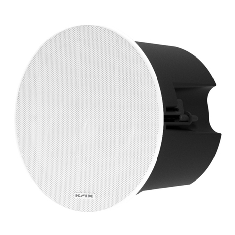
Krix IC-30 User manual

IC-30, IC-32 &IC-35S
INSTALLATION GUIDE

Figure 3
Figure 4
Figure 2
500mm
recommended
minimum
A20 Orientation
500mm
Figure 1
SETUP IN BRIEF
The following setup procedure will help you gain the best
performance from your in-ceiling speaker:
1. Unpacking
Remove your speaker from the packaging
2. Introduction
Learn about the IC-30, IC-32 and IC-35S
3. Before you begin
Determine a suitable location for your speakers
4. Installation
Cut mounting hole, connect cabling and install speaker
5. Listen and enjoy
Listen to your favourite music/movies and enjoy
Disclaimer
Drilling into anything can be dangerous. You should make sure you know what is behind or inside the surface that you are drilling before
you start to drill. For example, you might strike an electrical cable.
You must install the speaker securely to the surface that you are xing it to. If you don’t, injury or damage may occur.
If you do not feel entirely condent about installing this product, contact a professional installer.
To the extent permissible by law:
All warranties, conditions, representations, promises and statements relating howsoever to this product whether express or implied and
whether in contract or tort are excluded to the extent permitted by law; and
Our liability to you under a condition or warranty (if any) implied into this sale and purchase agreement relating to these brackets by the
Trade Practices Act 1974 (as amended) or any other law (whether a law of Australia or any other country) other than a condition implied by
Section 69 of the said Act is limited at our option to:
the replacement of the product; or
the supply of an equivalent product; or
the repair of the product.
If you do not accept the above conditions, return this product (in the original packaging) with proof of purchase for a full refund.
INTRODUCTION
Congratulations on choosing Krix
Your Krix speakers are designed to reproduce the highest quality sound. To get the best
performance from your speakers please read these installation instructions thoroughly as
there are many factors that influence the performance of your speakers. If you have any
difculties please contact one of our friendly authorised Krix dealers.
Introduction
The IC-30 and IC-32 are in-ceiling loudspeakers
featuring fully sealed back-boxes to control and
maximise bass response, whilst keeping out
dust and other ceiling inhabitants.
The IC-32 employs an acoustically optimised
front baffle angled at 20 degrees, allowing its
sound output to be projected towards your
primary listening area.
The IC-30 employs a flat front baffle for uniform
sound coverage in all directions
The IC-35S features a stereo pair of inputs and
a slim semi-open back box, providing a stero
effect from a single source (gure 1).
Applications best suited to IC-30
The wide uniform coverage of the IC-30 makes
it the ideal choice for 2 channel stereo and
background music applications. Its uniform
coverage is ideally suited to any applications
where the listening area is not conned to a
specic part of the room. For example, hallways,
dining rooms, ofce spaces, bedrooms and
multipurpose rooms (gure 2).
Applications best suited to IC-32
The ability of the IC-32 to project sound toward
your primary listening area makes it ideally
suited to home cinema applications (gure 3).
Dialogue will become more articulate, music
will have better denition and surround effects
will become more involving and realistic. The
IC-32’s ability to direct more sound towards
the listener results in less sound reflecting
off walls and other surfaces in the room,
creating a clearer, more three dimensional
soundstage. The IC-32 may also be useful
for background music applications where
the speaker must be placed near a side wall
for aesthetic or structural reasons. In this
application the IC-32 can be used to project
the sound towards the centre of the room.
Applications best suited to IC-35S
The IC-35S is perfect in small rooms where there
is difculty tting a stereo pair of loudspeakers
(gure 4). It can also be used where there is
limited ceiling height.
If desired, two IC-35S loudspeakers may be
wired together in parallel, or a single IC-35S
may have both inputs wired in parallel from a
single output.
IC-32
IC-32
IC-35S
IC-30
157 145 90
IC-30 IC-35S
2 3

Figure 13
Figure 10 Figure 11
Figure 12
Figure 9Figure 8
• Also ensure that there is enough ceiling/
wall space to accommodate the speaker
enclosure.
Connecting
To ensure optimum performance, it is
important that your speaker system is
connected properly:
Turn off all electronic equipment and
disconnect from the power point.
• Follow the connection instructions
supplied with your amplier and media
player.
• Install speaker cable in the wall or the
ceiling cavity. Allow approximately
300mm of excess cable to facilitate the
loudspeaker installation.
• Follow the connection instructions
supplied with your amplier to connect
the speaker cables to amplier. Take
care to assign the same cable colour or
trace to the positive (+) connector on the
amplier as the positive (+) connector on
the speaker.
• Prepare the speaker cables for connecting
to speakers by neatly stripping the cable
ends.
Care should be taken to eliminate loose
strands of wire that may present a short
circuit hazard.
Painting
• If the speaker grille requires painting it is
recommended to use a spray can for ease
of application. Alternatively, it is possible
to apply acrylic or enamel paint using a
small foam roller but this will require more
applications to achieve a good result.
Spray can application
• Use a spray can to apply a light coat of
paint. Rotate the product at 90° intervals
and apply three more light coats to ensure
an even coverage (gure 6).
• Be careful in applying single heavy coats
of paint as there is a higher probability
of blocking the holes in the grille. If the
grill does become blocked by paint,
use a small pin or similar to release the
blockage, while the paint is still wet.
Roller application
• Load a foam roller with a light coverage
of thin paint and then roll onto the grille.
Try to avoiding blocking the holes in the
grille. If the grille does become blocked
by paint, use a small pin or similar to
release the blockage, while the paint is
still wet.
• Allow the paint to dry. Apply three or more
light coats to ensure an even coverage
(gure 7).
Installation
• Once the correct placement has been
determined, use the cardboard insert
marked ‘template’ (from the internal
packing) to trace the required cut-out
onto the ceiling/wall (gure 8).
• Drill a hole inside the marked cut-out.
Using a ne gyprock saw, cut around the
inside of the marked cut-out (gure 9).
• Remove the circular offcut and insert the
speaker to check the hole is the correct
size. Enlarge the cut-out if required.
IC-32 only:
Determine the correct orientation for
your speaker. It is recommended that
the Krix logo is aimed towards your
primary listening area for best results
(gure 3).
• Pull the stripped speaker cable through
the ceiling/wall opening. Push and hold
down the positive (+) red binding post on
the speaker and insert the positive (+) wire
through the hole in the post. Take care to
assign the same cable colour or trace to
the positive (+) connector on the amplier,
as the positive (+) connector on the
speaker. Repeat the connection process
with the negative (-) black binding post
and the negative (-) wire (gure 10).
• Ensure all the mounting clamps are turned
back against the speaker enclosure
(gure 10), so that the speaker can be easily
inserted into the ceiling cut-out. Once the
speaker has been located in the ceiling/
wall, use a Phillips head screwdriver to
tighten all the mounting screws. As the
screws are tightened, the mounting
clamps will automatically swing out over
the plaster board and clamp the speaker
in place. Be careful not to overtighten the
screws, as this may strip the clamp, or
crush the plaster board surface (gure 11).
• The IC-30 features a pivoting tweeter
which allows the high frequency sound to
be directed as desired. Gently press on the
round outer edge of the tweeter frame to
tilt the tweeter to the desired position. Be
careful not touch the tweeter diaphragm,
as this may damage the tweeter (gure 12).
• Gently t the magnetic grille to the front
of the speaker housing (gure 13).
INSTALLATION
Before you begin
Please read the disclaimer on page 2 of
this manual.
• To determine the best location for your
loudspeakers, refer to page 3 of this
manual and discuss with your local Krix
dealer, or installation consultant. Be sure
to check for any obstructions, such as
electrical wiring, plumbing, stud work or air
conditioning ducts before commencing
the installation (gure 5).
4
INSTALLATION
5
!
Figure 5
Figure 6
Figure 7
!
!
!
!

6 7
SPECIFICATIONS SPECIFICATIONS
Warranty
Lifetime limited warranty applies to the
cabinet and speaker.
(Refer to the details on the warranty card
supplied)
Queries
If you have any queries regarding the
Hemispherix or any other Krix product,
please contact your nearest Krix dealer or Krix
directly. Contact details are on the back cover
of this booklet.
IC-30 IC-35S
IC-32
Frequency range 65Hz - 40kHz in room response
Power handling 20-100 watts RMS recommended amplier power
Sensitivity 86dB for 2.83 volts at 1 metre
Conguration 2-way
Bass Driver(s) Nominal 100mm (4”) doped paper cone. 25mm (1”) voice coil
wound on high temperature Kapton former
Tweeter 20mm (¾”) ring radiator, adjustable ‘eyeball’
Crossover Points 2.1kHz
Impedance Nominally 6 ohms (minimum 4.2 ohms)
Enclosure Type Bass reflex, front vented
Dimensions 255mm diameter x 145mm mounting depth
Mounting cut-out diameter 207mm
Finish White (can be painted to match your décor)
Input Terminals Push type connectors
Weight 2kg each
Frequency range 70 Hz - 40 kHz in room response
Power handling 5-50 watts RMS recommended amplier power per channel
Sensitivity 85 dB for 2.83 volts at 1 metre
Conguration Dual 2-way
Bass Driver(s) 1 x 125mm (5”) polypropylene cone, 35mm dual voice coil
Tweeter 2 x 20mm (¾”) ring radiator
Crossover Points 2.4 kHz
Impedance Nominally 8 ohms per channel (Minimum 6.4 ohms)
Enclosure Type Semi-open back
Dimensions 255mm diameter x 90mm mounting depth
Mounting cut-out diameter 207mm
Finish White (can be painted to match your décor)
Input Terminals Push type connectors
Weight 1.8 kg each
Frequency range 65Hz - 40kHz in room response
Power handling 20-100 watts RMS recommended amplier power
Sensitivity 86dB for 2.83 volts at 1 metre
Conguration 2-way with 20° angle
Bass Driver(s) Nominal 100mm (4”) doped paper cone. 25mm (1”) voice coil
wound on high temperature Kapton former
Tweeter 20mm (¾”) ring radiator
Crossover Points 2.1kHz
Impedance Nominally 6 ohms (minimum 4.2 ohms)
Enclosure Type Bass reflex, front vented
Dimensions 255mm diameter x 157mm mounting depth
Mounting cut-out diameter 207mm
Finish White (can be painted to match your décor)
Input Terminals Push type connectors
Weight 2kg each

krix.com
Krix Loudspeakers Pty Ltd
14 Chapman Road
Hackham SA 5163
Australia
T 61 8 8384 3433
F 61 8 8384 3419
This manual suits for next models
2
Table of contents
Other Krix Speakers manuals

Krix
Krix Hemispherix AS User manual

Krix
Krix ATMOSPHERIX AS User manual

Krix
Krix HELIX User manual

Krix
Krix ESOTERIX ALTUM User manual

Krix
Krix Aquatix User manual

Krix
Krix symmetrix User manual

Krix
Krix Stratospherix User manual

Krix
Krix HEMISPHERIX A20 User manual

Krix
Krix IW-30 User manual

Krix
Krix Quatrix KX-5972 User manual