KROHNE OPTIFLEX 3200 C User manual

OPTIFLEX 3200 C/F
OPTIFLEX 6200 C/F
OPTIFLEX 7200 C/F/S
OPTIFLEX 8200 C/F/S/D
Supplementary Instructions for IECEx applications
Supplementary Instructions for IECEx applicationsSupplementary Instructions for IECEx applications
Supplementary Instructions for IECEx applications
OPTIFLEX X200
OPTIFLEX X200OPTIFLEX X200
OPTIFLEX X200 Supplementary Instructions
Supplementary InstructionsSupplementary Instructions
Supplementary Instructions
© KROHNE 09/2018 - 4006564001 - AD IECEX OPTIFLEX x200 R01 en

CONTENTS
2
www.krohne.com 09/2018 - 4006564001 - AD IECEX OPTIFLEX x200 R01 en
OPTIFLEX X200
1 General safety information 4
1.1 Scope of the document..................................................................................................... 4
1.2 Device description ............................................................................................................ 4
1.3 Standards and approvals.................................................................................................. 4
1.4 Equipment protection levels (EPL)................................................................................... 5
1.4.1 Ex ia-approved devices ........................................................................................................... 5
1.4.2 Ex ia/db- and Ex ia/tb-approved devices ................................................................................ 6
1.4.3 Ex ic devices ............................................................................................................................ 8
1.4.4 Ex ic nA devices....................................................................................................................... 9
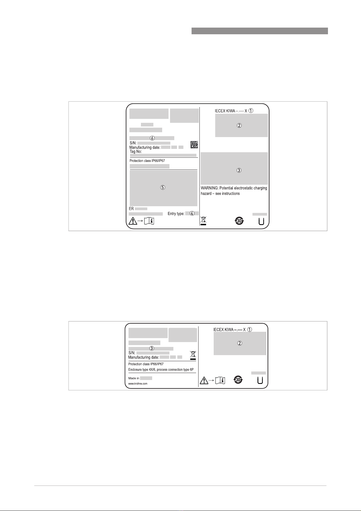
1.5 IECEx nameplates .......................................................................................................... 10
2 Installation 11
2.1 Special conditions........................................................................................................... 11
2.2 Precautions..................................................................................................................... 11
2.2.1 General notes........................................................................................................................ 11
2.2.2 Electrostatic discharge......................................................................................................... 11
2.3 Operating conditions: ambient and process connection temperatures........................ 12
2.3.1 General notes........................................................................................................................ 12
2.3.2 OPTIFLEX 3200 C (compact converter version).................................................................... 13
2.3.3 OPTIFLEX 3200 F (remote converter version) ...................................................................... 14
2.3.4 OPTIFLEX 6200 C (compact converter version).................................................................... 15
2.3.5 OPTIFLEX 6200 F (remote converter version) ...................................................................... 17
2.3.6 OPTIFLEX 7200 C (compact converter version).................................................................... 18
2.3.7 OPTIFLEX 7200 C (compact) converter: replacement for the OPTIFLEX 1300 C converter 21
2.3.8 OPTIFLEX 7200 F (remote converter version) ...................................................................... 23
2.3.9 OPTIFLEX 7200 S (compact converter with sensor extension version) ............................... 25
2.3.10 OPTIFLEX 7200 D (remote converter with sensor extension version) ............................... 27
2.3.11 OPTIFLEX 8200 C (compact converter version).................................................................. 29
2.3.12 OPTIFLEX 8200 F (remote converter version) .................................................................... 32
2.3.13 OPTIFLEX 8200 S (compact converter with sensor extension version) ............................. 36
3 Electrical connections 38
3.1 General notes ................................................................................................................. 38
3.2 Terminal compartment .................................................................................................. 38
3.2.1 How to open the terminal compartment .............................................................................. 38
3.2.2 How to close the terminal compartment ............................................................................. 39
3.3 Terminal tightening capacity.......................................................................................... 40
3.4 Output options: terminals .............................................................................................. 41
3.4.1 One current output: 4...20 mA passive - HART..................................................................... 41
3.4.2 Two current outputs: 4...20 mA passive - HART + 4...20 mA passive .................................. 42
3.4.3 One current output and one switch output: 4...20 mA passive - HART + switch output (relay)
... ..................................................................................................................................................... 42
3.4.4 Modbus RTU .......................................................................................................................... 43
3.4.5 FOUNDATION™ fieldbus or PROFIBUS PA........................................................................... 43
3.5 Equipotential bonding system........................................................................................ 44

CONTENTS
3
www.krohne.com09/2018 - 4006564001 - AD IECEX OPTIFLEX x200 R01 en
OPTIFLEX X200
3.6 Ex ia equipment .............................................................................................................. 45
3.6.1 How to connect the electrical cables ................................................................................... 45
3.6.2 Maximum intrinsically-safe values for the electrical circuit ............................................... 45
3.6.3 Supply voltage ....................................................................................................................... 46
3.7 Ex ia/db and Ex ia/tb equipment .................................................................................... 46
3.7.1 General notes........................................................................................................................ 46
3.7.2 How to connect the electrical cables ................................................................................... 47
3.7.3 Supply voltage ....................................................................................................................... 48
3.8 Ex ic equipment .............................................................................................................. 49
3.8.1 How to connect the electrical cables ................................................................................... 49
3.8.2 Maximum intrinsically-safe values for the electrical circuit ............................................... 50
3.8.3 Supply voltage ....................................................................................................................... 50
3.9 Ex ic nA equipment......................................................................................................... 51
3.9.1 How to connect the electrical cables ................................................................................... 51
3.9.2 Supply voltage ....................................................................................................................... 52
4 Start-up 53
5 Service 54
5.1 Periodic maintenance..................................................................................................... 54
5.2 Keep the device clean..................................................................................................... 54
5.3 How to remove the device .............................................................................................. 54
5.4 OPTIFLEX 2200: Replacement of the signal converter.................................................. 55
5.5 OPTIFLEX 1300: Replacement of the signal converter.................................................. 55
5.6 Manufacturer.................................................................................................................. 56
5.7 Returning the device to the manufacturer..................................................................... 56
5.7.1 General information.............................................................................................................. 56
5.7.2 Form (for copying) to accompany a returned device............................................................ 57
6 Notes 58

1
GENERAL SAFETY INFORMATION
4
OPTIFLEX X200
www.krohne.com 09/2018 - 4006564001 - AD IECEX OPTIFLEX x200 R01 en
1.1 Scope of the document
These instructions are applicable only to the explosion-protection version of the TDR level
transmitter. For all other data, use the Quick Start and Handbook. If you do not have these
documents, please contact the nearest office or download them from the manufacturer's
internet site.
1.2 Device description
OPTIFLEX 3200 C/F
OPTIFLEX 3200 C/FOPTIFLEX 3200 C/F
OPTIFLEX 3200 C/F
This TDR level transmitter measures distance, level, interface, mass, volume and flow rate of
liquids, pastes and slurries with hygienic requirements.
OPTIFLEX 6200 C/F
OPTIFLEX 6200 C/FOPTIFLEX 6200 C/F
OPTIFLEX 6200 C/F
This TDR level transmitter measures distance, level, mass and volume of granulates and
powders.
OPTIFLEX 7200 C/F/S/D
OPTIFLEX 7200 C/F/S/DOPTIFLEX 7200 C/F/S/D
OPTIFLEX 7200 C/F/S/D
This TDR level transmitter measures distance, level, interface, mass, volume and flow rate of
liquids, pastes and slurries in most applications.
OPTIFLEX 8200 C/F/S
OPTIFLEX 8200 C/F/SOPTIFLEX 8200 C/F/S
OPTIFLEX 8200 C/F/S
This TDR level transmitter measures distance, level, interface, mass, volume and flow rate of
liquids, pastes and slurries at high temperatures and pressures.
The level transmitter is approved for use in potentially explosive atmospheres when equipped
with the appropriate options.
1.3 Standards and approvals
The certificate is given on the DVD-ROM supplied with the device. You can also download the
certificate from our internet site.
INFORMATION!
The information in these supplementary instructions only contains the data applicable to
explosion protection. The technical data for the non-Ex version in the Handbook shall be valid in
its current version, provided that it is not rendered invalid or replaced by these supplementary
instructions.
WARNING!
Installation, commissioning and maintenance may only be carried out by "Personnel trained in
explosion protection".
DANGER!
In compliance with the IECEx scheme rules, the IECEx version of the device described in these
Supplementary Instructions agrees with International Standards IEC 60079-0:2011,
IEC 60079-1:2014, IEC 60079-11:2011, IEC 60079-15:2010, IEC 60079-26:2014 and
IEC 60079-31:2013. The Ex ia, Ex ia/db, Ex ia/tb, Ex ic and Ex ic nA versions are certified for use
in hazardous areas by Kiwa ExVision B.V. under certificate of conformity IECEx KIWA 18.0010X.
WARNING!
Carefully read the IECEx certificate of conformity. Obey the boundary conditions.

GENERAL SAFETY INFORMATION
1
5
OPTIFLEX X200
www.krohne.com09/2018 - 4006564001 - AD IECEX OPTIFLEX x200 R01 en
1.4 Equipment protection levels (EPL)
1.4.1 Ex ia-approved devices
The Ex ia-approved device has the markings that follow for Gas Groups:
OPTIFLEX 8200 with a ceramic process seal system and a Kalrez®gasket
•Ex ia IIC T6...T1 Ga/Gb
OPTIFLEX 8200 with a PTFE process seal system and a Ø2 mm HT or Ø2 mm HT/HP
probe
OPTIFLEX 7200 with a ceramic process seal system and a Kalrez®gasket
•Ex ia IIC T6...T2 Ga/Gb
OPTIFLEX 3200/6200/7200/8200
All other versions
•Ex ia IIC T6...T3 Ga/Gb
The Ex ia-approved device is suitable for use in potentially explosive atmospheres of all
flammable substances in Gas Groups IIA, IIB and IIC. It is certified for applications requiring
EPL Ga/Gb or EPL Gb equipment, when fitted with the appropriate options. It agrees with
temperature classes T6 thru T1 (Gas Groups) if the temperature limits are obeyed. For more
data, refer to
General notes
on page 12.
EPL Ga/Gb equipment is used in zone 0, but it is installed in the boundary wall between zone 0
and zone 1 (the antenna is in zone 0 and the signal converter is in zone 1). EPL Gb equipment is
used in zone 1.
The Ex ia-approved device has the markings that follow for Dust Groups:
OPTIFLEX 8200 with a ceramic process seal system and a Kalrez®gasket
•Ex ia IIIC T85°C...T315°C Da/Db
OPTIFLEX 8200 with a PTFE process seal system, FPM/FKM or Kalrez®gasket, and a
Ø2 mm HT or Ø2 mm HT/HP probe
•Ex ia IIIC T85°C...T300°C Da/Db
INFORMATION!
Remote (F) or Remote with Sensor Extension (D) version
Remote (F) or Remote with Sensor Extension (D) versionRemote (F) or Remote with Sensor Extension (D) version
Remote (F) or Remote with Sensor Extension (D) version
Use the markings shown at the top of this page for the sensor (probe housing). The converter has
the marking that follows:
•
Ex ia [ia Ga] IIC T6...T4 Gb
WARNING!
Make sure that the installation of the device between zone 0 and zone 1 agrees with
IEC 60079-26.

1
GENERAL SAFETY INFORMATION
6
OPTIFLEX X200
www.krohne.com 09/2018 - 4006564001 - AD IECEX OPTIFLEX x200 R01 en
OPTIFLEX 7200 with a ceramic process seal system and a Kalrez®gasket
OPTIFLEX 8200 with a PTFE process seal system with an EPDM gasket and a Ø2 mm HT
or Ø2 mm HT/HP probe
•Ex ia IIIC T85°C...T250°C Da/Db
OPTIFLEX 7200 with a ceramic process seal system and an FPM/FKM gasket
OPTIFLEX 7200 with a PTFE process seal system (OPTIFLEX 1300 version) and an
FPM/FKM or Kalrez®gasket
OPTIFLEX 6200 with an FPM/FKM or Kalrez®gasket
•Ex ia IIIC T85°C...T200°C Da/Db
OPTIFLEX 3200/6200/7200/8200
All other versions
•Ex ia IIIC T85°C...T150°C Da/Db
The Ex ia-approved device is suitable for use in potentially explosive atmospheres of all
flammable substances in Dust Groups IIIA, IIIB and IIIC. It is certified for applications requiring
EPL Da/Db or EPL Db equipment, when fitted with the appropriate options.
EPL Da/Db equipment is used in zone 20, but it is installed in the boundary wall between zone 20
and zone 21 (the probe is in zone 20 and the signal converter is in zone 21). EPL Db equipment is
used in zone 21.
1.4.2 Ex ia/db- and Ex ia/tb-approved devices
The Ex ia/db-approved device has the markings that follow for Gas Groups:
OPTIFLEX 8200 with a ceramic process seal system and a Kalrez®gasket
•Ex ia/db IIC T6...T1 Ga/Gb
OPTIFLEX 8200 with a PTFE process seal and a 2 mm HT or 2 mm HT/HP probe
OPTIFLEX 7200 with a ceramic process seal system and a Kalrez®gasket
•Ex ia/db IIC T6...T2 Ga/Gb
OPTIFLEX 3200/6200/7200/8200
All other versions
•Ex ia/db IIC T6...T3 Ga/Gb
INFORMATION!
Remote (F) or Remote with Sensor Extension (D) version
Remote (F) or Remote with Sensor Extension (D) versionRemote (F) or Remote with Sensor Extension (D) version
Remote (F) or Remote with Sensor Extension (D) version
Use the markings shown at the top of this page for the sensor (probe housing). The converter has
the marking that follows:
•
Ex ia [ia Da] IIIC T85
°
C...T135
°
C Db

GENERAL SAFETY INFORMATION
1
7
OPTIFLEX X200
www.krohne.com09/2018 - 4006564001 - AD IECEX OPTIFLEX x200 R01 en
The Ex ia/db-approved device is suitable for use in potentially explosive atmospheres of all
flammable substances in Gas Groups IIA, IIB and IIC. it is certified for applications requiring
EPL Ga/Gb or EPL Gb equipment, when fitted with the appropriate options. It agrees with
temperature classes T6 thru T1 (Gas Groups) if the temperature limits are obeyed. For more
data, refer to
General notes
on page 12.
EPL Ga/Gb equipment is used in zone 0, but it is installed in the boundary wall between zone 0
and zone 1 (the probe is in zone 0 and the signal converter is in zone 1). EPL Gb equipment is
used in zone 1.
The Ex ia/tb-approved device has the markings that follow for Dust Groups:
OPTIFLEX 8200 with a ceramic process seal system and a Kalrez®gasket
•Ex ia/tb IIIC T85°C...T315°C Da/Db
OPTIFLEX 8200 with a PTFE process seal system, FPM/FKM or Kalrez®gasket, and a
Ø2 mm HT or Ø2 mm HT/HP probe
•Ex ia/tb IIIC T85°C...T300°C Da/Db
OPTIFLEX 7200 with a ceramic process seal system and a Kalrez®gasket
OPTIFLEX 8200 with a PTFE process seal system with an EPDM gasket and a Ø2 mm HT
or Ø2 mm HT/HP probe
•Ex ia/tb IIIC T85°C...T250°C Da/Db
OPTIFLEX 7200 with a ceramic process seal system and an FPM/FKM gasket
OPTIFLEX 7200 with a PTFE process seal system (OPTIFLEX 1300 version) and an
FPM/FKM or Kalrez®gasket
OPTIFLEX 6200 with an FPM/FKM or Kalrez®gasket
•Ex ia/tb IIIC T85°C...T200°C Da/Db
OPTIFLEX 3200/6200/7200/8200
All other versions
•Ex ia/tb IIIC T85°C...T150°C Da/Db
The Ex ia/tb-approved device is suitable for use in potentially explosive atmospheres of all
flammable substances in Dust Groups IIIA, IIIB and IIIC. It is certified for applications requiring
EPL Da/Db or EPL Db equipment, when fitted with the appropriate options.
INFORMATION!
Remote (F) or Remote with Sensor Extension (D) version
Remote (F) or Remote with Sensor Extension (D) versionRemote (F) or Remote with Sensor Extension (D) version
Remote (F) or Remote with Sensor Extension (D) version
For the sensor (probe housing) markings, refer to Ex ia-approved devices on page 5
(Gas
Groups). The converter has the marking that follows:
•
Ex db ia [ia Ga] IIC T6...T4 Gb
INFORMATION!
Remote (F) or Remote with Sensor Extension (D) version
Remote (F) or Remote with Sensor Extension (D) versionRemote (F) or Remote with Sensor Extension (D) version
Remote (F) or Remote with Sensor Extension (D) version
For the sensor (probe housing) markings, refer to Ex ia-approved devices on page 5
(Dust
Groups). The converter has the marking that follows:
•
Ex ia tb [ia Da] IIIC T6...T4 Db

1
GENERAL SAFETY INFORMATION
8
OPTIFLEX X200
www.krohne.com 09/2018 - 4006564001 - AD IECEX OPTIFLEX x200 R01 en
EPL Da/Db equipment is used in zone 20, but it is installed in the boundary wall between zone 20
and zone 21 (the probe is in zone 20 and the signal converter is in zone 21). EPL Db equipment is
used in zone 21.
1.4.3 Ex ic devices
The Ex ic-approved device has the markings that follow for Gas Groups:
OPTIFLEX 8200 with a ceramic process seal system and a Kalrez®gasket
•Ex ic IIC T6...T1 Gc
OPTIFLEX 8200 with a PTFE process seal system and a Ø2 mm HT or Ø2 mm HT/HP
probe
OPTIFLEX 7200 with a ceramic process seal system and a Kalrez®gasket
•Ex ic IIC T6...T2 Gc
OPTIFLEX 3200/6200/7200/8200
All other versions
•Ex ic IIC T6...T3 Gc
The Ex ic-approved device is suitable for use in potentially explosive atmospheres of all
flammable substances in Gas Groups IIA, IIB and IIC. It is designed for applications requiring
EPL Gc equipment, when fitted with the appropriate options. It agrees with temperature classes
T6 thru T1 (Gas Groups) if the temperature limits are obeyed. For more data, refer to
General
notes
on page 12.
EPL Gc equipment is used in zone 2.
The Ex ic-approved device has the markings that follow for Dust Groups:
OPTIFLEX 8200 with a ceramic process seal system and a Kalrez®gasket
•Ex ic IIIC T85°C...T315°C Dc
OPTIFLEX 8200 with a PTFE process seal system, a FPM/FKM or Kalrez®gasket, and a
Ø2 mm HT or Ø2 mm HT/HP probe
•Ex ic IIIC T85°C...T300°C Dc
OPTIFLEX 7200 with a ceramic process seal system and a Kalrez®gasket
OPTIFLEX 8200 with a PTFE process seal system, an EPDM gasket, and a Ø2 mm HT or
Ø2 mm HT/HP probe
•Ex ic IIIC T85°C...T250°C Dc
INFORMATION!
Remote (F) or Remote with Sensor Extension (D) version
Remote (F) or Remote with Sensor Extension (D) versionRemote (F) or Remote with Sensor Extension (D) version
Remote (F) or Remote with Sensor Extension (D) version
Use the markings shown at the top of this page for the sensor (probe housing). The converter has
the marking that follows:
•
Ex ic [ic] IIC T6...T4 Gc

GENERAL SAFETY INFORMATION
1
9
OPTIFLEX X200
www.krohne.com09/2018 - 4006564001 - AD IECEX OPTIFLEX x200 R01 en
OPTIFLEX 7200 with a ceramic process seal system and an FPM/FKM gasket
OPTIFLEX 7200 with a PTFE process seal system (OPTIFLEX 1300 version) and an
FPM/FKM or Kalrez®gasket
OPTIFLEX 6200 with an FPM/FKM or Kalrez®gasket
•Ex ic IIIC T85°C...T200°C Dc
OPTIFLEX 3200/6200/7200/8200
All other versions
•Ex ic IIIC T85°C...T150°C Dc
The Ex ic-approved device is suitable for use in potentially explosive atmospheres of all
flammable substances in Dust Groups IIIA, IIIB and IIIC. It is certified for applications requiring
EPL Dc equipment, when fitted with the appropriate options.
EPL Dc equipment is used in zone 22.
1.4.4 Ex ic nA devices
The Ex ic nA-approved device has the markings that follow for Gas Groups:
OPTIFLEX 8200 with a ceramic process seal system and a Kalrez®gasket
•Ex ic nA IIC T6...T1 Gc
OPTIFLEX 8200 with a PTFE process seal system and a 2 mm HT or 2 mm HT/HP probe
OPTIFLEX 7200 with a ceramic process seal system and a Kalrez®gasket
•Ex ic nA IIC T6...T2 Gc
OPTIFLEX 3200/6200/7200/8200
All other versions
•Ex ic nA IIC T6...T3 Gc
The Ex ic nA-approved device is suitable for use in potentially explosive atmospheres of all
flammable substances in Gas Groups IIA, IIB and IIC. It is designed for applications requiring
EPL Gc equipment when fitted with the appropriate options. It agrees with temperature classes
T6 thru T1 (Gas Groups) if the temperature limits are obeyed. For more data, refer to
General
notes
on page 12.
INFORMATION!
Remote (F) or Remote with Sensor Extension (D) version
Remote (F) or Remote with Sensor Extension (D) versionRemote (F) or Remote with Sensor Extension (D) version
Remote (F) or Remote with Sensor Extension (D) version
Use the markings shown at the top of this page for the sensor (probe housing). The converter has
the marking that follows:
•
Ex ic [ic] IIIC T85
°
C...T135
°
C Dc
INFORMATION!
Remote (F) or Remote with Sensor Extension (D) version
Remote (F) or Remote with Sensor Extension (D) versionRemote (F) or Remote with Sensor Extension (D) version
Remote (F) or Remote with Sensor Extension (D) version
Use the markings shown at the top of this page for the sensor (probe housing). The converter has
the marking that follows:
•
Ex ic nA [ic] IIC T6...T4 Gc

1
GENERAL SAFETY INFORMATION
10
OPTIFLEX X200
www.krohne.com 09/2018 - 4006564001 - AD IECEX OPTIFLEX x200 R01 en
EPL Gc equipment is used in zone 2.
1.5 IECEx nameplates
Figure 1-1: Nameplate on the signal converter housing
1 IECEx certification number
2 Types of device protection including approved Gas Groups, temperature classes and equipment protection level
Types of device protection including approved Dust Groups, maximum surface temperature and equipment protection
level
3 Ex ia or Ex ic approvals:
Ex ia or Ex ic approvals:Ex ia or Ex ic approvals:
Ex ia or Ex ic approvals: Intrinsically-safe circuit data. Refer to 6for the input voltage range.
Ex db ia or Ex ia tb approvals:
Ex db ia or Ex ia tb approvals:Ex db ia or Ex ia tb approvals:
Ex db ia or Ex ia tb approvals: Maximum voltage in accordance with IEC 60079-0. Refer to 6for the input voltage
range.
4 Cable entry type and size (M20×1.5, ½NPT)
5 Input voltage range and maximum current (4...20 mA passive –HART)
6 Type code –for more data, refer to "Order code" in the handbook
Figure 1-2: Nameplate on the probe housing (remote (field) version)
1 IECEx certification number
2 Types of device protection including approved Gas Groups, temperature classes and equipment protection level
Types of device protection including approved Dust Groups, maximum surface temperature and equipment protection
level
3 Type code –for more data, refer to "Order code" in the handbook
Made in xxxxxxxxx
x
XXXXXXXXXXX
XXXXXXXXXXX
XXXXXXXXXXX
X
XXXXXXXXXX
X
XXXXXXXXX
X
X
XXXXXXXXX
X

INSTALLATION
2
11
OPTIFLEX X200
www.krohne.com09/2018 - 4006564001 - AD IECEX OPTIFLEX x200 R01 en
2.1 Special conditions
This device can be installed on the applicable auxiliary equipment: a storage tank, tank with
agitator etc..
2.2 Precautions
2.2.1 General notes
The device contains a PTFE or ceramic boundary wall between the process and the signal
converter. Do not use the device if the PTFE or ceramic seal is not resistant to corrosion by the
tank product. The gasket material must also agree with the tank product.
Make sure that:
•you can get access to the device,
•there is sufficient space around the device for inspections,
•you can see the device nameplate, and
•there are no external forces applied on the device.
2.2.2 Electrostatic discharge
Do not install in a location where the electrostatic charge can increase. For example:
•locations near ventilation systems,
•locations where there is a risk of an increase in electrostatic charge caused by compressed
air and dust,
•locations near machines that use friction,
•locations near systems that apply electrons as a spray (e.g. near electrostatic painting
systems), and
WARNING!
When you install the device, obey the conditions in the IECEx certificate of conformity. These
conditions include:
•
The special conditions for safe use.
The certificate is given on the DVD-ROM supplied with the device. You can also download the
certificate from our internet site.
DANGER!
This installation must agree with IEC 60079-14: Explosive atmospheres
–
Part 14: Electrical
installations design, selection and erection.
DANGER!
Risk of electrostatic discharge from:
•
painted surfaces,
•
OPTIFLEX 3200/7200: fully-coated single cable probe, protective sheath for the single rod
probe,
•
OPTIFLEX 7200: spacers for the reversed interface probe, spacers for the single cable probe
installed in a bypass chamber, and
•
OPTIFLEX 7200/8200: spacers for the single cable probe installed in a bypass chamber

2
INSTALLATION
12
OPTIFLEX X200
www.krohne.com 09/2018 - 4006564001 - AD IECEX OPTIFLEX x200 R01 en
•locations near other machines and systems that can have large electrostatic charges.
2.3 Operating conditions: ambient and process connection temperatures
The allowable ambient temperature and related process connection temperature range for the
device depends on the temperature classes and maximum surface temperature marked on the
nameplate.
2.3.1 General notes
DANGER!
Make sure that the device and adjacent objects do not rub together.
Make sure that all personnel and equipment are correctly grounded.
If dirt collects on the device, clean it with a damp cloth.
ESD warning
Figure 2-1: ESD warning (on the device nameplate)
1 Text: Warning! Potential electrostatic hazard –see instructions
WARNING!
The gasket temperature must be in the approved limits. For more data, refer to "Pressure and
temperature ranges" in the Installation chapter of the handbook. The type of gasket and gasket
material must agree with the process.
WARNING!
The reference point for the process temperature is the flange facing (flanges), the thread stop
(threaded connections) or the facing (hygienic connections) of the device. In the tables that
follow, this reference point will be referred to as the "process connection temperature".

INSTALLATION
2
13
OPTIFLEX X200
www.krohne.com09/2018 - 4006564001 - AD IECEX OPTIFLEX x200 R01 en
The tables that follow are applicable in these conditions:
•Device installation must agree with the instructions given in the handbook.
•Make sure that the device temperature does not increase because of other heat sources
(sunlight, adjacent system components etc.). The device must not be operated above the
maximum permitted ambient temperature.
•Do not put insulation around the signal converter. Make sure that the airflow around the
signal converter is sufficient. It is permitted to have insulation on the pipe or stilling well and
the process connection.
2.3.2 OPTIFLEX 3200 C (compact converter version)
Maximum limits for EPL Ga/Gb, EPL Gb, EPL Da/Db and EPL Db
WARNING!
An explosive atmosphere is a mixture of air and flammable gases, vapour, mist or dust in
atmospheric conditions. If you do not use the device in these conditions (T
atm
= -20...+60
°
C/
-4...+140
°
F and p
atm
= 0.8...1.1 barg / 11.60...15.95 psig), do an analysis of the risk of ignition.
T
atm
= atmospheric temperature and p
atm
= atmospheric pressure.
WARNING!
Make sure that the maximum process connection temperature and maximum ambient
temperature are not more than the values given in the tables.
Temperature
class
Maximumsurface
temperature
Max.
process
temperature
or process
connection
temperature
Maximum ambient temperature
Aluminium housing Stainless steel housing
4-20mA /
HART with
or without
optional
output
Fieldbus
(PA/FF)
Modbus RTU
4-20mA /
HART with
or without
optional
output
Fieldbus
(PA/FF)
Modbus RTU
[°C]
T6 T85 +60 +54 +50 +54 +50
+85 +51 +46 +51 +44
T5 T100 +75 +69 +65 +69 +65
+100 +66 +61 +66 +59
T4 T135 +110 +77 +72
+135 +69 +60
T3 T150 +150 +64 +52

2
INSTALLATION
14
OPTIFLEX X200
www.krohne.com 09/2018 - 4006564001 - AD IECEX OPTIFLEX x200 R01 en
Maximum limits for EPL Gc and EPL Dc
Minimum limits for all EPLs
2.3.3 OPTIFLEX 3200 F (remote converter version)
Maximum limits for EPL Ga/Gb, EPL Gb, EPL Da/Db and EPL Db
Temperature
class
Maximumsurface
temperature
Max.
process
temperature
or process
connection
temperature
Maximum ambient temperature
Aluminium housing Stainless steel housing
4-20mA /
HART with
or without
optional
output
Fieldbus
(PA/FF)
Modbus RTU
4-20mA /
HART with
or without
optional
output
Fieldbus
(PA/FF)
Modbus RTU
[°C]
T6 T85 +60 +68 (+45) 1 +68 +68 (+45) 1 +68
+85 +65 (+42) 1 +65 +65 (+42) 1 +65
T5 T100 +75 +80 (+60) 1 +80 +80 (+60) 1 +80
+100 +80 (+57) 1 +80 +77 (+57) 1 +77
T4 T135 +110 +77 +72
+135 +69 +60
T3 T150 +150 +64 +52
1Values in parentheses are for Ex ic nA-approved devices with EPL Gc
Min. process temperature or
process connection temperature
Maximum ambient temperature
Aluminium housing Stainless steel housing
[°C]
-40 -40 -40
-50 -37 -35
INFORMATION!
If the device has a Kalrez
®
gasket, minimum process connection temperature is -20
°
C. If the
device has an FKM/FPM gasket, minimum process connection temperature is -40
°
C.
Temperature
class
Maximumsurface
temperature
Max. process
temperature or
process connection
temperature
Maximum ambient temperature
Aluminium housing Stainless steel
housing
[°C]
T6 T85 +60 +49 +49
+85 +43 +42
T5 T100 +75 +64 +64
+100 +58 +57
T4 T135 +110 +76 +71
+135 +67 +58
T3 T150 +150 +62 +50

INSTALLATION
2
15
OPTIFLEX X200
www.krohne.com09/2018 - 4006564001 - AD IECEX OPTIFLEX x200 R01 en
Maximum limits for EPL Gc and EPL Dc
Minimum limits for all EPLs
2.3.4 OPTIFLEX 6200 C (compact converter version)
Maximum limits for EPL Ga/Gb, EPL Gb, EPL Da/Db and EPL Db
Temperature
class
Maximumsurface
temperature
Max.
process
temperature
or process
connection
temperature
Maximum ambient temperature
Aluminium housing Stainless steel housing
4-20mA /
HART with
or without
optional
output
Fieldbus
(PA/FF)
Modbus RTU
4-20mA /
HART with
or without
optional
output
Fieldbus
(PA/FF)
Modbus RTU
[°C]
T6 T85 +60 +67 (+47) 1 +67 +67 (+47) 1 +67
+85 +67 (+47) 1 +67 +67 (+47) 1 +67
T5 T100 +75 +80 (+62) 1 +80 +80 (+62) 1 +80
+100 +79 (+62) 1 +79 +77 (+62) 1 +77
T4 T135 +110 +76 +71
+135 +67 +58
T3 T150 +150 +62 +50
1Values in parentheses are for Ex ic nA-approved devices with EPL Gc
Min. process temperature or
process connection temperature
Maximum ambient temperature
Aluminium housing Stainless steel
housing
[°C]
-40 -40 -40
-50 -36 -34
INFORMATION!
If the device has a Kalrez
®
gasket, minimum process connection temperature is -20
°
C. If the
device has an FKM/FPM gasket, minimum process connection temperature is -40
°
C.
Temperature
class
Maximumsurface
temperature
Max.
process
temperature
or process
connection
temperature
Maximum ambient temperature
Aluminium housing Stainless steel housing
4-20mA /
HART with
or without
optional
output
Fieldbus
(PA/FF)
Modbus RTU
4-20mA /
HART with
or without
optional
output
Fieldbus
(PA/FF)
Modbus RTU
[°C]
T6 T85 +60 +54 +50 +54 +50
+85 +52 +46 +52 +45

2
INSTALLATION
16
OPTIFLEX X200
www.krohne.com 09/2018 - 4006564001 - AD IECEX OPTIFLEX x200 R01 en
Maximum limits for EPL Gc and EPL Dc
T5 T100 +75 +69 +65 +69 +65
+100 +67 +61 +67 +60
T4 T135 +110 +78 +76
+135 +71 +67
T3 T200 +150 +66 +62
+180 +58 +51
+200 +53 +44
Temperature
class
Maximumsurface
temperature
Max.
process
temperature
or process
connection
temperature
Maximum ambient temperature
Aluminium housing Stainless steel housing
4-20mA /
HART with
or without
optional
output
Fieldbus
(PA/FF)
Modbus RTU
4-20mA /
HART with
or without
optional
output
Fieldbus
(PA/FF)
Modbus RTU
[°C]
T6 T85 +60 +68 (+45) 1 +68 +68 (+45) 1 +68
+85 +66 (+43) 1 +66 +66 (+43) 1 +66
T5 T100 +75 +80 (+60) 1 +80 +80 (+60) 1 +80
+100 +80 (+58) 1 +80 +79 (+58) 1 +79
T4 T135 +110 +78 +76
+135 +71 +67
T3 T200 +150 +66 +62
+180 +58 +51
+200 +53 +44
1Values in parentheses are for Ex ic nA-approved devices with EPL Gc
INFORMATION!
If the device has an EPDM gasket, the maximum process connection temperature is +150
°
C. If
the device has an adaptor for BM100/BM100A probes, the maximum process connection
temperature is +150
°
C.
Temperature
class
Maximumsurface
temperature
Max.
process
temperature
or process
connection
temperature
Maximum ambient temperature
Aluminium housing Stainless steel housing
4-20mA /
HART with
or without
optional
output
Fieldbus
(PA/FF)
Modbus RTU
4-20mA /
HART with
or without
optional
output
Fieldbus
(PA/FF)
Modbus RTU
[°C]

INSTALLATION
2
17
OPTIFLEX X200
www.krohne.com09/2018 - 4006564001 - AD IECEX OPTIFLEX x200 R01 en
Minimum limits for all EPLs
2.3.5 OPTIFLEX 6200 F (remote converter version)
Maximum limits for EPL Ga/Gb, EPL Gb, EPL Da/Db and EPL Db
Maximum limits for EPL Gc and EPL Dc
Min. process temperature or
process connection temperature
Maximum ambient temperature
Aluminium housing Stainless steel housing
[°C]
-40 -40 -40
-50 -37 -36
INFORMATION!
If the device has a Kalrez
®
gasket, minimum process connection temperature is -20
°
C.
Temperature
class
Maximumsurface
temperature
Max. process
temperature or
process connection
temperature
Maximum ambient temperature
Aluminium housing Stainless steel
housing
[°C]
T6 T85 +60 +50 +50
+85 +45 +44
T5 T100 +75 +65 +65
+100 +60 +59
T4 T135 +110 +77 +74
+135 +69 +63
T3 T200 +150 +65 +56
+180 +56 +43
+200 +50 +35
Temperature
class
Maximumsurface
temperature
Max.
process
temperature
or process
connection
temperature
Maximum ambient temperature
Aluminium housing Stainless steel housing
4-20mA /
HART with
or without
optional
output
Fieldbus
(PA/FF)
Modbus RTU
4-20mA /
HART with
or without
optional
output
Fieldbus
(PA/FF)
Modbus RTU
[°C]
T6 T85 +60 +67 (+47) 1 +67 +67 (+47) 1 +67
+85 +67 (+47) 1 +67 +67 (+47) 1 +67
T5 T100 +75 +80 (+62) 1 +80 +80 (+62) 1 +80
+100 +80 (+62) 1 +80 +78 (+62) 1 +78
T4 T135 +110 +77 +74
+135 +69 +63

2
INSTALLATION
18
OPTIFLEX X200
www.krohne.com 09/2018 - 4006564001 - AD IECEX OPTIFLEX x200 R01 en
Minimum limits for all EPLs
2.3.6 OPTIFLEX 7200 C (compact converter version)
SINGLE PTFE PROCESS SEAL SYSTEM
Maximum limits for EPL Ga/Gb, EPL Gb, EPL Da/Db and EPL Db
T3 T200 +150 +65 +56
+180 +56 +43
+200 +50 +35
1Values in parentheses are for Ex ic nA-approved devices with EPL Gc
INFORMATION!
If the device has an EPDM gasket, the maximum process connection temperature is +150
°
C.
Min. process temperature or
process connection temperature
Maximum ambient temperature
Aluminium housing Stainless steel housing
[°C]
-40 -40 -40
-50 -36 -35
INFORMATION!
If the device has a Kalrez
®
gasket, minimum process connection temperature is -20
°
C. If the
device has an FKM/FPM gasket, minimum process connection temperature is -40
°
C.
Temperature
class
Maximumsurface
temperature
Max.
process
temperature
or process
connection
temperature
Maximum ambient temperature
Aluminium housing Stainless steel housing
4-20mA /
HART with
or without
optional
output
Fieldbus
(PA/FF)
Modbus RTU
4-20mA /
HART with
or without
optional
output
Fieldbus
(PA/FF)
Modbus RTU
[°C]
T6 T85 +60 +54 +50 +54 +49
+85 +51 +45 +50 +42
T5 T100 +75 +69 +65 +69 +64
+100 +66 +60 +65 +57
Temperature
class
Maximumsurface
temperature
Max.
process
temperature
or process
connection
temperature
Maximum ambient temperature
Aluminium housing Stainless steel housing
4-20mA /
HART with
or without
optional
output
Fieldbus
(PA/FF)
Modbus RTU
4-20mA /
HART with
or without
optional
output
Fieldbus
(PA/FF)
Modbus RTU
[°C]

INSTALLATION
2
19
OPTIFLEX X200
www.krohne.com09/2018 - 4006564001 - AD IECEX OPTIFLEX x200 R01 en
Maximum limits for EPL Gc and EPL Dc
Minimum limits for all EPLs
T4 T135 +110 +76 +70
+135 +68 +60 [+55] 1
T3 T150 +150 +63 +52 [+46] 1
1If the device has a Ø2 mm single cable probe, use the value in square brackets
Temperature
class
Maximumsurface
temperature
Max.
process
temperature
or process
connection
temperature
Maximum ambient temperature
Aluminium housing Stainless steel housing
4-20mA /
HART with
or without
optional
output
Fieldbus
(PA/FF)
Modbus RTU
4-20mA /
HART with
or without
optional
output
Fieldbus
(PA/FF)
Modbus RTU
[°C]
T6 T85 +60 +68 (+45) 1 +68 +68 (+45) 1 +68
+85 +65 (+42) 1 +65 +65 (+41) 1 +65
T5 T100 +75 +80 (+60) 1 +80 +80 (+60) 1 +80
+100 +79 (+57) 1 +79 +76 (+56) 1 +76
T4 T135 +110 +76 +70
+135 +68 +60 [+55] 2
T3 T150 +150 +63 +52 [+46] 2
1Values in parentheses are for Ex ic nA-approved devices with EPL Gc
2If the device has a Ø2mm single cable probe, use the value in square brackets
Min. process temperature or
process connection temperature
Maximum ambient temperature
Aluminium housing Stainless steel housing
[°C]
-40 -40 -40
-50 -38 -38
INFORMATION!
If the device has a Kalrez
®
gasket, minimum process connection temperature is -20
°
C. If the
device has an FKM/FPM gasket, minimum process connection temperature is -40
°
C. If the
device has a Metaglas
®
adaptor, minimum process connection temperature is -30
°
C.
Temperature
class
Maximumsurface
temperature
Max.
process
temperature
or process
connection
temperature
Maximum ambient temperature
Aluminium housing Stainless steel housing
4-20mA /
HART with
or without
optional
output
Fieldbus
(PA/FF)
Modbus RTU
4-20mA /
HART with
or without
optional
output
Fieldbus
(PA/FF)
Modbus RTU
[°C]

2
INSTALLATION
20
OPTIFLEX X200
www.krohne.com 09/2018 - 4006564001 - AD IECEX OPTIFLEX x200 R01 en
SINGLE CERAMIC PROCESS SEAL SYSTEM
Maximum limits for EPL Ga/Gb, EPL Gb, EPL Da/Db and EPL Db
Maximum limits for EPL Gc and EPL Dc
Temperature
class
Maximumsurface
temperature
Max.
process
temperature
or process
connection
temperature
Maximum ambient temperature
Aluminium housing Stainless steel housing
4-20mA /
HART with
or without
optional
output
Fieldbus
(PA/FF)
Modbus RTU
4-20mA /
HART with
or without
optional
output
Fieldbus
(PA/FF)
Modbus RTU
[°C]
T6 T85 +60 +54 +50 +54 +50
+85 +52 +48 +52 +47
T5 T100 +75 +69 +65 +69 +65
+100 +67 +63 +67 +62
T4 T135 +110 +80 +80
+135 +77 +76
T3 T200 +150 +75 +74
+180 +71 +69
+200 +68 +65
T2 T250 +250 +60 +57
Temperature
class
Maximumsurface
temperature
Max.
process
temperature
or process
connection
temperature
Maximum ambient temperature
Aluminium housing Stainless steel housing
4-20mA /
HART with
or without
optional
output
Fieldbus
(PA/FF)
Modbus RTU
4-20mA /
HART with
or without
optional
output
Fieldbus
(PA/FF)
Modbus RTU
[°C]
T6 T85 +60 +68 (+46) 1 +68 +68 (+46) 1 +68
+85 +66 (+43) 1 +66 +66 (+43) 1 +66
T5 T100 +75 +80 (+61) 1 +80 +80 (+61) 1 +80
+100 +80 (+58) 1 +80 +80 (+58) 1 +80
T4 T135 +110 +80 +80
+135 +77 +76
T3 T200 +150 +75 +74
+180 +71 +69
+200 +68 +65
T2 T250 +250 +60 +57
1Values in parentheses are for Ex ic nA-approved devices with EPL Gc
This manual suits for next models
12
Table of contents
Other KROHNE Laser Level manuals