KROHNE BM 702 User guide

© KROHNE 07/00 7.02230.31.00
Variable area flowmeters
Vortex flowmeters
Flowcontrollers
Electromagnetic flowmeters
Ultrasonicflowmeters
Mass flowmeters
Level measuring instruments
Communications technology
Engineering systems & solutions
Installation and operating instructions
Level-Radar
BM 702

2Installation and operating instructions BM 702 (07/00)
Software History
Introduction Signal converter User program Instructions
Mth./Yr Hard-
ware Firmware Hard-
ware Operating
system Soft-
ware Device User
program
04/00 BM 702 7.00PREnn PC DOS 5.0
and higher PC-CAT
3.02
PRE01
05/00 7.02221.11+
Suppl.
instruction
Win95/98/NT PC-CAT
Win 4.00 Online help
Test versions for BM 702.
07/00 BM 702 7.00 PC DOS 5.0
and higher PC-CAT
3.01 07/00 7.02221.11+
Suppl.
instruction
Win95/98/NT PC-CAT
Win 4.00 Online help
First series version for BM 702.
Items included with supply
The scope of supply includes, in the version as ordered:
•Signal converter bolted to waveguide window and antenna; optionally: antenna
extension, sunshade (with fastening material in each case)
•Shielding material with tightening strap (not for the US market)
•Installation and operating instructions plus instruction card
•Report on factory settings for the signal converter
•Certification and approval documents, unless reproduced in the device documentation
Installation material (stud bolts, flange gasket and cabling) not supplied, to be provided by
customer!

3Installation and operating instructions BM 702 (07/00)
Contents
1Handling and storage..................................................................................3
2Installation....................................................................................................4
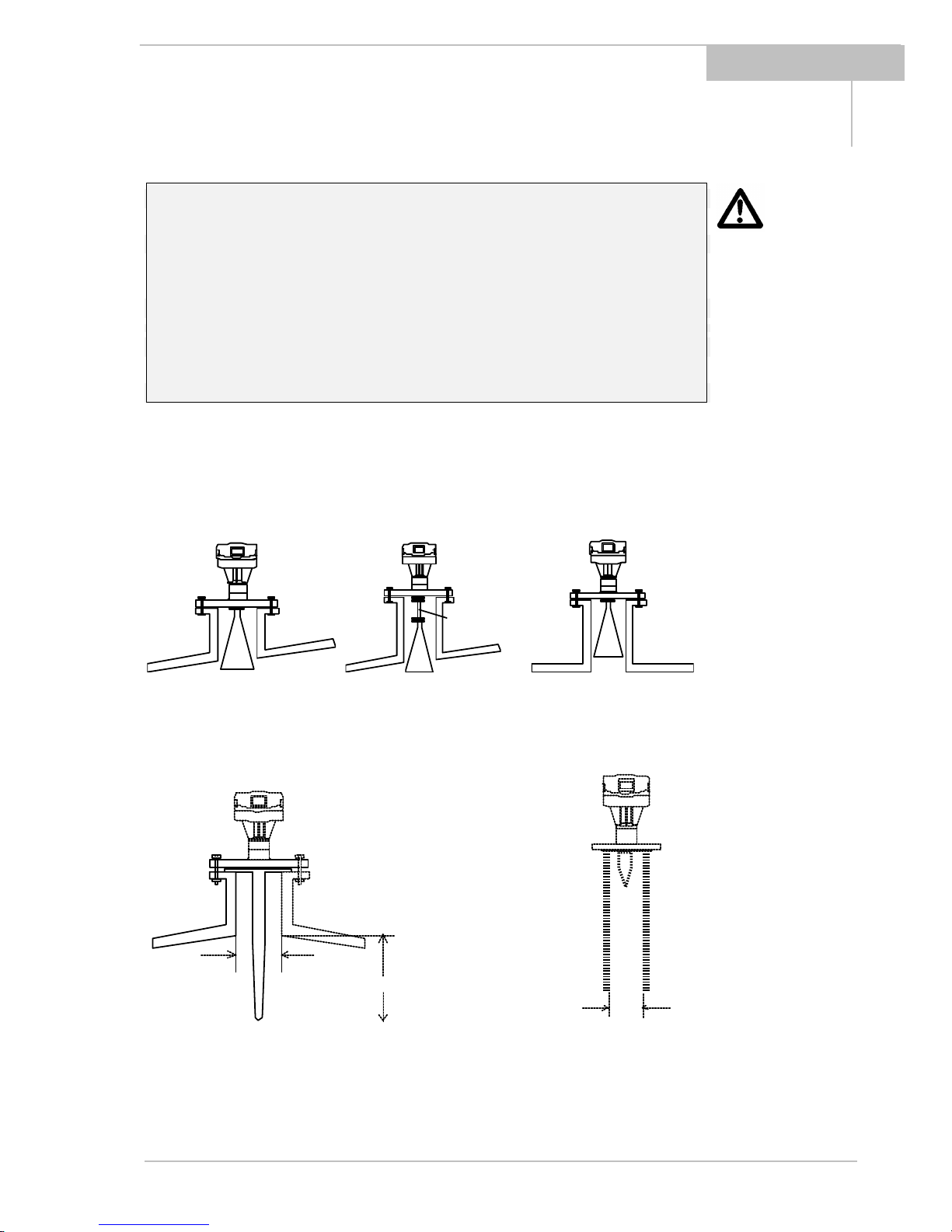
2.1 Field assembly..................................................................................................4
2.2 Mechanical installation.....................................................................................5
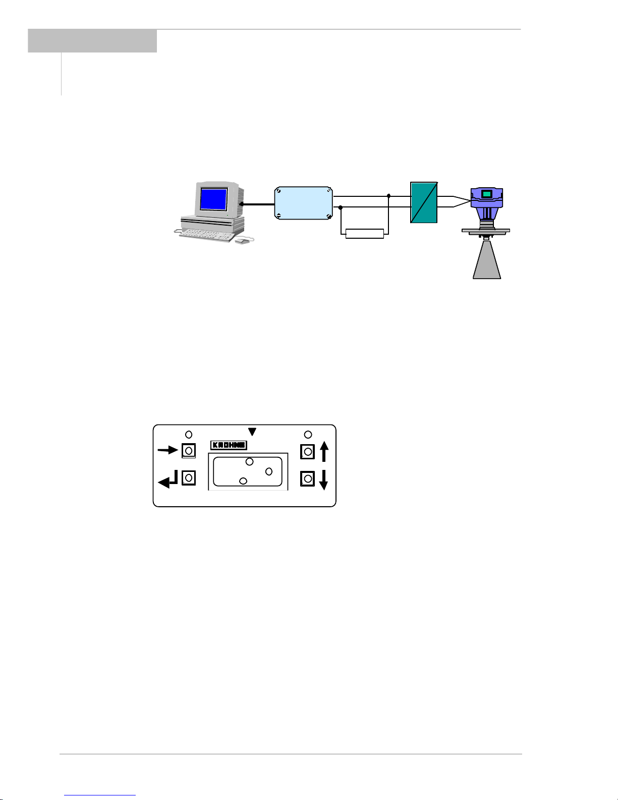
3Electrical connection...................................................................................7
4Setting the parameters...............................................................................8
5Maintenance, error handling....................................................................18
6Safety information.....................................................................................19
7Technical data (extract)............................................................................20
8BM 702 Level-Radar Type code...............................................................22
9Parameter check list.................................................................................24
Product liability and warranty:
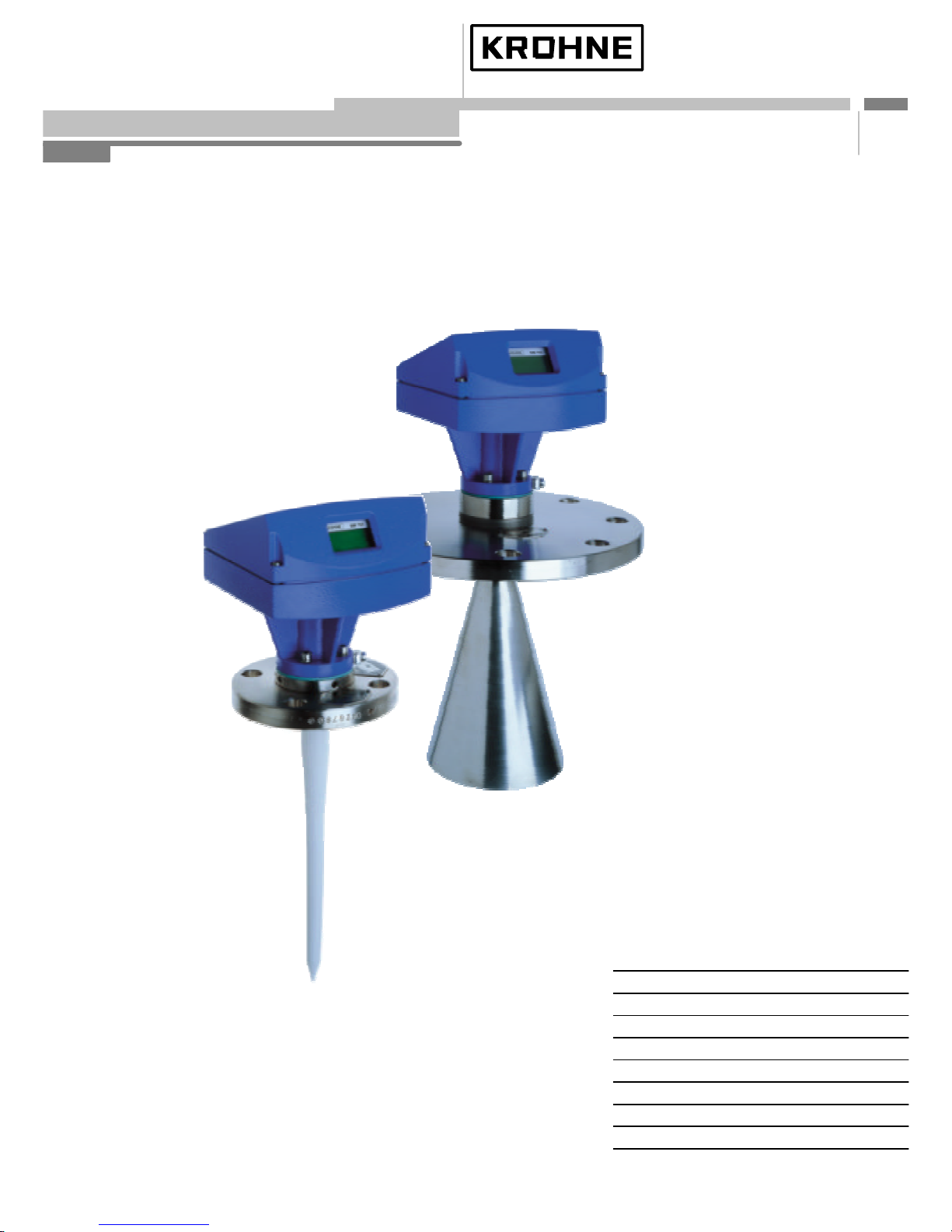
The BM 702 level gauge is designed solely for measuring the level, distance, volume and
reflection of liquids, pastes, slurries, particulate materials and solids.
The BM 702 level gauge does not form part of an overfill protection system as defined in
the WHG (= German water pollution regulation).
Local codes and regulations apply to its use in hazardous areas.
Responsibility as to suitability and intended use of these level gauges rests solely with the
user.
Improper installation and operation of our level gauges may lead to loss of warranty.
In addition, the "General conditions of sale", form the basis of the purchasing contract.
If you need to return the level gauge to the manufacturer or supplier, please refer to the
information given in Section 5
i
1Handling and storage
Safety advice
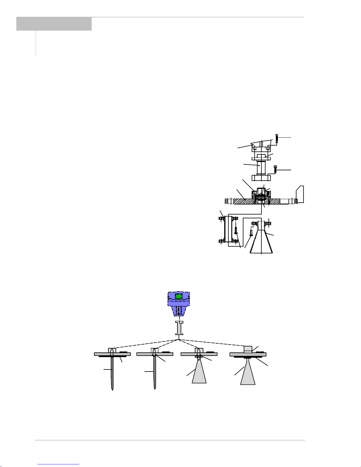
Depending on the version, the device will weigh between approx. 5 kg and 30 kg. To carry,
use both hands to lift the device carefully by the converter housing. If necessary, use lifting
gear.
When handling the BM 702, avoid hard blows, jolts, impact, etc.
When storing the "Wave-Stick" version, make sure that the device is not placed on its side
on the PTFE antenna, as this may cause the rod to bend.

4Installation and operating instructions BM 702 (07/00)
2Installation
Most of the BM 702 versions are supplied in fully assembled condition. In this case, you
may skip this chapter. However, if a device should be delivered in parts, or parts are
subsequently replaced, the following should be noted.
2.1 Field assembly
•For any necessary field assembly of the
BM 702, all parts are included with the
supply(studbolts,washers,etc.).
•Bolt the waveguide window (flange mount)
or distance piece, if supplied loose, to the
BM 702. Torque for the sets of 4 Allen
screws M(key size 5 mm): max. 8 Nm ∼
0.8 kpm (5.8 ft lbf).
•Note:Ensure the upper Teflon plug is kept
absolutely dry and clean! Moisture and dirt
will impair functionability of the BM 702!
•Bolt antenna extension to the antenna;
torque for the 3 stud bolts A: max. 8 Nm ∼
0,8 kpm (5.8 ft lbf).
Do not detach bolts H !
distance piece (for
high-temperature version
up to 250°C (482 °F)
upper Teflon plug
O-ring
lower Teflon plug
O-ring
BM70 A
connecting flange
antenna extension
antenna
M
HM
A
signal converter
Version:
Flange
Stick plating
(for Hastelloy,
Stick Gasket Gasket
Horn
antenna
Separation
(Metaglass)
Wave-Stick Wave-Stick
(PP or PTFE)
Flange system 96
with horn antenna
LP flange system
max. 2 bar
max. 2 bar
distance piece
(optional)
High temperature
plate Horn
antenna
Flange
Ti, Ta)
PTFE w/o plate with horn antenna
BM 702
converter

5Installation and operating instructions BM 702 (07/00)
2.2 Mechanical installation
Hazardous-duty systems:
•The BM 702 Ex is certified in conformity with European Standard
for use in Zone 0, 1
and2hazardouslocations(dependentonversion).
•Attention is drawn to the data and information given on the
nameplate of the
converter, the nameplate of the flange and the specifications in the
approval
certificates.
Safety:
•Check material compatibilityof antenna, extension, flange, gaskets, and PP or PTFE
(used in all versions) with the product! See also section 8 "Type code"!
Mounting on the tank nozzle
a) Devices with horn antenna:
The antenna should project out of the nozzle. If necessary, use an antenna extension.
Exception: in case of a symmetrical tank fitting.
Tank nozzle Tank nozzle Antenna
extension
Tank nozzle
b) Wave-Stick
Note the requirements imposed on nozzle diameter and nozzle length:
min. 50 mm
min. 200 mm
Tank nozzle
e.g. DN50
dia. 40...55 mm
Version for
still wells

6Installation and operating instructions BM 702 (07/00)
c) Purging device
Remove screw plug ¼" R and screw in
screwed tube joint, e.g. Ermeto ¼" R.
Consult “Ex“ specifications relating to the
purging circuit (provided by customer)!
Installation on the tank
•Do not forget the gasket when
positioning the BM
702 on the tank
nozzle flange. Align BM 702 and gasket,
slightly tighten nuts on stud bolts (by
hand).
•Press shielding strip C* in the gap
between tank and BM
702 flanges and
secure with strap retainer S* (both
items included with supply).
•Strap retainer S* must fit closely and
overlap both flanges.
* only required for European radio approvals
•Tighten down stud bolt nuts firmly. The
tightening torque is dependent upon
the strength properties of the stud
bolts and the pressure rating of the
tank C* = shielding strip B = BM 702flange
S* = strap retainer F = tank flange
Positioningonthe tank
D
>1/7×H, but max. 1/3×D H
Recommended distance Do not position in Do not position
from the tank wall tank centerline!above internals!
(multiple reflections!) (interference reflections!)
A Stilling wellor Wave-Guide may be mounted in any position on the tank!

7Installation and operating instructions BM 702 (07/00)
When using the PTFE Wave-Stick in hazardous areas of Zone 0, any electrostatic charging of
the stick, e.g. by flow of product, must be avoided!
3Electrical connection
To open the signal converter, please use a screwdriver and release the four visible screws
on top of the blue housing.
Terminal assignment
BM 702:
The polarity of the 4-20 mA connection
is arbitrary. FE 1
2
4-20mA
current-
loop
cable gland
Equipotential bonding
When used in hazardous areas, the BM 702 Ex can be incorporated in the PA
equipotential bonding system, e.g. by using the separate U-clamp terminal at the “neck“
of the BM 702 Ex.
Rated temperature of connecting cables: see Section 6.
Supply voltage at the terminals (1,2)
The 4-20 mA supply must be able to provide the following voltage U at the terminals of the
BM 702 – dependent on the current I. Please consider also the line resistance and possible
loads on the secondary side of the supply unit.
4mA
12mA
8mA
16mA
20mA
3.6mA 22mA I
U
13V
14V
15V
16V
17V
The allowed upper limit R for load+line resistance is depending on the specification of the
supplyunit:
U @20mA (supply unit) 14 V 15 V 16 V 17 V 18 V
Max. resistance R 50 Ω100 Ω150 Ω200 Ω250 Ω

8Installation and operating instructions BM 702 (07/00)
BM702
9.500
Füll. m
m_____
4 4
32
1
4Setting the parameters
Setting parameters via program PC-CAT
With the program PC-CAT, version 3.01 or higher, you can configurate BM 702 instruments
in a very comfortable way from a PC. Connect the non-intrinsically safe side of the isolation
amplifier over a load between 120 Ωand 350 Ωto the Smart adapter (delivered together
with PC-CAT) and connect it with a serial port of the PC.
The used isolation amplifier must be HART® compatible.
Local display (optional)
(1) Numeric display, measured values
(2) Alphanumeric display, function/unit
(3) 6 Markers to display measurement
status
(4) 4 keys for configuration and error
interrogation
Adapter
≥ 120 Ω
RS232
isolation
amplifier

9Installation and operating instructions BM 702 (07/00)
Function of keys (only together with local display)
Operator control can be carried out with the aid of local display unit after opening the
housing. However, a particularly convenient form of parameter setting is offered by the PC
program PC-CAT (special accessories, see above).
→ (cursor key) - selects the configuration menu,
- branches the menu to the next lower level,
- shifts the cursor* to the next column on the right.
↑ resp. ↓ (select key) - branches the menu to the next digit on the same
level,
- changes the content (digit, text character) at the
cursor* position.
↵ (ENTER key) - branches the menu to the next higher level,
- stores newly entered parameters,
- executes displayed functions,
- selects special functions (e.g. error memory,
see Sect. 5).
* The cursor position is signalled by flashing of the character at the appropriate place.
Meaning of status markers (only for version with local display)
The 6 markers ?x below the local display only show information about the status of
measurement and are no error displays!
?1: No current measured value: The device is searching for a new value. If the
search for a plausible level fails for a certain time, "SIGNAL DOWN" appears as
error display.
?2: Signal too strong: Mean of reflected microwaves is very high. Gain is automa-
tically stepped down.
?3: Poor spectrum: Brief showing of this marker has no significance. If permanently
on, this may result in uncertain (incorrect) measured values or the error message
"NO M.VALUE".
?4: No measured value as yet:Evaluable measured values not available after the
device has been started up. Measured value automatically set to the level of the
tank bottom. This marker disappears when the first valid measured value is
obtained.
?5: Tankbottom: In tanks with dished bottom, for example, the measuring signal can
"disappear" if measurements are carried out near the bottom. The measured value
is then automatically set to the level of the tank bottom.
?6: Measurement frozen: Device is in the block distance detection (see below).

10 Installation and operating instructions BM 702 (07/00)
Simply scaling the current output
1) Drain the tank completely to the 0% marking (= 4 mA) 1).
2) Press the lower keys (↵und ↓) down, until the
asterisks on the display „TANKHEIGHT|********“ are
replaced by the actual measured distance value 2).
3) Then release and press ↵. In the lower line: „SURE
NO?“ is displayed.
4) If this value is not plausible or the tank is not empty,
abort by↵. Or accept the value by pressing ↑(“SURE
YES?”) and then ↵.
5) Now the tank height is set.
6) In the next step you can also enter this value as 4 mA
scaling (0%). Press ↵. In the lower line now: „SURE NO?“
is displayed again.
7) If this value shall not be stored, abort by↵. Or accept
this 4mA scaling by pressing ↑(“SURE YES?”) and then ↵.
8) Fill the tank to the 100% mark. Use the same procedure
for the 100% point = 20 mA only now by pressing the top
keys →and ↑ 1) 2).
9) First the measured distance can be taken as block
distance. After this you can enter or adjust the 20 mA point
(100%) according to the actual level.
1) This example was written for the case: current output = level (default). For distance measurement the
points 0% (short distance = high level) and 100% (large distance = low level) are exchanged
2) If no reliable measurement is possible „NO ACCESS“ is displayed. Abort by pressing ↵
0%
TANKHEIGHT
1234 mm
↵
TANKHEIGHT
1234 mm
SURE YES? 1.
2.
100%
BLOCKDIST.
567 mm
↵
TANKHEIGHT
1234 mm
SURE NO?
SCALE 4mA
0 mm
SURE NO?
SCALE 4MA
0 mm
SURE YES? 1.
2.
SCALE 4mA
0 mm
↵

11 Installation and operating instructions BM 702 (07/00)
Description of functions
The table on the following 3 pages provides an overview of all parameters that can be set in
the configuration menu.
This is followed by more precise explanations of some functions and a typical configuration.
Configuration menu (version 7.00)
Function (Fct.) Input range Description
1.0 OPERATION
1.1 DISPLAY
1.1.1 FCT.DISP identical with 3.2.1
1.1.2 UNIT.LENGTH identical with 3.2.2
1.1.3 UNIT.CONV. identical with 3.2.3
2.0 TEST
2.1 HARDWARE
2.1.1 MASTER Master hardware test.
2.1.2 DISPLAY Display hardware test.
2.1.3 STATUS Status information for Service
2.2 CUR.OUTP.I
2.2.1 VALUE I Value display Display of actual value of the
current output.
2.2.2 TEST I Select 3.6 mA/4 mA/6 mA/...
... 20 mA/22 mA Output of selected value to
the current output. With
safety query.
2.4 FIRMWARE
2.4.1 MASTER Display Display of master firmware
version.
3.0 INSTALL.
3.1 BASIS.PARAM
3.1.1 TANKHEIGHT Select unit m/cm/mm/
inch/Ft
Enter 0.50 ... 20.00 [m]
Enter tank height (see
explanatory notes).
The unit entered here is also
used for all other length
entries.
3.1.2 BLOCKDIST Enter 0.10 [m] ... tank height Enter block distance = non-
measurable range below
bottom edge of flange (see
explanatory notes).
3.1.3 ANTENNA Select STANDARD
WAVE-STICK Select antenna type. WAVE-
STICK for all Wave-Stick
versions, except type "SW"
for stillwells.
All other = STANDARD.
3.1.4 ANT.EXTENS. Enter 0.00 [m] ... tank height Enter length of antenna
extension (not for Wave-
Stick: set to= 0)
3.1.5 DIST.PIECE Enter 0 ... 2000 [mm] Enter length of distance
piece above flange (high
temp. version = 120 mm).
3.1.6 STILLWELL Select NO / YES
If “YES“: enter 25 ... 200 [mm] Selection: without or with
still well.
With still well: enter inside
diameter in [mm]

12 Installation and operating instructions BM 702 (07/00)
Function (Fct.) Input range Description
(compensates different
wave speeds in still wells)
3.1.7 REF.OFFSET Enter -10.00...0...+10.00 [m] Reference offset is added
to measured distance
values.
3.1.8 TB.OFFSET Enter-100.00...0...+100.00 [m] Tank bottom offset is added
to measured level values.
3.2 DISPLAY
3.2.1 FCT.DISP Select LEVEL
DISTANCE
CONVERSION
Select function of display
(value to be displayed).
See also explanatory notes.
3.2.2 UNIT.LENGTH Select m/cm/mm/
inch/Ft/
PERCENT/BARGRAPH
Select unit for length value
to be displayed (only for
level and distance).
3.2.3 UNIT.CONV. Select m3/l(Liter)/US Gal/
GB Gal/Ft3/bbl/PERCENT/
BARGRAPH/USER UNIT
Select unit for conversion
value to be displayed
(“volume table“).
(see explanatory notes)
3.2.4 USER UNIT Text entry 10 characters Enter user-defined unit for
the conversion table.
3.2.5 ERROR MSG. Select NO/YES Select whether error
messages to be shown in
display.
3.3 SIGNAL OUT
3.3.1 FUNCTIONI Select OFF/LEVEL/DISTANCE/
CONVERSION/SW.OUTP. Select function of the
current output.
3.3.2 RANGE I Select 4-20mA
4-20mA/E3.6
4-20mA/E22
Select range/error status
for the current output (hold
last value or 3.6 mA/22mA
in error status)
3.3.3 SCALE 4mA Enter -200.00 ... +200.00 [m]
0.00 ... 99999.99 [m3]Enter lower measuring
range value for the current
output (4 mA).
(see explanatory notes)
3.3.4 SCALE 20mA Enter -200.00 ... +200.00 [m]
0.00 ... 99999.99 [m3]Enter full-scale range value
for the current output (20
mA).
(see explanatory notes)
3.3.5 BAUDRATE Select 1200 Bd Baud rate for HART®
communication(donot
change!).
3.3.6 ADDRESS Enter 0... 255 Enter device address.
(for HART® multidrop)
3.3.7 PROTOCOL Select HART/KROHNE-PC Select communications
protocol
3.4 USER DATA
3.4.1 LANGUAGE Select GB-USA/D/F/I/E/P/S Select language for the
optional display.
3.4.2 ENTRY CODE 1 Select NO/YES Switch the access lockout
on/off.

13 Installation and operating instructions BM 702 (07/00)
Function (Fct.) Input range Description
If YES, for every access a 9-
digit entry code on the 4
keys is necessary.
3.4.3 CODE 1 Enter code (RRREEEUUU)Enter the entry code for
access lockout.
3.4.4 LOCATION Enter text (8 characters) Enter a device identifier.
3.5 APPLICAT.
3.5.1 AUTO TANKH. Special function Automatic determination of
tank height
(see explanatory notes).
3.5.2 EMPTY.SPEC. Select OFF/ON/
RECORD Recording the profile of the
empty tank (empty-tank
spectrum) (see explanatory
notes).
3.5.3 TIMECONST. Value 1...10...100 [s] Enter time constant for
measured-value filtering
3.5.4 TRACING.VEL. Value
0.01...0.50...10.00 [m/Min] Enter the maximum rate of
change in level that can
occurinoperation.
3.5.5 MULT.REFL. Select NO/YES Switch the multi-reflection
identifier on/off.
3.5.6 BD-DETECT. Select NO/YES Switch the block distance
(overfill) identifier on/off
(see explanatory notes).
3.5.7 FUNCT. FTB Select OFF/
PARTIAL Select function of tank
bottom tracing system (see
explanatory notes).
3.5.8 EPSILON R Enter 1.1000 ... 8.0000 Enter relative permittivity of
product (only for Fct. 3.5.7)
3.5.9 TANKTYPE Select STORAGE T./
PROC TANK Select tank type.
STORAGE T. = smooth
product surface
PROC TANK = slightly
disturbed product surface
The default settings are marked in the table bold.

14 Installation and operating instructions BM 702 (07/00)
Explanatory notes
Tankheight
The tank height (Fct. 3.1.1) for the BM 702 is defined as the distance between the top
edge of the tank connecting flange and the bottom reference point. The bottom reference
point is that “point“ in the tank on which the microwaves of the BM 702 hit and from which
they are reflected. This may be the tank bottom (symmetrical tank with flat bottom) or the
non-horizontal part of the bottom (e.g. tank with dished bottom) or an additionally fitted
plate. The BM 702 cannot measure below this point (“sump“ in the tank).
Note: When the tank is completely empty and the tank bottom provides good reflections
(flat, not dished bottom!), the tank height can also be automatically determined with the
aid of Function Fct. 3.5.1 AUTO TANKH. Before confirming, check carefully that the
proposed tank height is plausible!
Block distance
The “block distance“ function (Fct. 3.1.2) defines a zone below the top reference point in
which measurements are not meant to take place. The value should be at least 10 - 20 cm
greater than the length of antenna+antenna extension, or at least 20 cm in the case of the
Wave-Stick.
Signals within the block distance are suppressed; a rise in the tank filling above this limit
(response threshold) will lead to a measuring result corresponding to a distance = block
distance, when Fct. 3.5.6 BD-DETECT. is switched on.
Scaling of the current output
The scaling of the current output (Fct. 3.3.3: level 1 = 4 mA ; Fct. 3.3.4: level 2 = 20 mA)
should if possible lie within the measuring range (between bottom reference point and
response threshold).
By pressing the two upper keys (→and ↑) or the two lower keys (↵and ↓) at the same
time, the 0% setting (= 4 mA) or 100% setting (= 20 mA) can be programmed according to
the actual level (see page 9).

15 Installation and operating instructions BM 702 (07/00)
+
+
+
+
+
+
+
+
+
+
+
+
+
+
+
+
+
+
+
+
+
+
+
+
+
+
+
+
+
+
+
+Sump
non
measurable
zone
tank height
(Fct. 3.1.1)
Fct. 3.1.4
upper reference point
(top edge of tank connecting flange)
block distance (Fct. 3.1.2)
response
current output
20
mA max
(Fct. 3.3.4)
4min
(Fct. 3.3.3)
lower reference point
(tank bottom / datum point)
Fct. 3.1.5
threshold
measuring
mA
[e.g.: 5.30 m]
[e.g.: 0]
[e.g.: 0]
[e.g.: 0.6 m]
[e.g.: 0.4 m]
[e.g.: 4.0 m]
range
Empty-tank spectrum
To enable the BM 702 to identify and blank out interference signals, e.g. caused by fixed
and moving tank internals, the tank profile (empty-tank spectrum) needs to be recorded
once only prior to (initial) start-up. For recording, the tank should be completely empty and
all moving parts (e.g. agitators) switched on. If major interference through internals is not
expected, recording of the empty-tank spectrum can also be dispensed with, since the
factory has already carried out and stored a partial empty spectrum of the flange system.
Empty-tankspectrumrecordingviadisplay
After selecting menu item Fct. 3.5.2, press key →. The display then shows whether the
empty spectrum is currently ON or OFF. Then press the ↵key if no change is to be made, or
use the ↑key to choose between the following options:
•ON: the empty-tank spectrum is (again) switched on and taken into account for
measurements.
•OFF: the empty-tank spectrum is not taken into account for measurements, but
remains stored in the BM 702 and can be switched on again at a later date.
•RECORD: the existing empty-tank spectrum is to be deleted and a new one
recorded.

16 Installation and operating instructions BM 702 (07/00)
After selecting "RECORD": if other parameters had previously been changed, the query
"ACCEPT YES" is first made as to whether they are to be stored. In this case, confirm by
pressing ↵. To record, use the ↑key to select one of the following options:
•MAX. VALUES: (only maximum values are taken into account when the empty-tank
spectrum is recorded; useful e.g. with “difficult“ agitators).
•AVERAGE: (values are averaged; this setting can be used for most applications).
After selecting with the ↑key, press the ↵key to select TOTAL or the ↑key to select
PARTIAL.
•When TOTAL is selected, the empty-tank spectrum is recorded over the entire range
(tankheight).
•If the tank has not been fully drained, the empty-tank spectrum can also be
recorded up to a certain distance, in which case the menu item PARTIAL should be
selected. When this has been selected, a query takes place by way of the ↵key
concerning the distance value up to which the empty-tank spectrum is to be
recorded. The tank area below the current filling level is then excluded from the
empty-tank recording. It is recommended to maintain a safety distance of 20 to 30
cm from the actual product distance.
Subsequently press key ↵to start recording the empty-tank spectrum. The display starts
with “200“ and counts down to “0“. The sign WAIT... is shown in the display. READY
appears after approx. 1-3 minutes. Then press key ↵five times to store the recorded
empty-tank spectrum, which is taken into account for measurements.
Empty-tankspectrumrecordingviaPC-CAT
Connect the BM 702 and press in the display mode of PC-CAT the key combination Ctrl-L.
The type of empty-tank spectrum can be selected by one of the following keys:
1: Max.Values 4: Max. Partial A: Break
2: Average 5: Avg. Partial
Tank bottom tracing mode (FTB)
The BM 702 includes an additional function for measuring reliably low levels in tanks with
flat bottom and poorly reflecting products (low dielectric constant). This tank bottom tracing
system (abbreviated FTB) is activated in the vicinity of the tank bottom (max. 20% level).
Given higher levels, the normal measuring method is used (reflection from the product
surface).
If the measurement jumps to the correct level only after filling above a certain level (approx.
0.3-1.0 m), you can activate the FTB function Fct. 3.5.7 „PARTIAL“. The relative permittivity
εrof the tank product must be set in Fct. 3.5.8. If it is not known, enter the figure of 2.0.
Since the exact position of the tank bottom must be known for this process, it is advisable
when using the FTB to determine the tank height automatically with an empty tank, using
Fct. 3.5.1.
Conversion table/Volume table
A table consisting of a maximum of 50 points can be stored in the BM 702 for non-linear or
linear conversion of the level, e.g. into a volumetric value. This table, however, can only be
programmed with the PC-CAT program (Fct. 3.7.2).

17 Installation and operating instructions BM 702 (07/00)
Sequence for setting parameters (example) (for version with local display)
The following description refers to a storage tank with the parameter examples taken from
the illustration in this Section. If the device no longer contains the default parameters, the
keystroke combination for entering the numerical values may differ.
Activity Keys to be
actuated
Content of BM 702
display after activity
Entry into configuration menu →Fct. 1.0
OPERATION
Setting the parameter: tank height ↑↑→ → Fct. 3.1.1
TANKHEIGHT
Display of default value →10.000 m
Input of tank height "5.30 m" →↓ → 5x↑→
3x
↑
05.300 m
Confirm tank height and move to block
distance
↵↑Fct. 3.1.2
BLOCKDIST
Display default value →0.5000 m
Enter block distance "0.60 m" → ↑ 0.6000 m
Confirm block distance and move to current
output configuration
↵ ↵ ↑ ↑ Fct. 3.3
SIGNAL OUT
Move to lower range value → ↑ ↑ Fct. 3.3.3
SCALE 4 mA
Display default value →+ 00.000 m
Enter lower range value (0.4 m = 4 mA) 3x →4x↑+ 00.400 m
Confirm lower range value and move to full-
scale range value
↵ ↑ Fct. 3.3.4
SCALE 20mA
Display of default value →010.00 m
Enter full-scale value (4.0 m = 20 mA) 2x→↓→4x↑004.00 m
Confirm full-scale value and move to empty
tank spectrum
↵↵↑ ↑ → ↑ Fct. 3.5.2
EMPTY.SPEC.
Select: re-record empty spectrum → ↑ ↑ RECORD
Storechangedparameters ↵ACCEPT. YES
Confirm and select: averaging ↵ ↑AVERAGE
Confirm and start recording; then wait for
approx. 1-3 minutes!
↵ ↵ READY
Confirm and move to tank type ↵7x↑Fct. 3.5.9
TANK TYPE
Display of default value →PROC TANK
Select tank type "storage tank" ↑ ↑ STORAGE T.
Return to measurement function with
confirmation of changed parameters 5x↵PARAM.CHECK,
then START,
then meas.val. display

18 Installation and operating instructions BM 702 (07/00)
5Maintenance, error handling
Replacement of the signal converter
Before commencing, note the parameters of the BM 702 and switch off the power supply!
1. Disconnect all cables from the terminals in the terminal compartment.
2. Remove the 4 Allen screws M (Allen key size 5 mm) and lift off the signal converter.
The flange unit (incl. waveguide window) will remain tight even with pressurized tanks.
Caution
On pressurized tanks, do not on any account remove the 4 screws H connecting the
waveguide window to the BM 702 flange! DANGER!
3. Fit the new BM 702 converter.
4. Reconnect all cables in the terminal
compartment, as described in Section
3.
5. Check against the enclosed report on
settings whether the factory-set
parameters are correct for your
application. If not, reset.
6. Record the empty spectrum,
see Section 4.
Important: Make sure that the screw thread
of the covers on the terminal and electronic
compartments is well greased at all times.
distance piece
(for hightemperature
version up to 250°C (482°F)
O-ring
BM70
connecting flange
signal converter
M
H
Returning a BM 702
The party returning a device is obligated to check and ensure that all cavities in the device
are free from dangerous substances (toxic, caustic, flammable, water-endangering),and
that a certificate is enclosed with the device confirming that it is safe to handle.
Error display during measurement (onlyforversionswithlocaldisplay)
When function 3.2.5 "ERROR. MSG." is set to YES, any error occurring during measurement
is indicated in the display and alternates with the measured value for as long as the error is
present.
In addition, all errors are stored. Press the keystroke combination ↵↑→→to get into
the error list. You can page through the list with key→, and acknowledge the errors at the
end - if required - by "QUIT YES". Press key↵twice to return to the measuring mode.
Fatal errors (FATAL ERROR), that are detected when the device is started up, render
operation of the BM 702 impossible.

19 Installation and operating instructions BM 702 (07/00)
6Safety information
iHazardous-duty systems
•Types of protection in the BM 702 terminal compartment:
Intrinsically safe"ia"
•Consult the relevant wiring and installation regulations, e.g. VDE 0165, before
mounting, dismantling or making electrical connections in a hazardous area
Temperature rating of connecting cables:
The temperature rating of connecting cables is dependent on the maximum temperature of
the flange:
Version Max. flange
temperature Cable temperature
rating
Without high temperature ≤100°C (212°F) 70°C (158°F)
distance piece > 100°C (212°F) 80°C (176°F)
With high temperature ≤200°C (212°F) 70°C (158°F)
i
distance piece > 200°C (212°F) 80°C (176°F)

20 Installation and operating instructions BM 702 (07/00)
7Technical data (extract)
Tank height (measuring range) 0.5 to 20 m / 1.6 to 65.6 ft
Measuringaccuracy (distance) from 1m/3ft: +1cm/0.4” ; from 5m/16ft: +0.2%
Measured-value resolution 1 mm / 0.04”
Rate of change in level max. 10 m/min / 32.8 ft/min (tracking speed)
Connecting flanges
Hornantenna/Wave-Guide DIN 2501 DN 50 to DN 200 / PN 6 to PN 64 and
higher;
Shape C to DIN 2526 or others
ANSI B16.5 2” to 8",
Class 150 lb or 300 lb, RF
Wave-Stick DN 50...150 or ANSI 2”...6”, dairy DIN 11851
DN 50/65/80, Tri-Clamp 2/3/4”,
SMS 51/63/76 mm, G 1½"
Max. allowable operating pressure -1 bar (vacuum) to max. 64 bar / 928 psig,
depending on version and flange pressure rating.
(see name plate)
LP flange system with horn antenna, Wave-Guide or Wave-Stick without flange plate
-1 bar (vacuum) to +2 bar /29 psig
V96 flange system with horn antenna or Wave-Guide:
Connection:
nominal dia. Flange rated pressure
PN 16 PN 25 PN 40 PN 64
DN inches bar psig bar psig bar psig bar psig
80 3 16 232 --- --- 40 580 64 928
100 4 16 232 --- --- 38 551 55 797
150 6 16 232 --- --- 34 493 47 681
200 8 16 232 25 362 32 464 45 652
Wave-Stick: max. 16 bar / 232 psig, temperature-dependent:
-20 +150+100
-1
+1
+16 46 - 0.3·T[°C] bar
temperature T
pressure
+232
[psig] [bar]
+14
-14
+212
+302°F
745 - 2.42·T[°F] psig
Table of contents
Other KROHNE Radar manuals
Popular Radar manuals by other brands

Endress+Hauser
Endress+Hauser Levelflex FMP55 Brief operating instructions

Endress+Hauser
Endress+Hauser Levelflex M FMP45 operating instructions

Furuno
Furuno WR110 installation manual

Bindicator
Bindicator F78MP Series Installation & operation manual

Traffic Logix
Traffic Logix SafePace 100 Series installation manual

Honeywell
Honeywell BENDIX/KING RDR 2000 installation manual