8.2.1 Edition 08.10
DK S N P GR
➔ www.docuthek.com
D GB F NL I E
TR CZ PL RUS H
© 2008 – 2009 Elster GmbH
Please read and keep in a safe place
Please read through these instructions
carefully before installing or operating. Follow-
ing the installation, pass the instructions on to the
operator. These instructions can also be found at
www.docuthek.com.
Explanation of symbols
• , 1 , 2 , ... = Action
= Instruction
Liability
We will not be held liable for damages resulting
from non-observance of the instructions and non-
compliant use.
Safety instructions
Information that is relevant for safety is indicated in
the instructions as follows:
DANGER
Indicates potentially fatal situations.
WARNING
Indicates possible danger to life and limb.
CAUTION
Indicates possible material damage.
All interventions may only be carried out by qualified
gas technicians. Electrical interventions may only be
carried out by qualified electricians.
Conversion, spare parts
All technical changes are prohibited. Only use OEM
spare parts.
Transport
On receipt of the product, check that the delivery is
complete (see Part designations). Report any trans-
port damage immediately.
Storage
Store the product in a dry place. Ambient tempera-
ture: see Technical data.
Operating instructions
Translation from the German
GB
GB-1
Safety
Contents
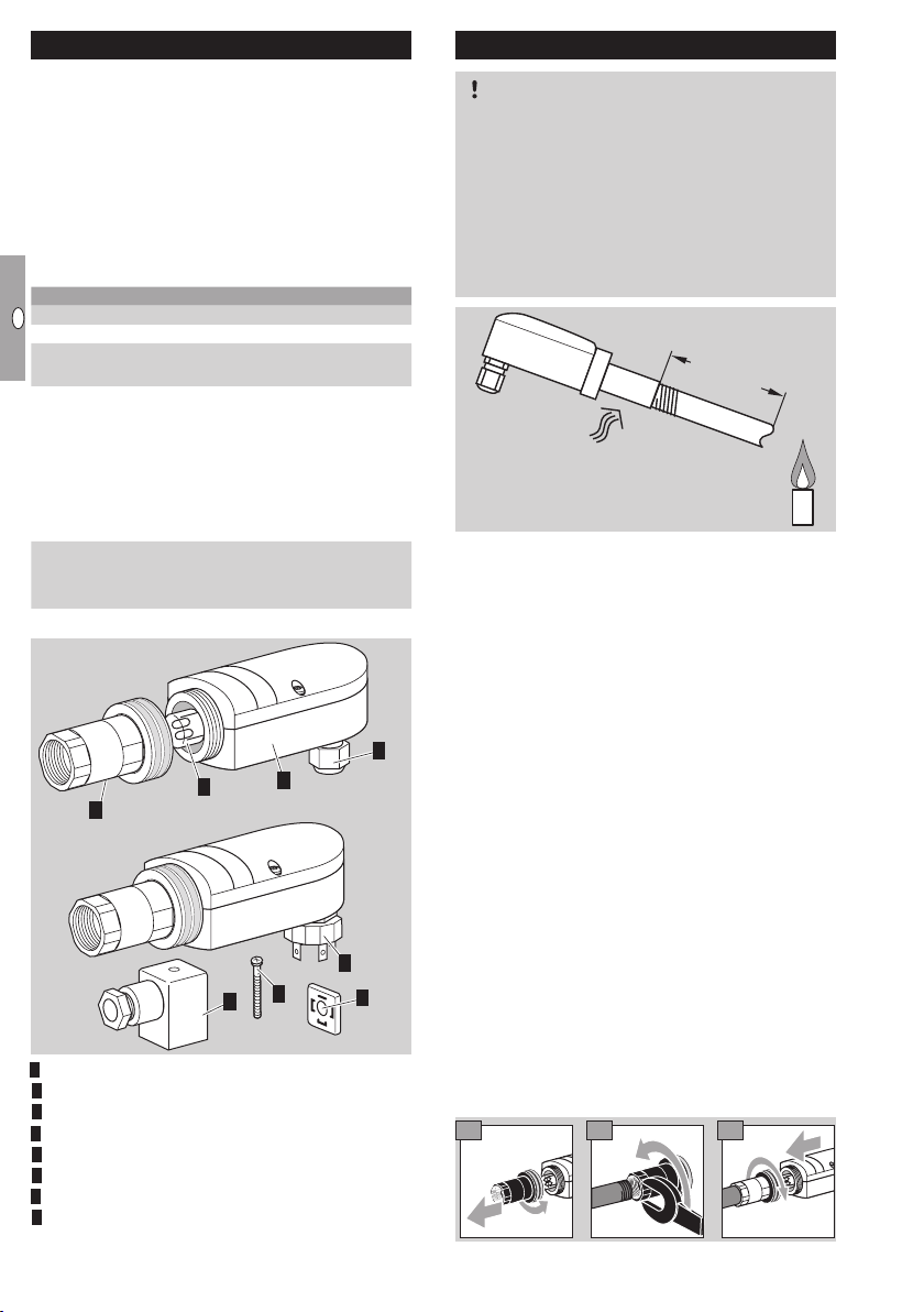
UV sensor UVS 10
UV sensor UVS 10 ......................1
Contents ..............................1
Safety.................................1
Checking the usage . . . . . . . . . . . . . . . . . . . . . 2
Type code..............................2
Installation ............................2
UVS 10 with internal thread adapter. . . . . . . . . . 2
UVS 10 with UVS 1 adapter. . . . . . . . . . . . . . . . 3
Cable selection.........................
Cable installation .......................
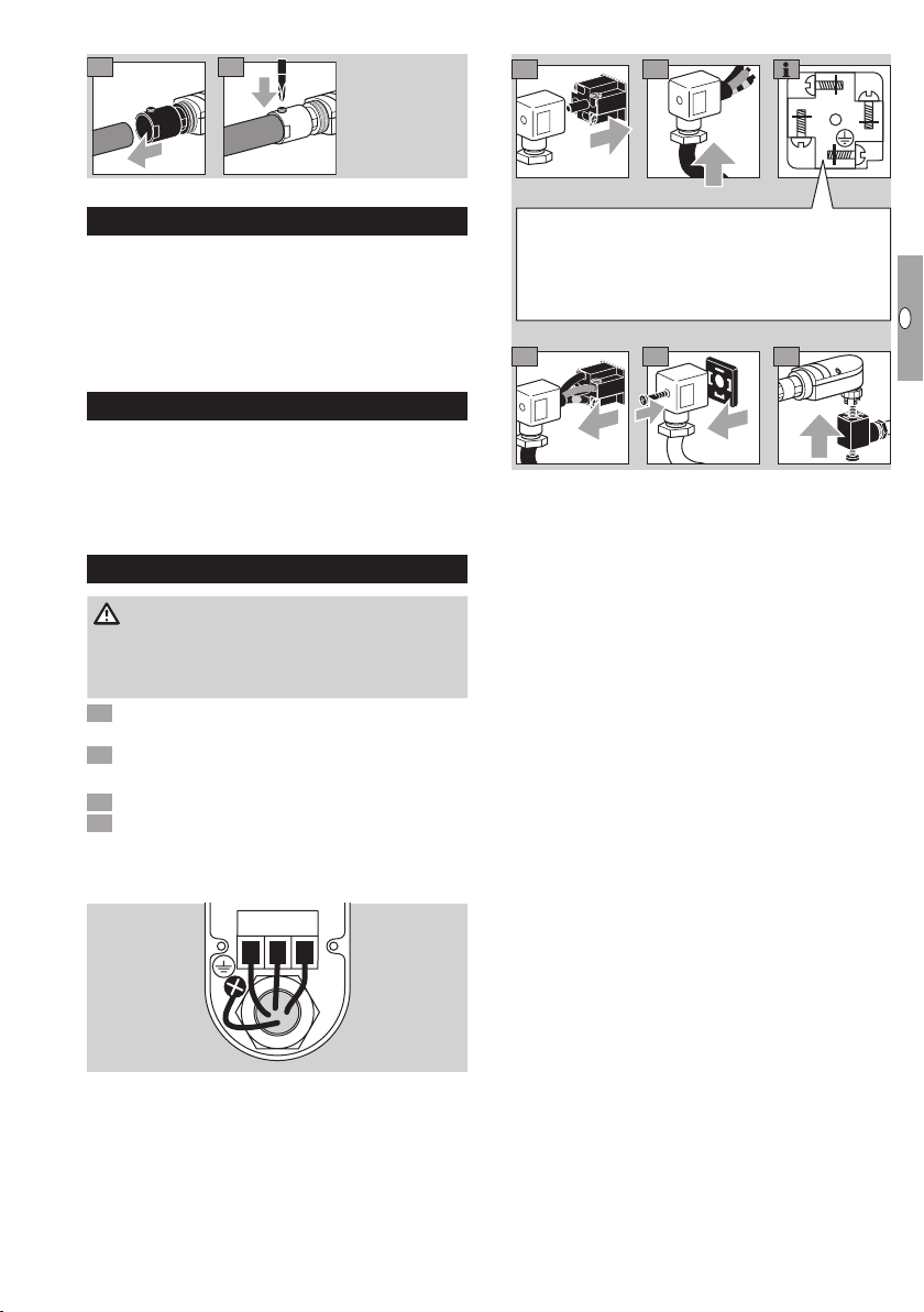
Wiring ................................
UVS 10..G1............................3
UVS 10..P2 ............................3
Maintenance...........................4
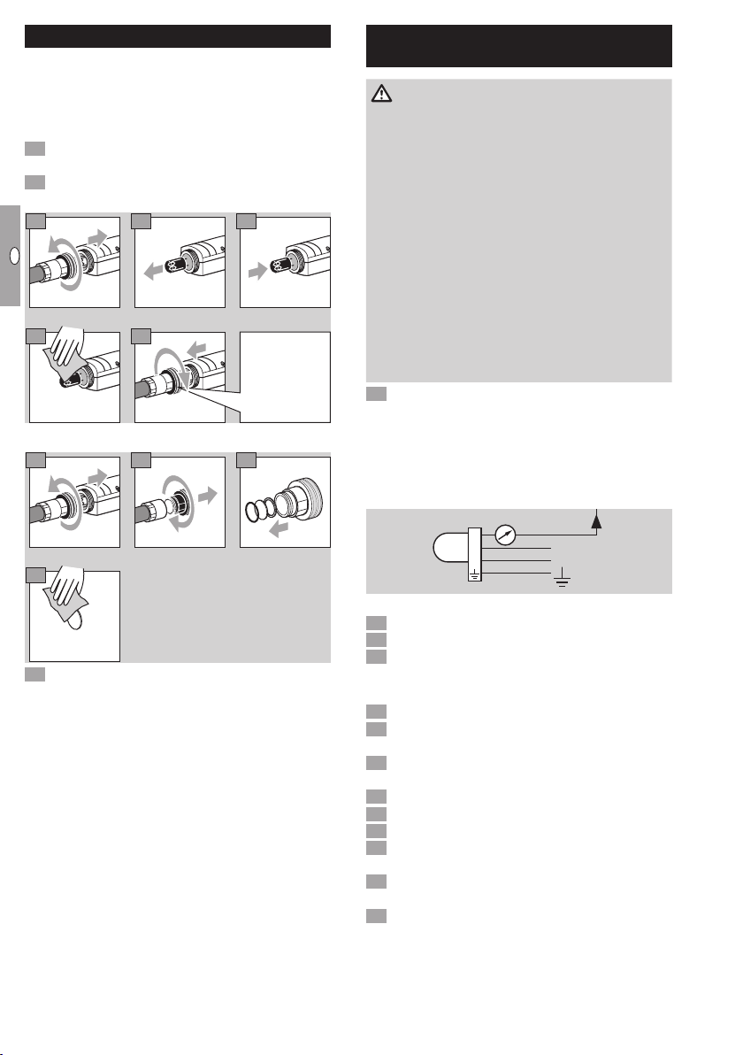
Replacing the UV tube . . . . . . . . . . . . . . . . . . . . 4
Cleaning or replacing the quartz glass disc . . . . 4
Assistance in the event of malfunction . . . . . 4
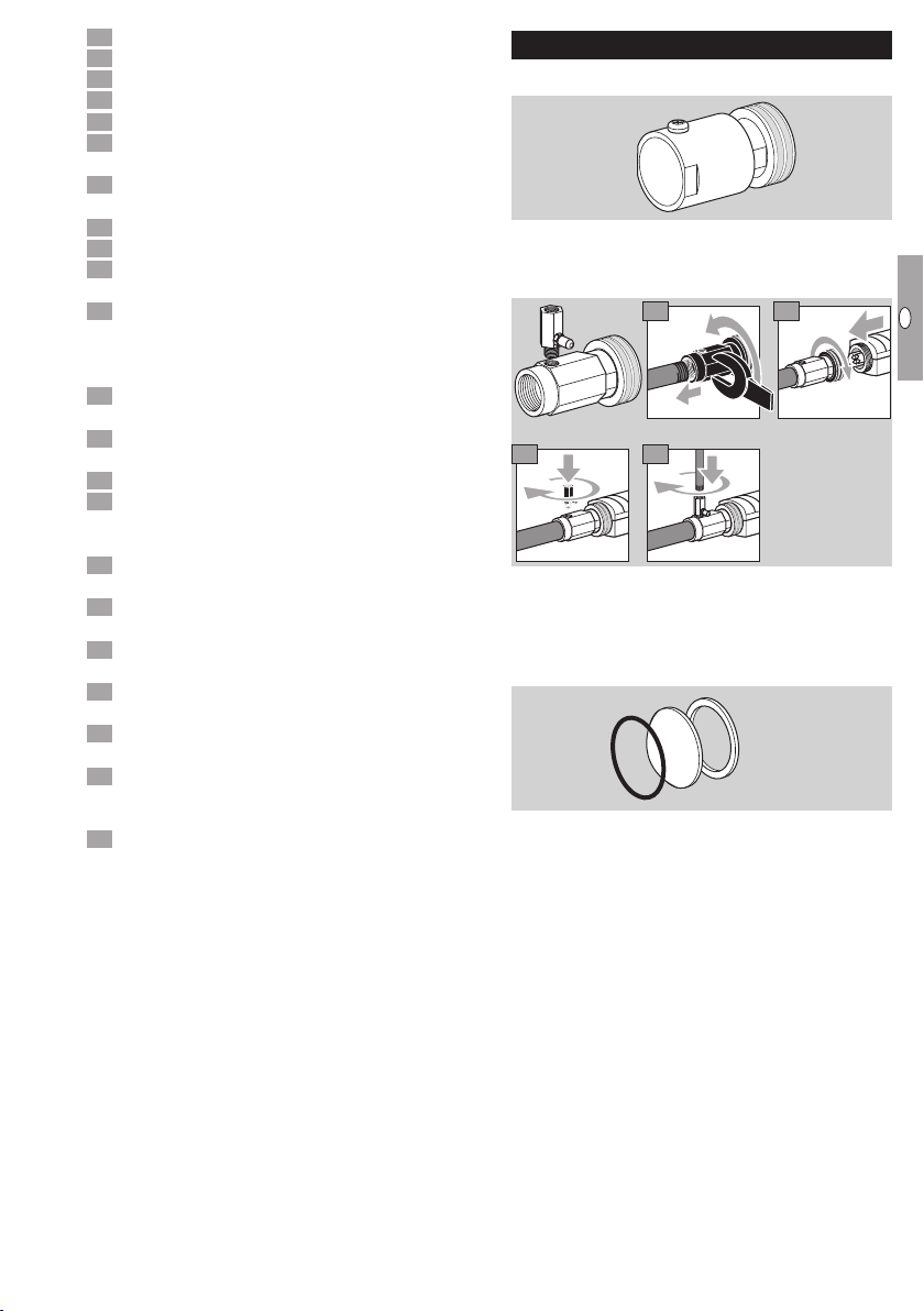
Accessories ...........................5
Adapter UVS 1 with quartz glass disc . . . . . . . . 5
Cooling air adapter with quartz glass disc . . . . . 5
Quartz glass lens with seals . . . . . . . . . . . . . . . . 5
Technical data..........................6
Contact ...............................6