GB-3
GB
Maintenance
CAUTION
In order to ensure smooth operation: clean or re-
place the filter pad of the GFK every year, or every
six months if operated with biologically produced
methane.
▷
The filter pad must be changed at a pressure
gradient ≥20mbar (8"WC).
▷Pressure test points on the cover:
GFK 15 to 100:
Inlet side: Rp 1/8 pressure test nipple,
Outlet side: Rp 1/8 pressure test nipple.
GFK 125 to 250:
Inlet side: Rp 1/8 plug,
Outlet side: Rp 1/8 plug.
GFK 15T to 100T:
Inlet side: Rp 1/8 plug,
Outlet side: Rp 1/8 plug.
∆pmax. = 20 mbar
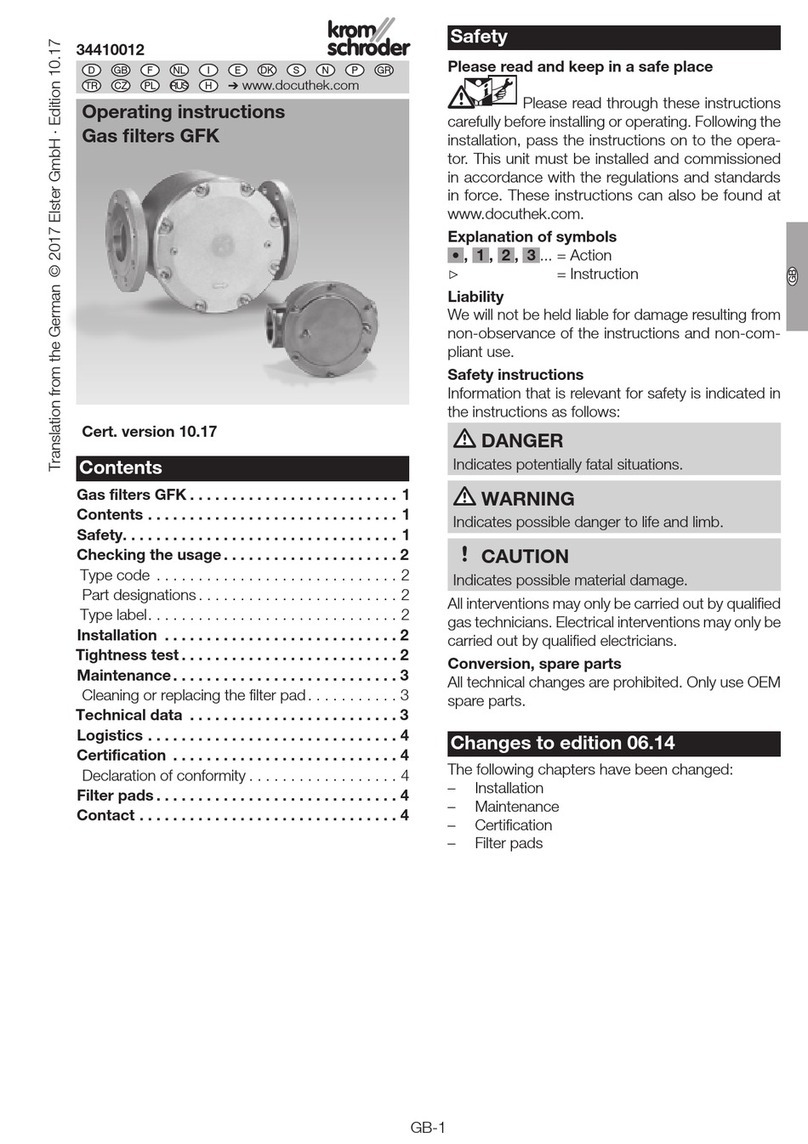
Cleaning or replacing the filter pad
1 Shut off the gas supply.
5
2 3 4
8
6
7
10 119
Clean or
replace the
filter pad.
Fit the filter
pad into the
groove in the
cover.
▷Tighten screws in a crosswise fashion and pay
attention to the torque, see table:
Type Torque [Nm]
GFK 15 5
GFK 20 5
GFK 25 8
GFK 32 8
GFK 40 8
GFK 50 8
GFK 65 8
GFK 80 20
GFK 100 20
GFK 125 60
GFK 150 60
GFK 200 80
GFK 250 80
Checking tightness and function
▷
When replacing the filter pad, the gas-filled space
in the GFK is opened. Therefore, check for tight-
ness once the filter pad has been reinstalled.
12 To be able to check the tightness, shut off the
downstream pipeline close to the gas filter.
1,2 x pu max
N2
1413
15 Tightness OK: open the pipeline.
Technical data
Gas type: natural gas, town gas, LPG (gaseous),
biologically produced methane and air.
Max. inlet pressure pu max:
GFK 15 to 250: 1 bar (14.5psig),
GFK 15R to 65R: 4 bar (60psig),
GFK 15TN to 100TN: 4 bar (60psig),
GFK 40F to 100F: 6bar (87 psig).
Storage temperature: -15 to +60°C (5 to 140°F).
Ambient temperature: -15 to +80°C (5 to 176°F).
Continuous operation at high temperatures ac-
celerates the ageing of elastomer materials.
Version to DIN 3386.
Housing material:
GFK 15 to 100: AlSi.
GFK 125 to 250: sheet steel.
Connection:
GFK..R: Rp internal thread connection to ISO7-1.
GFK..F: flanged connection to ISO 7005, PN 16.
GFK..N: NPT internal thread.
GFK..A: ANSI 150 flanged connection.
Filter pad: polypropylene fleece (standard 50μm).


