GB-4
Contact
If you have any technical questions, please contact
your local branch office/agent. The addresses are
available on the Internet or from ElsterGmbH.
We reserve the right to make technical modifications
in the interests of progress.
Elster GmbH
Strotheweg 1, D-49504 Lotte (Büren)
Tel. +49 541 1214-0
Fax +49 541 1214-370
Contact
Designed lifetime
This information on the designed lifetime is based on
using the product in accordance with these operating
instructions. Once the designed lifetime has been
reached, safety-relevant products must be replaced.
Designed lifetime (based on date of manufacture)
in accordance with EN 13611 for GFK: 10 years.
You can find further explanations in the applicable
rules and regulations and on the afecor website
(www.afecor.org).
This procedure applies to heating systems. For
thermoprocessing equipment, observe local regu-
lations.
Logistics
Transport
Protect the unit from external forces (blows, shocks,
vibration). On receipt of the product, check that the
delivery is complete, see page 2 (Part designa-
tions). Report any transport damage immediately.
Storage
Store the product in a dry and clean place.
Storage temperature: see page3 (Technical data).
Storage time: 6months before using for the first
time. If stored for longer than this, the overall service
life will be reduced by the corresponding amount of
extra storage time.
Packaging
The packaging material is to be disposed of in ac-
cordance with local regulations.
Disposal
Components are to be disposed of separately in
accordance with local regulations.
Certification
Declaration of conformity
We, the manufacturer, hereby declare that the prod-
uct GFK, marked with product ID No.0063AU1408,
complies with the essential requirements of the fol-
lowing Directives and Standards:
Directives:
– 2009/142/EC – GAD (valid until 20 April 2018)
– 2014/68/EU
Regulation:
– (EU) 2016/426 – GAR (valid from 21 April 2018)
The relevant product corresponds to the tested type
sample.
The production is subject to the surveillance proce-
dure pursuant to Directive 2009/142/EC AnnexII
paragraph 3 (valid until 20 April 2018) and to Regula-
tion (EU) 2016/426 Annex III paragraph 3 (valid from
21 April 2018).
Elster GmbH
Scan of the Declaration of conformity (D,GB)– see
www.docuthek.com
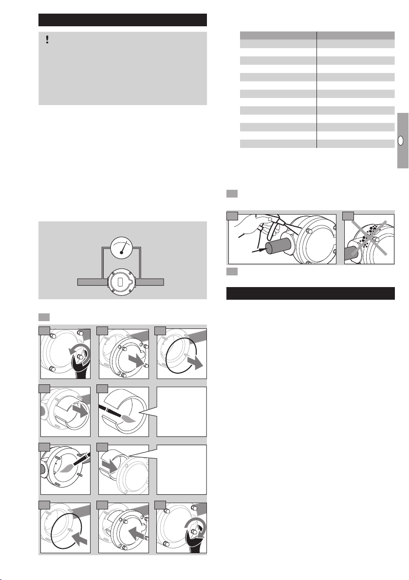
Filter pads
With 50µm separation rate
Designation Order No.
Spare parts set GFK 15/20,
10 filter pads and 10 O-rings 71935010
Spare parts set GFK 25/32,
10 filter pads and 10 O-rings 71937010
Spare parts set GFK 40/50,
5 filter pads and 5 O-rings 71939010
Spare parts set GFK 65,
1 filter pad and 1 O-ring 74923284
Spare parts set GFK 80,
1 filter pad and 1 O-ring 74923285
Spare parts set GFK 100,
1 filter pad and 1 O-ring 74923286
Filter pad GFK 125 35448581
O-ring 308x8 for GFK 125/150 03110013
Filter pad GFK 150 35448583
O-ring 308x8 for GFK 125/150 03110013
Filter pad GFK 200/250 35448584
O-ring 430x8 for GFK 200/250 03109164
▷
Filter pads with special separation rate of 10µm
for GFK15–100 on request.