1" 3" A
(76.2mm)(25.4mm) (25.4mm)
2 1/4"
(57mm)
B
(25.4mm) (76.2mm) (25.4mm)
1-15/16" B
(49.2mm)
2-1/4"
(57mm)
3" "1"1 A
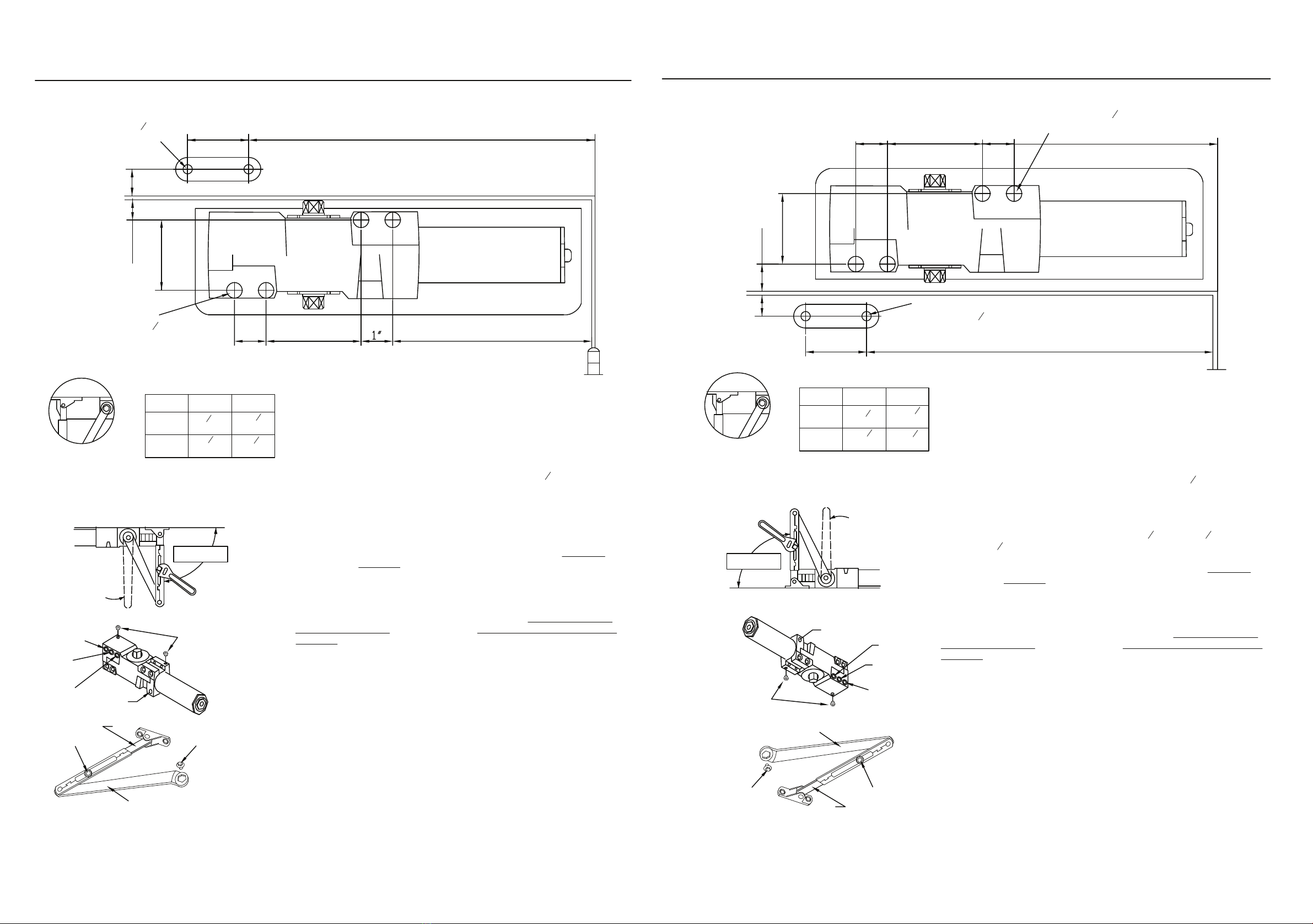
STANDARD INSTALLATION
CLOSER MOUNTED ON DOORON PULL SIDE
This drawing shown is LEFT HAND DOOR, For RIGHT HAND DOOR should be install in symmetry
2 Holes for #14
All-Purpose or 14-20
(M6X1.0) Machine
Screws.
4 Holes for #14
All-Purpose or 14-20
(M6X1.0) Machine
Screws.
INSTALLATION DIMENSIONS
OPENING
TO 100°
TO 130°
"A" "B"
7-516"
(185)
11-13 16 "
(300)
6-14"
(159)
10-13 16 "
(275)
PRELOAD TO
90°
COVER
SCREW
LATCH SPEED
SCREW
MAIN SPEED
SCREW
BACKCHECK
SCREW
FOREARM
SCREW
ROD
ARM
SCREW
MAIN ARM
Page 2 Page 3
1. Adjust spring power to match door width as indicated by chart on page 1.
2. Mount closer on door as dimensions shown. Tube end toward hinge.If pivots are
used , locate closer and shoe from CENTERLINE OF PIVOT.
(For oset pivots, please increase the marked dimensions by 18")
3.place main arm on top shaft, 90 °to closer body, insert arm screw into top of shaft
and tighten.
4.Attach shoe toframe as dimensions shown. (if more latching power is required,
rotate shoe 180°)
5.Open door and insert rod in forearm.
6. With forearm at right angle to door (90 °),insert forearm set screw and tighten.
(IF HOLD OPEN ARM IS USED, THE NUT IS ON THE TOP FOR RH DOOR AND
BOTTOM FOR LH DOOR)
REGULATION:
A ' normal ' closing time from 90 °open position to door stop position is 4-6 secs,
evenly divided between main swing speed and latch swing speed. Use socket key
(Furnished)to adjust speed. To slow m ain speed of door, turn regulating screw
nearest shaft clockwise . To slow latch speed, turn regulating screw nearest hing
clockwise.
BACKCHECK AND DELAYED ACTION
To increase back-check force, turn regulating screw nearest hin ge clockwise.
DO NOT USE ABRUPT BACKCHECK OR EXPECT DOOR CL OSER TO ACT AS
A DOOR STOP.
To Increase the Delayed closing time, turn the DA screw clockwise.
Closing time is regulated for approximately 20 seconds.
COVER
Place insert in Proper cutout, then push cover adgain door. Tighten both cover
screw securely.
HOLD OPEN ADJUSTMENT (WHEN HOLD OPEN ARM IS USED)
Loose adjusting nut, open door to designed hold open position and tighten nut.
Do not permit door to swing beyond hold open setting.
TOP JAMB INSTALLATION
CLOSER MOUNTED TOP JAMB ON PUSH SIDE OF DOOR.
This drawing shown is RIGHT HAND DOOR,
For LEFT HAND DOOR should be install in symmetry 4 Holes for #14
All-Purpose or 14-20
(M6X1.0) Machine
Screws.
2 Holes for #14
All-Purpose or 14-20
(M6X1.0) Machine
Screws.
INSTALLATION DIMENSIONS
OPENING
TO 100°
TO 130°
"A" "B"
7-516"
(185)
11-13 16 "
(300)
6-14"
(159)
10-13 16"
(275) 1. Adjust spring power to match door width as indicated by chart on page 1.
2. Mount closer on frame as dimensions shown. Tube end toward hinge.If pivots
are used , locate closer and shoe from CENTERLINE OF PIVOT.
(For oset pivots, please increase the marked dimensions by 18")
3.place main arm on top shaft 90 °to closer body, insert arm screw into top of shaft
and tighten.
4.Attach shoe to door as shown. (if more latching power is required, rotate shoe
180)
5.Open door and insert rod in forearm (For reveal 2 58"through 4 13 16" use long rod.
For reveals 4 78"to 8" use FOREARM EXTENDER (ROD) -available from dealer ).
6. With forearm at right angle to door (90 °),insert forearm set screw and tighten.
(IF HOLD OPEN ARM IS USED, THE NUT IS ON THE TOP FOR RH DOOR AND
BOTTOM FOR LH DOOR)
REGULATION:
A ' normal ' closing time from 90 open position to door stop position is 4-6 secs,
evenly divided between main swing speed and latch swing speed. Use socket key
(Furnished)to adjust speed. To slow m ain speed of door, turn regulating screw
nearest shaft clockwise . To slow latch speed, turn regulating screw nearest hing
clockwise.
BACKCHECK AND DELAYED ACTION
To increase back-check force, turn regulating screw nearest hing e clockwise.
DO NOT USE ABRUPT BACKCHECK OR EXPECT DOOR CLSOER TO ACT AS
A DOOR STOP.
To Increase the Delayed closing time, turn the DA screw clockwise.
Closing time is regulated for approximately 20 seconds.
COVER
Place insert in Proper cutout, then push cover adgain door. Tighten both cover
screw securely.
HOLD OPEN ADJUSTMENT (WHEN HOLD OPEN ARM IS USED)
Loose adjusting nut, open door to designed hold open position and tighten nut.
Do not permit door to swing beyond hold open setting.
COVER
SCREW
BACKCHECK
SCREW
MAIN SPEED
SCREW
LATCH SPEED
SCREW
MAIN ARM
ARM
SCREW
ROD
FOREARM
SCREW
PRELOAD TO
90°
11/16"
(17.5mm)
11/16"
(17.5mm)
(49.2mm)
1-15/16"
11/16"
(17.5mm)
11/16"
(17.5mm)
Delayed Action
Delayed Action
Lorem ipsum


