Krone KS2900 User manual

OperatingManual
DifferentialPressureManometer
MODELKS2900
HQ:postcode124-0023
9-6,Higashishinkoiwa3Chome,KatsushikakuTokyoJapan
TEL:+81-3-3695-5431/FAX:+81-3-3695-5698
E-Mail:[email protected]
KroneCorporation

ThisManualservestoillustratethecapabilitiesandappropriateuseofthePressureControllerKS2900.
Inappropriateuseorimproperhandlingcanleadtopotentialhazardsforpersonsandintrinsicvalues.
Therefore,anypersonentrustedwithworkingwiththedevicemustbeinstructedandawareofthepotentialrisks.
Thismanualanditssafetynoticesinparticularmustbeaddressedtowithcare.
Ifanydoubtsoccurconcerningtheproperunderstandingofanyparagraphofthismanual,pleaseconsultthe
manufacturingcompany.
Handlethismanualwithcare:
•Ithastobekeptwithinreachaslongasthedeviceisonservice.
•Ithastobehandedovertosuccessivepersonnel.
•Anysupplementseditedbythemanufacturermustbeinsertedinthismanual.
•Iftheequipmentisusedinamannernotspecifiedbythemanufacturer,theprotectionprovidedbytheequipment
maybeimpaired.
•Donotclosethepressureinputportswhenshipping,aschangesinbarometricpressurecoulddamageinstruments
withlowmeasuringranges.
•Onlytechnicalpersonnelwhoareappropriatelytrainedandauthorizedbytheoperatorofthefacilitymayassemble
theinstrumentandsetupitselectricalconnections.
•Theinstrumentmayonlybeoperatedbyappropriatelytrainedindividualswhohavebeenauthorizedbythe
operatorofthefacility.
•Pressurizedairorbreathisnottobeusedforperformancetests,asthiscoulddamageinstrumentswithlow
measurementranges.
•Measurementerrorsmayoccuriftheinstrumentisnotkeptprotectedfromsunlight.
•Specificsafetyprecautionsaregiveninindividualsectionsofthismanual.
•Altitudeupto2000m;
•ApplicablePOLLUTIONDEGREEoftheintendedenvironment(POLLUTIONDEGREE2).
•Pleasedonotapplypowerwhenconnecttheconnector
•Pleasedonotapplyleteralstressontheportsinordernottobreaktheports
Themanufacturerreservestherightstocarryonwiththedevelopmentofthisdevicewithoutdocumentingeachstep.
Pleaseaddressyourmanufacturerifyouhaveanyquestionsastotherelevanceofthismanual.
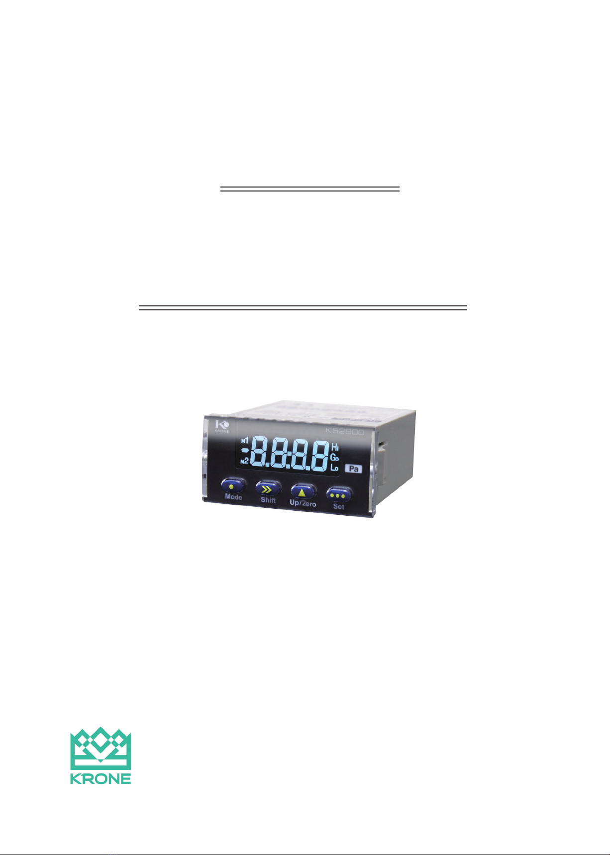
TheKS2900isaverysmallsizeddigitaldifferencepressureindicatorwhichincorporatesamono-
lithicsiliconsemiconductorpressuresensor.
Itisthebestsolutiontoverylowpressuremeasurement.
KS2900isdesignedfortheapplicationofthesemiconductordeviceequipmentsuchasCoetarDeveloper,
CleaningandFurnaceetcandhastwotransistoroutput(NPNorPNP(option))andanalogoutput4-20mAor1-5V
(Optional).
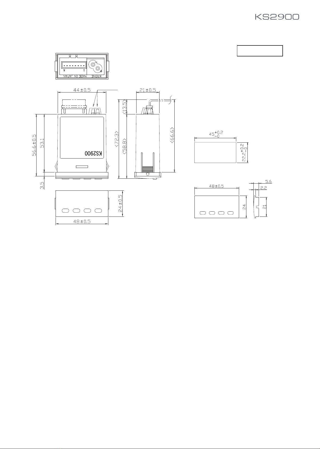
Connectortype(XHconnector(JST))
Recheckthefollowingitemsbeforeturningonthepower.
Inputandoutputwires,Iftheoutputterminalisconnectedtothepowertheinteriorcircuitwillbedamaged.
Powervoltage:Pressurerange:Beginactualoperationaftertheheatlineisactivatedforoverfiveminutes
afterthepoweristurnedon.
Excessivepressure.
Pleasedonotapplypressureexceedingthemaximumpressureasshowninthespecificationoncatalogues.
Theexcessivepressuremayaffectthesensorcharacteristicsandmaymakeaccuratemeasurementimpossible.
Insertandcontactofforeignmatter.
Apressuresensorchipisplacedinsidethepressureport.Ifforeignmattersuchaswireinsertsthrough
thepressureport,damagecouldbeoccur.
Thismustbeabsolutelyavoided.
1.OutLine
2.HandlingNote
•Onthismanual
-1-

3.Size
Dimensions:mm
-2-
3-1B8B-XH-A(8pinsconnector)
SizeforPanelcut
Panelthickness0.5to4mm
SizeforFrontcover
Portguard

4.Specification
-3-
Model
Methodofpressure
Sensor
Pressurerange
Displayaccuracy
Temperaturedrift
Medium
Element
Overpressure/Burstpressure
Powersupply
Powersupplycurrent
Settingmethod
Pressuresettingrange
Switchinghysteresis
Comparatoroutput
Output
Outputdisplay
Displayrate
Overflowdisplay
Analogoutput
Accuracy
Loadresistance
Resolution
KS2900
Differential
Semiconductorpiezoresistorswheatstonebridge
0-100〜5000Pa、±100〜±5000Pa
±1%FS±1digit,(Morethan500Pa)
100Pa=±3%FS、200Pa=±2%FS、300Pa=±1.5%FSand±1digit
Max±0.1%F.S./℃(0〜50℃)
Air,non-corrosivedrygasses(dustisnotpermitted)
Semiconductorsilicon
0-100〜1000、±100〜±1000:5kPa/10kPa
0-2000〜5000、±2000〜±5000:7.5kPa/15kPa
12/24VDC(±10%)
45mA(within20mA-Aout,Backlight:on,withoutPNPoutputcurrent)
Digitalsettingbyfrontpanel
HiandLo0-100%F.S(min:1Pa)
0-100%(min:1Pa)
Hi,Go,Looutput
[NPNopencorrector]
SinkCurrent:100mAless/Resistiveload(Vsat:1.35V)
Maximumapplyingvoltage:35VDC
[PNPtransistoroutput](option)
Outputvoltagefollowspowersource
Sourcecurrent:80mAless(Voltagedrops:2V)
Maximumapplyingvoltage:35VDC
7segmentLCD(withBacklight)
Selectablefrom0.1/0.5/1/2/5/10sec.
DisplayBlinkatpressurein≧110%F.S.
4-20mAor1-5V(Option)
±1.5%F.S〜
standerd=250Ω,Max:350Ω
1Pa
Display Comparator
Analog
output

0-50℃(Notbefreeze)
35-85%
-20℃〜+70℃
Indoor
upto2000m
POLLUTIONDEGREE2
IP40
Notlowerthan5minute
0.1sec
Notlowerthan100MΩ(Acrossthepanelandterminals、DC500V)
500VAC(Acrossthepanelandterminals、50/60Hz1minute)
maxφ3.5mm(+)forhighpressure,(-)forlowpressure
(8pinsconnector)JST:B8B-XH-A
ABS(Case)
24(H)x48(W)x66(D)mm:B8B-XH-A
Panelmount
None
Approx.40g
RoHS
CE:EN61326-1-2013
UL:E361798
Samplingrate
Insulationresistance
withstandvoltage
Pressureport
Electricconnection
Material
Dimensions
Mounting
Mountngerror
Weight
Tests/Admissions
Operatingtemperaturerange
HumidityLimits
Storagetemperaturerange
Operatingenvironment
Altitude
POLLUTIONDEGREE
Protectionstandard
Warminguptime
Item Specification
-4-
environment

Pinnumber Terminalname Functioncontents
12345678
Pin1
Pin2
Pin3
Pin4
Pin5
Pin6
Pin7
Pin8
Hi
Go(Good)
Lo
GND(COM)
ACOM(-)
AOUT(+)
GND(COM)
V(+)
HiAlarmoutput
NPNopencorrectoroutput
PNPtransistoroutput(option)
Gosignaloutput
NPNopencorrectoroutput
PNPtransistoroutput(option)
LoAlarmoutput
NPNopencorrectoroutput
PNPtransistoroutput(option)
Power(common=GND)
Analogoutput(common)
Analogoutput(out)
Power(common=GND)
Powersupply(DC12/24V)
Port(+)
Port(−) JST
:B8B-XH-A(8pins)
5.Terminal description
5-1B8B-XH-A(8pinsconnector)
-5-
6. Application
6-1B8B-XH-A(8pinsconnector)
ApplicationSchematic/NPNopencorrectoroutput
ApplicationSchematic/PNPtransistoroutput(option)
*AnalogoutputRecommendationTerminationresistance
4-20mA:250Ω(max.:350Ω)
1-5V:10kΩ(min.:1kΩ)
*P1:connectorcable=Option
Vcc
Vcc
Hi
Go
Lo
com
AO-
AO+
GND
12/24VDC
4-20mAout
Lo
Hi
Go
V
Fuse/1A
A
DC12/24V
Hi
Go
Lo
250
B
EC
Relay-Hi2
3
2 4
5
1
B
EC
B8B-XH-A
1
2
3
4
5
6
7
8
1
2
3
4
5
6
7
8
Diode
Diode
Diode
Relay-Lo1
3
2 4
5
1
Relay-Go2
3
2 4
5
1
B
EC
−
+
Vcc
Vcc
V
DC12/24V
4-20mAout
Hi
Go
Lo
Lo
Hi
Go
A
Hi
Go
Lo
com
AO-
−
+AO+
GND
12/24
VDC
B8B-XH-A
1
2
3
4
5
6
7
8
1
2
3
4
5
6
7
8
2
1 3
Relay-Lo2
3
2 4
5
1
2
1 3
2
1 3
Relay-Go1
3
2 4
5
1
Relay-Hi1
3
2 4
5
1
250
Diod6
Diod8
Diod5
P1
P1

[1]7segmentLCD
[5]MODEKey
[6]SHIFTKey
[7]UP/ZeroKey
[8]SETKey
[2]HiLCD
[3]GoLCD
[4]LoLCD
7. Operaing components
-6-
7-1Display
7-2Keyfunctions(basic)
Eg.
Backtomeasurementmode
Shift
Changethevalue
Returnkey
Jumptosettingmode(M1,M2)
Zeroadjustment
+
(Over5sec.)→
Duringoperation,displayreturnstomeasuringmodeafter1min.ifnoKeyoperationdone.
DuringHiorLosettingmode,measuringfunctionisgoingon.
Measure
Display
Hiset
Display
HiBlink
Loset
Display
LoBlink
SETKey SETKey
SETKey
1min. 1min.
+

Indicates” Alarmsettingmode”
TosetalarmpointforHi
1_HindicatesHisetting,1_LindicatesLowsetting.
Alarmconditionof1_Hor1_ListobeselectedintheConditionsettingmode.
Figureshiftedbyandsetbykey.
Valuecanbesetwithinrangeof−9999〜+9999digits.
Duringsettingoperation,HiLCDdisplaylighting.
TosetalarmpointforLo
2_HindicatesHisetting,2_LindicatesLowsetting.
Alarmconditionof2_Hor2_ListobeselectedintheConditionsettingmode.
Figureshiftedbyandsetbykey.
Valuecanbesetwithinrangeof−9999〜+9999digits.
Duringsettingoperation,LoLCDdisplaylighting.
Indicates” Alarmconditionsettingmode”
TosetalarmconditionforHi.
Setbykey.
1_H:tosetHialarmpoint.
1_L:tosetLowalarmpoint.
Duringsettingoperation,HiLCDdisplaylighting.
TosethysteresisforHioutputtoreturnfromOntoOff.
Figureshiftedbykeyandsetbykey.
DuringsettingoperationHiLCDdisplaylighting.
ModechangeforPositiveLogicorNegativeLogic
TosetalarmconditionforLo.
Setbykey.
2_H:tosetHialarmpoint.
2_L:tosetLowalarmpoint.
TosethysteresisforLooutputtoreturnfromOntoOff.
Figureshiftedbykeyandsetbykey.
DuringsettingoperationLoLCDdisplaylighting.
ModechangeforPositiveLogicorNegativeLogic
TosetdelaytimeforHiandLooutputtomovefromOfftoOnorOntoOff.
on.d:TosetdelaytimetomovefromOfftoOn.
oFF.d:TosetdelaytimetomovefromOntoOff.
Setbykey.
Delaytimecanbesetwithinrangeof0〜9999sec.
Figureshiftedbykeyandsetbykey.
Alarmactiveornonactivemode
Backlightblinkornotwhenalarmvalueonthedisplay
8. Setting menu
-7-
DescriptionMenuDisplay

Indicates” OperationConditionsettingmode”
ManualZEROsetting ON/OFFmode(key)
ZEROdisplayunder5%FS(Adjustable)
Samplingrate0.1sec.
Displayrateselectablefrom0.1/0.5/1/2/5/10sec.(key)
ZEROsuppressON/OFF
SmallestdigitZEROON/OFF(key)
ModeprotectionON/OFF
ActiveornonactiveforAnalogoutput
Analogoutputmode
thr:outputevery0.1sec.
diSP:SynchronizewithDisplay
+(andover3sec.)
+(andover3sec.)→→
Backlighttimertoautooff0sec.to8888sec.(8888means∞)
SamplingaveragemodeDisplayshowingresultofsettingaverage.
WhenperformingserialcommunicationusingPressON/OFF
9. Command
-8-

10. Parameter table
-9-
㻿㼑㼠㻌㼒㼛㼞㻌㻿㼔㼕㼒㼠㻛㼁㼜㻌㼗㼑㼥 㻿㼑㼠㻌㼒㼛㼞㻌㻿㼔㼕㼒㼠㻛㼁㼜㻌㼗㼑㼥
㻖㻕㻌㻝䠻㻝㻩㻌㻼㼛㼟㼕㼠㼕㼢㼑㻌㻸㼛㼓㼕㼏
㻝䠻㻜㻌㻩㻌㻺㼑㼓㼍㼠㼕㼢㼑㻌㻸㼛㼓㼕㼏
㻖㻕㻌㻞䠻㻝㻩㻌㻼㼛㼟㼕㼠㼕㼢㼑㻌㻸㼛㼓㼕㼏
㻞䠻㻜㻌㻩㻌㻺㼑㼓㼍㼠㼕㼢㼑㻌㻸㼛㼓㼕㼏
㻖㻕㻌㻜㻚㻜㻌㼠㼛㻌㻡㻚㻜㻑㻌㼙㼍㼤㻚
䠴㻌䠴㻌䠴㻌䠴
㻸㼛㻌㻰㼕㼞㼑㼏㼠㼕㼛㼚 㻸㼛㻌㻴㼥㼟㼠㼑㼞㼑㼟㼕㼟
䠴㻌䠴㻌䠴㻌䠴
㻸㼛㻌㻻㼡㼠㼜㼡㼠㻌㻸㼛㼓㼕㼏
㻻㼡㼠㼜㼡㼠㻌㻿㼑㼘㼑㼏㼠 㻮㼘㼕㼚㼗㻳㼛㻌㻻㼡㼠㼜㼡㼠㻌㻸㼛㼓㼕㼏 㻰㼑㼘㼍㼥㻌㼀㼕㼙㼑
㻹㼑㼟㼡㼞㼙㼑㼚㼠
㻰㼕㼟㼜㼘㼍㼥
㻯㼛㼙㼜㼍㼞㼕㼟㼛㼚
㼂㼍㼘㼡㼑㻌㻿㼑㼠
㻯㼛㼙㼜㼍㼞㼕㼟㼛㼚
㻯㼛㼚㼐㼕㼠㼕㼛㼚㻌㼟㼑㼠
㻻㼜㼑㼞㼍㼠㼕㼛㼚
㻯㼛㼚㼐㼕㼠㼕㼛㼚㻌㻿㼑㼠
㻭㼚㼍㼘㼛㼓
㻻㼡㼠㼜㼡㼠㻌㻿㼑㼘㼑㼏㼠
㻸㼛㻌㼜㼛㼕㼚㼠㻌㼟㼑㼠
䠴㻌䠴㻌䠴㻌䠴
㻴㼕㻌㼜㼛㼕㼚㼠㻌㼟㼑㼠
䠴㻌䠴㻌䠴㻌䠴
㻴㼕㻌㻰㼕㼞㼑㼏㼠㼕㼛㼚 㻴㼕㻌㻴㼥㼟㼠㼑㼞㼑㼟㼕㼟 㻴㼕㻌㻻㼡㼠㼜㼡㼠㻌㻸㼛㼓㼕㼏
㼆㼑㼞㼛㻌㼍㼐㼖㼡㼟㼠 㻸㼛㼣㻌㻯㼡㼠㼠㼕㼚㼓㻌㻾㼍㼠㼑
㻻㼡㼠㼜㼡㼠㻌㼙㼛㼐㼑
㻿㼍㼙㼜㼘㼕㼚㼓㻌㻾㼍㼠㼑
㼆㼑㼞㼛㻌㻿㼡㼜㼜㼞㼑㼟㼟 㻸㼍㼟㼠㻌㻰㼕㼓㼕㼠㻌㻲㼕㼤 㻼㼞㼛㼠㼑㼏㼠㼕㼛㼚
㻰㼕㼟㼜㼘㼍㼥㻌㻾㼍㼠㼑
㻖㻕㻌
䠴㻌䠊䠴
䠄䠂䠅
䠌䠊䠍㻌䡚㻌䠍㻌䠌
䠄㼟㼑㼏䠅
䠄㼟㼑㼏䠅
䠴㻌䠴㻌䠴㻌䠴
+ (>3sec)
10-1Mode1Parametertable
Default
Selectable
㻿㼑㼘㼑㼏㼠㻌㼒㼛㼞㻌㼁㼜㻌㼗㼑㼥
㻖㻕㻌㻿㼑㼠㻌㼢㼍㼘㼡㼑㻌㼙㼡㼟㼠㻌㻌㻴㼕㻌㼜㼛㼕㼚㼠㻌䠚㻌㻸㼛㻌㼜㼛㼕㼚㼠㻖㻕㻌㻖㻕㻌
㻖㻕㻌㻳䠻㻝㻩㻌㻼㼛㼟㼕㼠㼕㼢㼑㻌㻸㼛㼓㼕㼏
㻖㻕㻌㼟㼑㼠㻌㼒㼛㼞㻌㻜㻜㻜㻜䡚㻥㻥㻥㻥㼟㼑㼏㻚
㻖㻕㻌㼛㻲㻲㻚㼐㻌㻦㻌㻾㼑㼍㼏㼠㼕㼢㼑㻌㼠㼕㼙㼑㻌㼍㼒㼠㼑㼞㻌㼘㼑㼟㼟㻌㼠㼔㼍㼚㻌㼟㼑㼠㻌㼢㼍㼘㼡㼑㻚
㻌㻌㻌㻌㻌㻌㼛㼚㻚㼐㻌㻦㻌㻾㼑㼍㼏㼠㼕㼢㼑㻌㼠㼕㼙㼑㻌㼍㼒㼠㼑㼞㻌㼙㼛㼞㼑㻌㼠㼔㼍㼚㻌㼟㼑㼠㻌㼢㼍㼘㼡㼑㻚
㻳䠻㻜㻌㻩㻌㻺㼑㼓㼍㼠㼕㼢㼑㻌㻸㼛㼓㼕㼏
㻖㻕㻌
㻖㻕㻌
㻹㼑㼟㼡㼞㼙㼑㼚㼠
㻿㼑㼘㼑㼏㼠㻌㼒㼛㼞㻌㼁㼜㻌㼗㼑㼥㻿㼑㼠㻌㼒㼛㼞㻌㻿㼔㼕㼒㼠㻛㼁㼜㻌㼗㼑㼥
㻿㼑㼘㼑㼏㼠㻌㼒㼛㼞㻌㼁㼜㻌㼗㼑㼥 㻿㼑㼘㼑㼏㼠㻌㼒㼛㼞㻌㼁㼜㻌㼗㼑㼥㻿㼑㼠㻌㼒㼛㼞㻌㻿㼔㼕㼒㼠㻛㼁㼜㻌㼗㼑㼥
㻿㼑㼘㼑㼏㼠㻌㼒㼛㼞㻌㼁㼜㻌㼗㼑㼥 㻿㼑㼘㼑㼏㼠㻌㼒㼛㼞㻌㼁㼜㻌㼗㼑㼥 㻿㼑㼘㼑㼏㼠㻌㼒㼛㼞㻌㼁㼜㻌㼗㼑㼥 㻿㼑㼘㼑㼏㼠㻌㼒㼛㼞㻌㼁㼜㻌㼗㼑㼥
㻖㻕㻌㼟㼑㼘㼑㼏㼠㻌㼒㼞㼛㼙㻌㻜㻚㻝䚸㻜㻚㻡䚸㻝䚸㻞䚸㻡䚸㻝㻜㻌㻔㼟㼑㼏㻕
㻖㻕㻌㻾㼑㼟㼜㼛㼚㼟㼑㻌㼠㼕㼙㼑㻌㼛㼒㻌㼠㼔㼑㻌㼍㼚㼍㼘㼛㼓㻌㼛㼡㼠㼜㼡㼠㻚
㼐㻵㻿㻼㻌㻦㻌㻰㼑㼜㼑㼚㼐㼟㻌㼛㼚㻌㼠㼔㼑㻌㼟㼍㼙㼜㼘㼕㼚㼓㻌㼟㼜㼑㼑㼐㻌㼛㼒㻌㼠㼔㼑㻌㼐㼕㼟㼜㼘㼍㼥㻚
㼠㻴㼞㻌㻦㻌㻜㻚㻝㻌㼟㼑㼏㻚
㻿㼑㼘㼑㼏㼠㻌㼒㼛㼞㻌㼁㼜㻌㼗㼑㼥 㻿㼑㼠㻌㼒㼛㼞㻌㻿㼔㼕㼒㼠㻛㼁㼜㻌㼗㼑㼥 㻿㼑㼘㼑㼏㼠㻌㼒㼛㼞㻌㼁㼜㻌㼗㼑㼥 㻿㼑㼘㼑㼏㼠㻌㼒㼛㼞㻌㼁㼜㻌㼗㼑㼥
㻿㼑㼘㼑㼏㼠㻌㼒㼛㼞㻌㼁㼜㻌㼗㼑㼥 㻿㼑㼘㼑㼏㼠㻌㼒㼛㼞㻌㼁㼜㻌㼗㼑㼥
㻿㼑㼘㼑㼏㼠㻌㼒㼛㼞㻌㼁㼜㻌㼗㼑㼥
㻿㼑㼘㼑㼏㼠㻌㼒㼛㼞㻌㼁㼜㻌㼗㼑㼥
㻿㼑㼘㼑㼏㼠㻌㼒㼛㼞㻌㼁㼜㻌㼗㼑㼥
㻖㻕㻌

-10-
10-2Mode2Parametertable
㻌
+ (>3sec)
䠌㻌䡚㻌䠎㻌䠑㻌䠑
㻹㼛㼢㼕㼚㼓
㻭㼢㼑㼞㼍㼓㼑㻌㻯㼥㼏㼘㼑
䠄㼟㼑㼏䠅
㻮㼍㼏㼗㼘㼕㼓㼔㼠
㻯㼛㼚㼠㼕㼚㼡㼍㼚㼏㼑㻌㼀㼕㼙㼑
㻹㼑㼍㼟㼡㼞㼑㼙㼑㼚㼠
㻹㼑㼍㼟㼡㼞㼑㼙㼑㼚㼠
㻰㼕㼟㼜㼘㼍㼥
㻰㼕㼟㼜㼘㼍㼥
㻿㼑㼘㼑㼏㼠㻌㼒㼛㼞㻌㼁㼜㻌㼗㼑㼥
㻿㼑㼘㼑㼏㼠㻌㼒㼛㼞㻌㼁㼜㻌㼗㼑㼥
㻿㼑㼠㻌㼒㼛㼞㻌㻿㼔㼕㼒㼠㻛㼁㼜㻌㼗㼑㼥
㻿㼑㼞㼕㼍㼘㻌㻻㼡㼠㼜㼡㼠
㻖㻕㻌㻿㼑㼠㻌㼒㼛㼞㻌㻜㻜㻝䡚㻞㻡㻡㻌㼏㼥㼏㼘㼑㻚㻔㻜㻜㻝㻌㼙㼑㼍㼚㼟㻌㼣㼕㼠㼔㼛㼡㼠㻌㼙㼛㼢㼕㼚㼓㻌㼍㼢㼑㼞㼍㼓㼑㻚㻌㻕
㻖㻕
㻖㻕
㻖㻕㻌㻤㻤㻤㻤㻌㼕㼟㻌㼕㼚㼒㼕㼚㼕㼠㼑
Default
Selectable

40154-0017-12
KRONEwarrantstheProductstobefreeofdefectsinmaterialsandworkmanshipforaperiodofoneyearfromthe
dateofshipment.
IfanymodelsorsampleswereshowntoBuyer,suchmodelsorsampleswereusedmerelytoillustratethegeneral
typeandqualityoftheProductsandnottorepresentthattheProductswouldnecessarilyconformtosaidmodelsor
samples.
AnyProductsfoundtobedefectivemustbeshippedtoKRONEwithallshippingcostspaidbyBuyerorofferedto
KRONEforinspectionandexamination.
UponexaminationbyKRONE,atitssoleoption,willrefundthepurchasepriceof,orrepairorreplaceatnocharge
anyProductsfoundtobedefective.
ThiswarrantydoesnotapplytoanydefectsresultingfromanyactionofBuyer,includingbutnotlimitedtoimproper
installation,improperinterfacing,improperrepair,unauthorizedmodification,misapplicationandmishandling,suchas
exposuretoexcessivecurrent,heat,coldness,moisture,vibrationoroutdoorsair.
Componentswhichweararenotwarranted.Pressureportportionisthinner.Pleasebeawareofthedamagecaused
byoverload.
KRONEispleasedtooffersuggestionsontheuseofitsvariousProducts.
Theyareonlysuggestions,anditisBuyer'sresponsibilitytoascertainthefitnessoftheProductsforBuyerʼsintended
use.
KRONEwillnotberesponsibleforanydamagesthatmayresultfromtheuseoftheProducts.
14. Warranty
-11-
Table of contents
Other Krone Measuring Instrument manuals