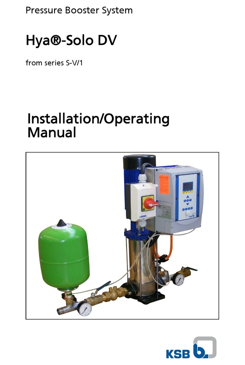
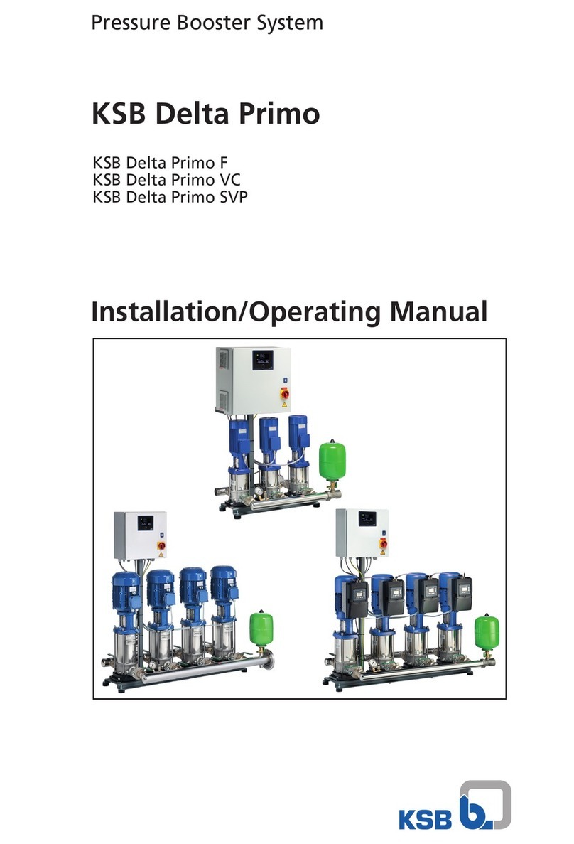
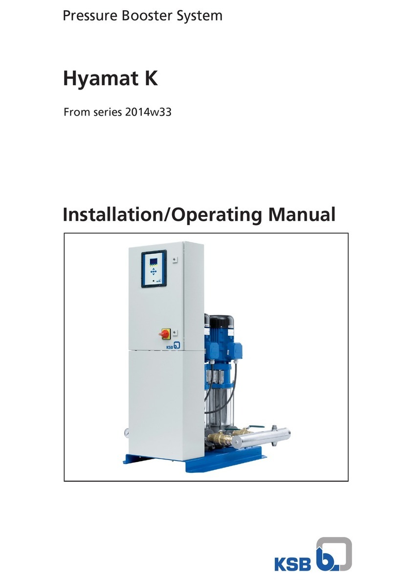
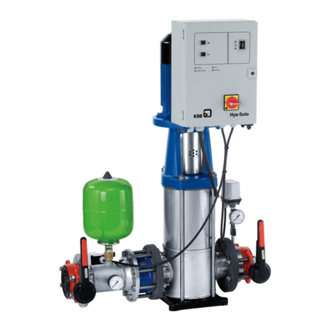
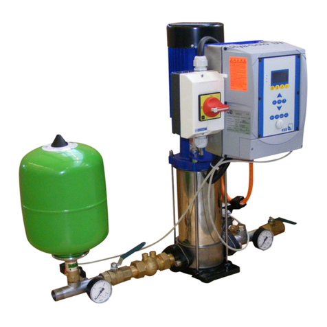
KSB Hyamat K Series Installation instructions

Hyamat K
Original operating manual
1952.86/3-10
Fully electronic pressure boosting systems
with 2 - 6 vertical high-pressure pumps
from series S-R
These operating instructions contain
fundamental information which must be
complied with during installation, operation and
maintenance. For this reason, they must be read
and understood by the installing personnel and
the responsible technical staff / operators before
the machine / unit is installed and commissioned.
They must always be kept available at the place
of installation for future reference.
Works No.:
Type series: Hyamat K

Hyamat K
2

Hyamat K
3
Contents
Page Page
1 General 4
2 Safety 4
2.1 Marking of instructions in the manual 4
2.2 Personnel qualification and training 4
2.3 Non-compliance with safety instructions 4
2.4 Safety awareness 4
2.5 Safety instructions for the operator/user 4
2.6 Safety instructions for maintenance, inspection and
installation work 4
2.7 Unauthorized modification and manufacture of
spare parts 5
2.8 Unauthorized modes of operation 5
3 Transport and interim storage 5
4 Description 5
4.1 General description 5
4.2 Configuration and function 5
4.2.1 Configuration 5
4.2.2 Function 5
4.3 Dry running protection (supplementary equipment) 6
4.4 Manual mode (supplementary equipment) 6
4.5 Control cabinet 6
4.6 Flow diagram 7
5 Installation at site 8
5.1 Readiness for operation 8
5.2 Installation and location as per DIN 1988 8
5.3 Piping 8
5.4 Foundation 8
5.5 Installation 8
5.6 Acoustic cladding (supplementary equipment) 8
5.7 Installing an expansion joint 8
5.8 Installing a pressure reducer 8
5.9 Location and installation of unpressurized inlet tanks 9
5.9.1 Location 9
5.9.2 Installation 9
5.10 Valves and fittings 9
5.11 Noise characteristics 9
6 Connection to power supply 9
6.1 Electric wiring 9
6.2 Selecting a power supply cable 9
6.2.1 Sizing the power supply cable 9
6.3 Protective measures 9
6.4 Temperature requirements 9
6.5 Humidity requirements 9
6.6 Installation altitude 9
6.7 Pollution exposure 9
6.8 Checking the voltage 9
6.9 Logic / circuit diagrams 9
6.10 Motor protection switch 9
6.11 Potential equalization 10
7 Commissioning / start-up 10
7.1 Preparations for commissioning / start-up 10
7.2 Test run 10
7.3 Checking the direction of rotation 10
7.4 Functional description / Automatic mode 10
7.5 Starting the unit 11
7.5.1 Function of the control panel 11
7.5.2 Menu structure 13
7.6 Monitoring 14
7.7 Parameter list 15
7.8 Alerts and warnings – overview 21
7.9 Adjusting the settings 22
7.9.1 Setting the set pressure 22
7.9.2 Further settings 22
7.10 Connection remote-OFF 22
7.11 Connection fire alarm 22
7.12 Shutdown 22
8 Dismantling / reassembling the pumps 22
9 Returning to service 22
10 Maintenance 22
10.1 Operation monitoring 22
11 Work on the control cabinet 22
12 Inspection 23
13 Check list 23
14 Pre-set pressure 23
15 Electrical performance data 24
16 Shutoff head 25
17 Trouble-shooting 26
18 System schematic, List of components 28
19 Annex 32

Caution
Hyamat K
4
1 General
Configuration and function of the Hyamat pressure boosting
units are in accordance with DIN 1988 stipulations.
These operating instructions are intended to facilitate
familiarization with the unit and its designated use.
The manual contains important information for reliable, proper
and efficient operation. Compliance with the operating
instructions is of vital importance to ensure reliability and a long
service life of the unit and to avoid any risks.
These operating instructions do not take into account local
regulations; the operator must ensure that such regulations are
strictly observed by all, including the personnel called in for
installation.
This pump / unit must not be operated beyond the limit values
for the fluid handled, capacity, speed, density, pressure,
temperature and motor rating specified in the technical
documentation. Make sure that operation is in accordance with
the instructions laid down in this manual or in the contract
documentation.
The name plate indicates the type series / size, main operating
data and works / serial number; please quote this information
in all queries, repeat orders and particularly when ordering
spare parts.
If you need additional information or instructions or if the device
is damaged, contact your nearest KSB customer service
centre.
2 Safety
These operating instructions contain important information
which must be observed when installing, operating and
maintaining the unit. Therefore this operating manual must be
read and understood both by the installing personnel and the
responsible trained personnel / operators prior to installation
and commissioning, and it must always be kept close to the
location of operation of the machine / unit for easy access.
Not only must the general safety instructions laid down in this
chapter on ”Safety” be complied with, but also the safety
instructions outlined under specific headings.
2.1 Marking of instructions in the manual
The safety instructions contained in this manual whose
non-observance might cause hazards to persons are specially
marked with the general hazard sign, namely
safety sign to ISO 7000 -- 0434.
The electrical danger warning sign is
safety sign to IEC 417 -- 5036
The word
is used to introduce safety instructions whose non-observance
may lead to damage to the equipment and its functions.
Instructions attached directly to the machine, e.g.
-- arrow indicating the direction of rotation
-- markings for fluid connections
must always be complied with and be kept in a perfectly legible
condition at all times.
2.2 Personnel qualification and training
All personnel involved in the operation, maintenance,
inspection and installation of the unit must be fully qualified to
carry out the work involved. Personnel responsibilities,
competence and supervision must be clearly defined by the
operator. If the personnel in question does not already possess
the requisite know-how, appropriate training and instruction
must be provided. If required, the operator may commission the
manufacturer / supplier to take care of such training. In addition,
the operator is responsible for ensuring that the contents of the
operating instructions are fully understood by the responsible
personnel.
2.3 Non-compliance with safety instructions
Non-compliance with safety instructions can jeopardize the
safety of personnel, the environment and the machine / unit
itself. Non-compliance with these safety instructions will also
lead to forfeiture of any and all rights to claims for damages.
In particular, non-compliance can, for example, result in:
-- failure of important machine/system functions,
-- failure of prescribed maintenance and servicing practices,
-- hazard to persons by electrical, mechanical and chemical
effects,
-- hazard to the environment due to leakage of hazardous
substances.
2.4 Safety awareness
It is imperative to comply with the safety instructions contained
in this manual, the relevant national health and safety
regulations and the operator’s own internal work, operation and
safety regulations.
2.5 Safety instructions for the operator / user
-- Any hot or cold components that could pose a hazard must
be equipped with a guard by the operator.
-- Guards which are fitted to prevent accidental contact with
moving parts (e.g. coupling) must not be removed whilst the
unit is operating.
-- Leakages (e.g at the shaft seal) of hazardous fluids handled
(e.g. explosive, toxic, hot) must be contained so as to avoid
any danger to persons and the environment. All relevant
laws must be heeded.
-- Electrical hazards must be eliminated. (In this respect refer
to the relevant safety regulations applicable to different
countries and / or the local energy supply companies.)
2.6 Safety instructions for maintenance,
inspection and installation work
The operator is responsible for ensuring that all maintenance,
inspection and installation work be performed by authorized,
qualified specialist personnel who are thoroughly familiar with
the manual.
Work on the machine / unit must be carried out only during
standstill. The shutdown procedure described in the manual for
taking the unit out of service must be adhered to without fail.
Pumps or pump units handling fluids injurious to health must be
decontaminated.

Caution
Hyamat K
5
Immediately following completion of the work, all
safety-relevant and protective devices must be re-installed
and / or re-activated.
Please observe all instructions set out in the chapter on
”Commissioning / start-up” before returning the unit to service.
2.7 Unauthorized modification and
manufacture of spare parts
Modifications or alterations of the equipment supplied are only
permitted after consultation with the manufacturer. Original
spare parts and accessories authorized by the manufacturer
ensure safety. The use of other parts can invalidate any liability
of the manufacturer for resulting damage.
2.8 Unauthorized modes of operation
The warranty relating to the operating reliability and safety of
the unit supplied is only valid if the equipment is used in
accordance with its designated use (see section 4). The limits
stated in the data sheet must not be exceeded under any
circumstances.
3 Transport and interim storage
The package unit is packaged on pallets or in wooden crates
and wrapped in plastic foil for shipping and interim storage. All
connecting points are capped. It is imperative that the
shipping / handling instructions shown on the package be
followed.
The unit must be protected against frost.
If upon unpackaging the unit you should discover that the
package has been damaged by dropping or some other form of
mechanical impact, please carefully inspect the unit itself for
possible damage and inform the freight forwarder / KSB’s
customer service, even if you have not been able to detect any
such damage.
Once the unit has been removed from the package, it must be
stored in accordance with the location and installation
instructions (see Installation and location).
4 Description
4.1 General description
The fully electronic pressure boosting package units are
supplied ready for connection.
The equipment circuitry allows both direct and indirect
connection to the water supply system.
For combined use as drinking water supply and fire protection
system, Hyamat K can be installed as an interconnected
system in accordance with DIN 1988, Part 5.
The equipment must be operated and maintained in
accordance with DIN 1988 (DVGW) so as to ensure
uninterrupted reliability of water supply, without causing
disturbances in the public water supply or other consumer
supply systems.
The instructions put forth in DIN 1988 must be adhered to for
connection to the public water supply system; any applicable
water utility or fire protection regulations must also be
complied with.
Furthermore, local conditions must be taken into account (for
example excessive or very unsteady supply pressure requiring
the installation of a pressure reducer).
4.2 Configuration and function
4.2.1 Configuration
Between 2 and 6 vertical high-pressure pumps (for description
and function, please refer to the pump’s Operating Instructions)
are arranged on a baseplate.
Each pump is installed on its own anti-vibration mounts.
Pumps connected in series are coupled by stainless steel
pipes.
On the system side, a combined non-return and shut-off valve
(KFR) or a swing check valve and a shut-off butterfly valve are
fitted downstream of each pump.
On the suction side, a ball valve or a shut-off butterfly valve are
fitted upstream of each pump as a service valve.
The shut-off elements permit dismantling of individual pumps
without having to drain the pipework. The discharge side
non-return valve ensures that the system remains filled with
water and prevents backflow through the pumps.
Both distributor pipes feature additional connections for
draining, venting and installation of various dry running
protection devices.
The surge vessel (accumulator) is fitted with an isolating valve.
It compensates discharge-side peak pressures and, together
with the minimum operating period, limits the pumps’ switching
frequency.
Hyamat K units are switched on as a function of pressure. To
this effect, a pressure transmitter is fitted in the discharge-side
piping.
Depending on the number and performance of the pumps, the
completely wired control cabinet is either supplied mounted on
the baseplate or as a free-standing cabinet.
Only additional and special equipment is already fitted on the
system.
Accessories such as expansion joints, tanks, accumulators,
pressure reducers etc. are supplied with the unit but are not
mounted.
The unit is driven by surface-cooled three-phase squirrel-cage
motors, 50 Hz, air-cooled, 2-pole, KSB standardized motor with
main dimensions to IEC. Other motor makes after consultation
with KSB,
up to 2.2 kW 220--240 V/380--420 V,
from 3 kW 380--420 V/660--725 V
enclosure IP 55, thermal class F, up to 4 kW design V18,
from 5.5 kW design V1, all motors>3kWwithPTCthermistor.
4.2.2 Function
The Hyamat unit is switched on and off as a function of the
pressure. The start-up pressure pEand the switch-off pressure
pAare derived from the adjustable set value psoll and the
adjustable hysteresis.
pE=p
soll -- hysteresis, pA=p
soll + hysteresis.
Automatic mode
The unit consisting of 2 to 6 pumps starts the first pump when
the pressure falls below the start-up pressure pE.
When the start-up pressure is reached, a minimum operating
period of 3 minutes is activated.
If this pump meets the current demand and if a pressure > pE
and < pAis maintained, the pump operates until the demand
drops and the switch-off pressure pAis reached.
If the first pump cannot meet the demand, the pressure will fall
below pEagain, and the next pump available is started after a
cut-in delay period of 2 seconds.
This routine is repeated until all pumps are running.
If the unit has been correctly selected in accordance with DIN
1988, the demand will be covered without using the stand-by
pump.
As demand decreases, the pumps are automatically
sequenced out after their minimum operating period and a
cut-out delay of 2 seconds. The pump that was started up first
will be switched off first.
In order to ensure equal distribution of pump operating hours,
the pumps will be changed for the next start-up cycle.
The operating status is displayed via LEDs.

Caution
Caution
Hyamat K
6
4.3 Dry running protection (supplementary
equipment)
A pressure transmitter or manometric switch with pressure
gauge may be fitted in the suction-side distributor pipe.
Pressure
transmitter: Set with parameter 3--4--1--1 and
3--4--1--2
Manometric switch:
-- The inlet pressure is set by means of a
manometric switch.
If the pressure drops below the set inlet pressure, the unit is
switched off after 7 seconds due to lack of water. The unit is
automatically switched on again as soon as the lack-of-water
condition has been remedied or sufficient inlet pressure is
available again.
For indirect connection to an inlet tank and an inlet pressure
below 0.5 bar, the inlet must be monitored by level monitoring
(for example with a dry running protection set, see
Accessories).
If other dry running protection devices are retrofitted (see
Accessories), the instructions in the circuit diagram must
be observed.
Inadequate connection may damage the unit.
On pressure boosting units ordered without dry running
protection the terminal intended for the dry running device
is open.
If no dry running protection device is connected when
commissioning takes place, the unit will be shut down
after 7 seconds.If the dry running protection terminal is
deactivated by means of a bridge, the operator shall
assume responsibility for any dry running that might
occur.
4.4 Manual mode
Each pump can be started up in manual mode for 10 seconds
via the control unit (parameter 1--2--1). If fitted with
manual-0-automatic switches (supplementary equipment), the
pumps can also be started up in manual mode by means of the
manual-0-automatic switches. The pumps are then connected
directly to the mains, independently of the control unit.
For this mode of operation no pressure control and no
lack-of-water monitoring will be effected.
Furthermore, in manual mode a minimum flow rate is required
for each pump in order to ensure sufficient cooling of the
pumps.
Example:
An open tap means a water consumption of approx. 800 to
1200 l/h.
Minimum flow rate per pump:
Movitec V 2 300 l/h
Movitec V 4 600 l/h
Movitec V 10 1200 l/h
Movitec VF 18 2400 l/h
Movitec VF 32 4000 l/h
Movitec VF 45 4600 l/h
Movitec VF 65 6100 l/h
4.5 Control cabinet
The control cabinet is completely wired and connected to the
package unit. It is equipped with:
-- a BoosterControl Advanced control unit with multi-line
display, function and navigation keys and 3 LEDs signalling
the operating conditions
-- 1 motor protection switch per pump
-- 1 protective switch for mains and transformer
-- 1 master switch (accessible from the outside)
-- 1 printed circuit board
-- 1 mains and control transformer
-- 1 contactor/pump
-- 2 volt-free changeover contacts for warning and alert
(capacity 230 V~, 2 A)
-- 1 connection for lack-of-water monitoring

Hyamat K
7
4.6 Flow diagram
Movitec2/4/10/18
Hyamat-Scope of supply
Movitec32/45/65
Hyamat-Scope of supply
Fig. 4 Flow diagram for direct connection
1 Power supply cable
2 Shut-off element
3 Ball valve
4 Water meter
5 Check valve
6 Distribution line, inlet pressure side
7 Pressure reducer, inlet pressure side
8 Inlet line
9 Shut-off elements
10 Pressure transmitter
11 Pressure reading indicator
12 Control system
13 Pump with drain and vent valve
14 Combined non return / shut-off valve (= KFR valve)
15 Discharge pipe
16 Accumulator, discharge pressure side
17 Pressure reducer, discharge pressure side
18 Distribution line, downstream of Hyamat
19 Consumer line, downstream of Hyamat
20 By-pass line (for direct connection only)
21 Consumer line, upstream of Hyamat
22 Distribution line, upstream of Hyamat
23 Inlet tank with float valve and level monitor
24 Expansion joint
25 Drain valve
26 Swing check valve
Fig. 5 Flow diagram for indirect connection

Hyamat K
8
5 Installation at site
5.1 Readiness for operation
The owner or the owner’s representative must report the
package system’s readiness for operation to the responsible
authorities (normally either the water company or the Trade
Inspection Office). Prior to commissioning, the operator must
demonstrate conclusively that the installation requirements
have been complied with.
Prior to connecting the package unit to the mains, the user must
have familiarized himself with the relevant VDE standards.
The power supply line must be installed / connected by a duly
authorized company.
5.2 Installation and location as per DIN 1988
The Hyamat must be located either in the control room or in a
well-ventilated, frost-free, lockable room used for no other
purpose. No harmful gases are allowed to enter the place of
installation. An adequately sized drain connection (leading to a
sewer or equivalent) must be provided.
The unit is designed for a maximum ambient temperature of
0˚Cto+40˚C at a relative air humidity of 50 %.
Hyamat units should not be installed next to sleeping or living
quarters.
Thanks to the anti-vibration mounting buffers, the Hyamat unit
is adequately insulated to prevent transmission of solid-borne
noise.
To reduce the motor sound emission, we offer acoustic cladding
as an accessory. If expansion joints (see Accessories) are used
for damping vibrations, their fatigue strength (endurance limit)
must be given due consideration. They must be installed for
quick and easy replacement.
5.3 Piping
All piping must be installed without transmitting any stresses or
strains. The use of length-limited expansion joints is advisable
(see Accessories).
The formation of air pockets must be avoided. For suction lift
operation, the suction side piping must be laid with a
continuously rising slope.
Incorrect Correct
Suction lift operation
5.4 Foundation
The package system is designed for installation on a level
concrete floor. Its anti-vibration pads provide adequate
insulation against solid-borne noise.
Thanks to level-adjustable mounting feet (see Accessories) the
system can also be installed in horizontal position on uneven
floors.
Units with Movitec 32, 45 or 65 pump are supplied with
level-adjustable feet. 2 of these feet can be fixed to the floor.
5.5 Installation
Prior to installing the system, remove the packaging.
Connect the system’s inlet and discharge pressure lines with
the corresponding distribution lines (DIN 1988).
In order to avoid transmission of piping forces onto the system
and transmission of solid-borne noise, we recommend
installing length-limited expansion joints.
The unit must be accessible to allow maintenance and repair
work.
Units with Movitec 32, 45 or 65 pumps are supplied with
additional, ajdustable anti-vibration expansion joints. Two of
these expansion joints can be fixed to the floor to compensate
the axial thrust.
Adjustable anti-vibration expansion joints are available on
option for units equipped with Movitec 2, 4, 10 or 18.
5.6 Acoustic cladding (supplementary
equipment)
Acoustic cladding reduces the air-borne sound caused by
motors. The cooling air inlets must remain unobstructed.
Sufficient circulation must be ensured.
5.7 Installing an expansion joint
The expansion joint must have a length limiter with solid-borne
sound insulation so as to be able to absorb reaction forces. The
expansion joint must be installed in the piping free of twist. It
must not be used to compensate for misalignment or mismatch
of the piping. During assembly, the bolts must be evenly
tightened crosswise. The ends of the bolts must not protrude
from the flange. If any welding work is carried out nearby, the
expansion joint must be covered for protection (spark, radiant
heat). The expansion joint must remain unpainted and shall not
be allowed to come into contact with oil. Its position within the
system must allow easy access and inspection and, therefore,
it must not be insulated along with the piping.
Expansion joints are subject to wear. Consequently,
the expansion joint must be checked at regular
intervals for early detection of cracking or bubbling,
exposed fabric or other defects (see
recommendations laid down in DIN 1988).
5.8 Installing a pressure reducer
A length of approximately 600 mm must be provided on the inlet
pressure side to accommodate a pressure reducer, if necessary.
A pressure reducer must be installed if the inlet
pressure fluctuation is so high that the system must be
shut down or if the total system pressure (inlet
pressure plus shutoff head) exceeds the design
pressure.
The maximum pump discharge pressure at shutoff head is
reached in manual mode.
For the pressure reducer to function properly, there must be a
minimum pressure gradient of 5 m. The pressure downstream
of the pressure reducer (downstream pressure) is the basic
parameter for determining the pump head.

Caution
Hyamat K
9
Example:
The inlet pressure fluctuates between 4 and 8 bar. A pressure
reducer is needed upstream of the unit on the inlet pressure side.
Min. inlet pressure (Hvor) = 4 bar
Minimum pressure gradient = 0.5 bar
Downstream pressure = 3.5 bar
5.9 Location and installation of unpressurized
inlet tanks
5.9.1 Location
As per DIN 1988 inlet tanks may be installed in the same
location as the pressure boosting system. Installation and
location are governed by the rules applicable to the pressure
boosting system (see 5.2).
5.9.2 Installation
The closed PE inlet tank (under atmospheric pressure) available
on option must be installed as described in the installation
instructions supplied with the tank.
Mechanical and electrical installation of the tank must be
completed prior to commissioning of the plant.
Clean the tank before filling it.
5.10 Valves and fittings
All other valves and fittings in the service pipes, e.g. gate
valves, water meters and non-return valves must be sized in
accordance with the data provided by the responsible water
company.
5.11 Noise characteristics
Hyamat systems are available with different pump models in
variable numbers.
Therefore, the total sound pressure level in dB(A) needs to be
calculated.
For the noise level of the individual pumps refer to the pumps’
Operating Instructions or to the Type Series Booklet Hyamat K.
Calculation:
Singlepump = .....,dB(A)
2 pumps, total +3 dB(A)
3 pumps, total +4.5 dB(A)
4 pumps, total +6 dB(A)
5 pumps, total +7 dB(A)
6 pumps, total +7.5 dB(A)
Example Single pump 48 dB(A)
4 pumps, total +6 dB(A)
=54dB(A)
The max. sound pressure level of 54 dB(A) for this configuration
may develop when all four pumps are running under full load
conditions.
For noise characteristics of the pumps refer to the pumps’
Operating Instructions.
On units with acoustic cladding the noise emission of the unit
is reduced by 7 dB(A).
6 Connection to power supply
6.1 Electric wiring
All work marked with the symbol must be performed
by a qualified electrician or a duly trained, experienced
person as described in DIN EN 50110-1:2004.
6.2 Selecting a power supply cable
A 3+PE wire power supply cable is required for the
control cabinet.
All connections shall be effected in accordance with
the technical specifications issued by the local energy
supply company.
6.2.1 Sizing the power supply cable
The cross-section of the power supply cable must be sized for
the total rated power requirement.
External fusing as per DIN VDE 0100 part 430/11.91 and
DIN VDE 0100 part 520/2003-06 (see circuit diagram).
6.3 Protective measures
-- Neutralization (4-wire system) PE and N connected
-- Earthing (5-wire system) PE and N separate
-- Earth leakage circuit breaker
6.4 Temperature requirements
-- Operation 0 oCto40oC
For temperatures exceeding 40 oC the power must be re-
duced by 1.5 % per additional degree. A maximum cooling air
temperature of 45 oC must not be exceeded.
-- Storage up to 55 oC
6.5 Humidity requirements
-- Maximum relative humidity 50 % at 40 oC
-- Condensation must be effectively precluded.
6.6 Installation altitude
Max. 1000 m above sea level. For any higher altitude, the power
must be reduced accordingly. Please contact your nearest KSB
customer service centre.
6.7 Pollution exposure
The room air may contain dry dust comparable to that normally
encountered in work environments with no extraordinary
machinery-induced dust accumulation. Exposure to unusually
high dust levels, acids, corrosive gases, salts, etc. must be
avoided.
6.8 Checking the voltage
Compare the mains voltage with the name plate data and the
control unit’s circuit diagram.
6.9 Logic / circuit diagrams
for each unit are included in the control cabinet, where they
must remain when not in use. This documentation includes a
parts list for electric components.
When ordering spare parts for electric components, please
always indicate the circuit diagram No.
6.10 Motor protection switch
For d.o.l. starting the adjusting screw on the motor protection
switch must be set to the rated motor current.
For the setting range, refer to electrical performance data.
Compare these data with the motor rating plate. If there are any
discrepancies, the data stated on the rating plate must be
observed.

Caution
Caution
Caution
Hyamat K
10
6.11 Potential equalization
A terminal is provided on the baseplate to connect a potential
equalization line.
Earthing terminal
Baseplate
7 Commissioning / start-up
7.1 Preparations for commissioning / start-up
Safety instructions
The water company and the fire department must be informed
in due time prior to commissioning / test run. All health and
safety regulations relevant to commissioning shall be
observed.
If the pressure boosting system includes pressure vessels
(accumulators) with a total capacity exceeding 20 l, the
responsible TÜV (German Association for Technical
Supervision) must also be informed prior to commissioning.
7.2 Test run
Commissioning should be carried out by specialist KSB staff.
Commissioning of the pressure boosting unit -- including test
run -- shall only be executed in full compliance with all pertinent
VDE (German Association of Electrical Engineers)
specifications.
The unit must not be put in operation without having been
filled with water first; this also applies to test runs, even for
checking the direction of rotation.
Unions between the pump and the pipeline must always be
retightened. Flanged connections must also be checked
for tight fit.
Set the master switch to ”0”; unlock all motor protection
switches (if applicable). Provide connection to power supply.
Ensure that the motor’s cooling-air inlet and outlet openings
remain unobstructed.
Open / loosen the vent plugs on the pumps (for vent plugs refer
to the annexed pump operating instructions).
Slowly open the inlet-side shut-off element and prime the
system until the fluid escapes through all vent holes. Close and
slightly tighten the pump vent plugs.
Switch on the master switch and start up one pump after the
other via the corresponding motor protection switch, making
sure that the motor runs in the correct direction of rotation as
indicated by the arrow on the motor.
Prior to starting up individual pumps, open the pump’s
discharge-side shut-off element.
When the pumps are running, loosen the vent plugs again to let
any remaining air escape. Then retighten the vent plugs
carefully.
Check the pump for smooth running and close the
discharge-side shut-off element for a short period in order to
verify whether the pump reaches the shutoff head.
Having checked each pump as described above, all motor
protection switches may be actuated and the system set to
automatic mode.
On units with manual-0-automatic switch (optional) set all
pumps to automatic mode.
Minor leakage of the mechanical seals during start-up is normal
and will cease after a short period of operation.
If the master switch was turned off at any time during the above
procedure, the system will not begin operation until after the
pre-set delay period.
7.3 Checking the direction of rotation
For test operation each pump must be started up individually to
check the direction of rotation. If a pump is found to be running
in the wrong direction, switch two phases on the motor terminal
board.
7.4 Functional description / Automatic mode
After start-up, pressure boosting units in standard design will
run in automatic mode. For units with manual-0-automatic
switch, set all pumps to automatic mode.
Each pressure boosting unit has been factory-checked and
adjusted to the required operating data.
The factory settings may only be altered by authorized,
duly qualified staff.
The PBU comprises 2 to 6 pump units (including stand-by
pump). Cascade connection allows operation in line with
current consumption; i.e. the individual pumps operate only as
required by actual demand.
The stand-by pump ensures uninterrupted operation of the
system, if one pump does not function properly or breaks down.
In the case of a pump failure, the next free pump is started up
at once and the fault is reported.
The switch-on and switch-off signals for the pumps are
transmitted by the discharge-side pressure transmitter to the
system’s control element, analyzed and transmitted as an
output signal via the contactors to the individual pumps.

Hyamat K
11
7.5 Starting the unit
Switch on the master switch to supply the unit with power. The
green LED on the control panel indicates the unit’s readiness
for operation.
7.5.1 Function of the control panel
The control panel comprises a back-lit display, function and
navigation keys, LEDs, and an access point for the service
interface.
The display shows important information for operating Hyamat.
Data can be displayed in plain text and parameters can be set.
Up
Escape key
Service interface
Down OK key
Help key
Navigation keys
Function keys
L
ED:
”traffic light” function
Operation
Diagnosis
Display settings
(plain text)
Information
Settings
Illustration: Control unit BoosterControl Advanced
7.5.1.1 LEDs
The ”traffic light” signals provide information about the pump
system’s operating status.
LED:
Red: alarm (system stopped)
Yellow: warning (system still operating)
Green: signals trouble-free operation or readiness for operation
7.5.1.2 Function keys
You can use the function keys to access the elements at the first
menu level directly: Operation, Diagnosis, Settings and
Information.
Operation
Diagnosis
Settings
Information

Hyamat K
12
7.5.1.3 Navigation keys
The navigation keys are used for navigating in the menu and for
confirming settings.
Up or Down
DMove up / down through the menu
options or
Dincrease / decrease a value when
you are entering numerals
Escape key
DDelete / reset entry (the entry is not
saved)
DReturn to the previous menu level
OK key
DConfirm a setting
DConfirm a menu selection
DMove to the next digit when you are
entering numbers.
Help key
DDisplays a help text for each se-
lected menu option
7.5.1.4 Display
The six-line display contains the following information:
Parameter No. Level
Selected parameter
Selection list for this parameter v
Date Time
Display Description
Parameter No. Displays the selected para-
meter No.
Level Displays the access level:
Standard (no display)
Operator (display ”C”)
Service (display ”S”)
Manufacturer (display ”F”)
Selected parameter Plain text of selected para-
meter
Selection list for this para-
meter
List of available sub-para-
meters in plain text
Date TT--MM
Time HH:MM
Example: Changing the set value at ”operator” level:
3--5 C
Pressure config.
Set value v
Hysteresis
Range
22--02 12:49
The number of the current menu or parameter is displayed in
the top left of the screen. This number indicates the path
through the menu levels and thus allows you to quickly locate
parameters (see section 7.5.2.2 Displaying and changing
parameters).
7.5.1.5 Service interface
The service interface allows a PC / Notebook to be connected
via a special cable (USB - RS232).
The unit can be parameterized by using the Service-Tool
Software.
The control unit can also be updated via this interface.

Hyamat K
13
7.5.2 Menu structure
Main menu: KSB logo / actual value display
Operation key
General System pressure
Pump load in %
Dry running protection available/not available
Inlet pressure
Level content in %
Level inlet tank in m
Room temperature
Digital inputs
Pumps Operating mode of pumps
Display pump load
Display thermal protection
Time and statistics Operating hours
Service interval
Current min. run time
Diagnosis key
General Display messages
Show history
Acknowledge failure
Clear history
Settings key
Control panel Basic settings
CAN configuration
Service interface
Logo
Control unit Login
Service
System configuration Number of pumps
Configuration suction side
Configuration operating mode
System settings Suction side
Discharge side
Pressure configuration Configuration set value and dry running protection
Timer settings Operation check run / alternative setpoint
Time / date
Configuration of relay outputs
Messages
Main menu
Information key
Control module Serial number
Material number
Firmware
Parameter set
Hardware version

Hyamat K
14
7.5.2.1 Access levels
Various access levels have been defined to prevent accidental
or unauthorized access to Hyamat parameters.
Access levels:
Standard
Unless users log on to one of these access levels, they will only
have limited access to parameters.
Customer
Access level for expert users. This level enables access to all
the parameters required for commissioning.
You have to enter a password under
3--2--1--1 Login. You can change your password under 3--2--6--4
customer password after you have entered 7353 (factory
password). If you deactivate password protection via
parameter 3--2--6--5, this access level becomes the default
access level. This is the case with factory settings.
Service
Access level for service technicians.
You have to enter a password under
3--2--6--2 Login.
Factory
Access level for the manufacturer only.
Note: If no keys are pressed for ten minutes, the system
automatically returns to the default access level.
7.5.2.2 Displaying and changing parameters
The parameter numbers contain the navigation path,
which helps you find a particular parameter quickly and easily.
The first digit of the parameter number indicates the first menu
level, which is called up directly via the four function keys.
1--Operation 2--Diagnosis 3--Settings 4--Information
Subsequent steps are carried out via the navigation keys.
Example: Parameter 3--5--1 set value
First, enter the customer password as described under 7.5.2.1
Access levels -- customer. Then change the set value as
follows:
First digit of parameter number: 3-- 5 -- 1
Press the third function key for Settings.
3--1 appears on the top left of the screen.
Second digit of parameter number: 3--5--1
Change the display 3--1 on the screen (top left) to
3--5 by pressing the navigation keys.
To confirm the selection, press OK.
3--5--1 appears on the top left of the screen.
You have reached the required parameter.
To change this parameter, press OK again.
Numbers can then be entered digit by digit from left to right.
Increase value
Reduce value
The bar above the entry displays the value currently being
entered in relation to the value range.
To confirm the selected value, press OK. The cursor
moves to the next position (second position from the
left).
Make the settings as described above for the subsequent
positions and then
save the new parameter value by pressing OK.
Press ESC repeatedly to return to the main display.
The new set value is now active.
7.6 Monitoring
All monitoring and protective functions trigger warnings or
alarms. These are signalled by the yellow or red LED and
connected to the relay outputs.
Display all current messages in the Diagnosis
menu under 2--1--1 and acknowledge them
individually if the cause of failure has been
remedied.
Access the history of messages in the menu
Diagnosis under 2--1--2. This indicates the start and
end of a failure.
You can acknowledge the list of failure messages in
the menu Diagnosis under 2-1-3 and clear the
history in the menu Diagnosis under 2-1-4.Forthis
step, you will have to login at the ”Service” level.
When the system is reset (switching the system on
and off with the master switch), all alarms are reset
too.
When resetting alarms, you may have to restart the system.

Hyamat K
15
7.7 Parameter list
Parameters Display or
selection option
Factory setting Authorisation
Read only
Authorisation
Edit/submit
1 Operation
1--1General
1--1--1 Pressure 0...16 bar All
1--1--2 System load in % 0...100 % All
1--1--3 RDP switch available
not available
All
1--1--4 Inlet pressure 0...10 bar All
1--1--5 Level content in % 0...100 % All
1--1--6 Level height mAll
1--1--7 Ambient temp. (WSD) °CAll
1--1--8 Digital inputs Service
1--1--9 Position supply valve 1 = Open, 2 = Closed
or
0…100 %
All
1--2 Pumps
1--2--1 Operating mode Automatic
Manual ON
Manual OFF
All
1--2--2 Pump load 0...100 % All
1--2--3 Thermal fail. flags 0 = not active
1=active
Service
1--2--4 Running hours pump Pump number: Days
Hours:Minutes
All
1--2--5 Number of pumpstarts Pump number: Number of
starts/faults
Service
1--3 Time and statistics
1--3--1 Act.Runtime Op hours hhhhhh:minmin All
1--3--2 Time to service hAll
1--3--3 Act Minimum Runtime sAll
2 Diagnosis
2--1 General
2--1--1 Active Messages All Customer
2--1--2 History All
2--1--3 Acknowledge All Service Service
2--1--4 Clear History Service Service
3 Settings
3--1 HMI
3--1--1 Basic settings
3--1--1--1 Language English
Deutsch
Nederlands
Francais
Deutsch All Customer
3--1--1--2 Backlight
3--1--1--2--1 Mode Always ON
Timed OFF
Timed OFF All Customer
3--1--1--2--2 Backlight time 0…30 30 All Customer
3--1--1--3 Displayed units
3--1--1--3--1 Pressure kPa
bar
PSI
feet
metre
bar All Service
3--1--1--3--2 Fill level m
cm
cm All Service
3--1--1--3--3 Temperature degrees C
degrees F
degrees C All Service

Hyamat K
16
Parameters Display or
selection option
Factory setting Authorisation
Read--only
Authorisation
Edit/submit
3--1--2 CAN Config
3--1--2--1 User ID 3Service Service
3--1--2--2 NMT master ON
OFF
OFF Service Service
3--1--2--3 Baud rate in kBit/s 10
20
50
125
250
500
800
1000
1000 Manufacturer Manufacturer
3--1--3 Service Port
3--1--3--1 Baud rate in kBit/s 9600
19200
38400
38400 Manufacturer Manufacturer
3--1--4 Logo KSB Manufacturer Manufacturer
3--2 Device
3--2--1 Login
3--2--1--1 PIN All
3--2--1--2 Login required No
Yes
No All Customer
3--2--2 Service
3--2--2--1 Reset default param. Service Service
3--2--2--2 Reset Srv Interval Service Service
3--2--2--3 Factory Reset Customer Customer
3--2--2--4 Save parameters Manufacturer Manufacturer
3--3 Configuration
3--3--1 Number of pumps 2...6 depends on the sy-
stem
All Service
3--3--2 Inlet Manometric switch
Pressure
Level / valve on--off
Level / valve prop.
Manometric switch All Service
3--3--3 Discharge Fixed speed
One jockey
Two jockey
VFD changeover
VFD fixed one
VFD fixed all
Fixed speed All Service
3--3--4 WSD OFF
ON
OFF All Service
3--4 System settings
3--4--1 Inlet
3--4--1--1 Sensor press. 4mA 0All Service
3--4--1--2 Sensor press. 20mA 10 All Service
3--4--1--3 Automatic RDP reset Automatic
Manual
Automatic All Service

Hyamat K
17
Parameters Display or
selection option
Factory setting Authorisation
Read--only
Authorisation
Edit/submit
3--4--1--4 Level config
3--4--1--4--1 0 % level 0All Service
3--4--1--4--2 100 % level 200 All Service
3--4--1--4--3 Sensor level 0All Service
3--4--1--4--4 Switch--off level 10 All Service
3--4--1--4--5 Low level reset 15 All Service
3--4--1--4--6 Critical water level 30 All Service
3--4--1--4--7 High water level 105 All Service
3--4--1--4--8 Threshold
3--4--1--4--8--1 Threshold 1: ON 50 All Service
3--4--1--4--8--2 Threshold 1: OFF 50 All Service
3--4--1--4--8--3 Threshold 2: ON 40 All Service
3--4--1--4--8--4 Threshold 2: OFF 40 All Service
3--4--1--4--9 Supply valve ON/OFF
3--4--1--4--9--1 Level 1 open 70 All Service
3--4--1--4--9--2 Level 1 closed 90 All Service
3--4--1--4--9--3 Level 1A open 40 All Service
3--4--1--4--9--4 Level 1A closed 60 All Service
3--4--1--4--10 Supply valve prop.
3--4--1--4--10--1 Level setpoint 1 80 All Service
3--4--1--4--10--2 Level setpoint 1 A 40 All Service
3--4--1--4--10--3 Hysteresis 15 All Service
3 -- 4 -- 1 -- 4 -- 1 0 -- 4 S a m p l e t i m e 10 All Service
3--4--2 Discharge
3--4--2--1 Sensor press. 4mA 0…99 0All Service
3--4--2--2 Sensor press. 20mA 0…99 16 All Service
3--4--2--3 Pumps ON sensor fail 0…6
0 = all pumps stop
1 = one pump running
6 = all 6 pumps running
0All Service
3--4--2--4 Max power Number of pumps x
100 %
All Service
3--4--3 Variable frequ. drive 1)
3--4--3--1 Communication Analog 4--20 mA
RS485 Danfoss
RS485 Lenze
PumpDrive
depends on the system All Service
3--4--3--2 Proportional const. 0…999 depends on the system All Service
3--4--3--3 Integral const. 0…999 depends on the system All Service
3--4--3--4 Differential const. 0…999 depends on the system All Service
3--4--3--5 No--flow detection 0…9depends on the system All Service
3--4--3--6 Relative pump load [%] 0…100 depends on the system All Service
3--4--3--7 VFD Write slave nr. 1…6depends on the system All Service
3--4--3--8 Serial com. Active
Inactive
depends on the system All Service
3--4--3--9 VFD Ramp--up [s] 0,1…999 depends on the system All Service
3--4--3--10 VFD Ramp--down [s] 0,1…999 depends on the system All Service
3--4--3--11 VFD min. frequency 0…60 depends on the system All Service
3--4--3--12 VFD max. frequency 0…60 depends on the system All Service
3--4--3--13 P nominal of VFD [W] 0…100000 depends on the system All Service
3--4--3--14 U nominal of VFD [V] 0…500 depends on the system All Service
3--4--3--15 F nominal of VFD [Hz] 50…60 depends on the system All Service
3--4--3--16 I nominal of VFD [A] 0...450 depends on the system All Service
3--4--3--17 RPM nominal of VFD [rpm] 0…10000 depends on the system All Service
1) Configuration not possible for Hyamat K

Hyamat K
18
Parameters Display or
selection option
Factory setting Authorisation
Read--only
Authorisation
Edit/submit
3--4--4 WSD settings
3--4--4--1 Nbr of refreshments 0…99 30 All Service
3--4--4--2 Refresh time span 0…999 24 h All Service
3--4--4--3 Average room temp. 0…99 25 °CAll Service
3--4--4--4 Room temp. time span 0…999 24 h All Service
3--5 Pressure
3--5--1 Setpoint 0…99 All Customer
3--5--2 Hysteresis 0…90,3 All Customer
3--5--3 Bandwidth 0…90,05 All Customer
3--5--4 Accumulation press. 0…90,3 All Customer
3--5--5 Max. setpoint 0...99 16 All Service
3--5--6 Max. pump pressure 0…99 All Service
3--5--7 Refer. inlet press. 0…9 0 All Service
3--5--8 Average inlet press. 0…92,5 All Service
3--5--9 Adapt. setpoint 0…99 4All Customer
3--5--10 Delta p 0…9 0 All Customer
3--5--11 High pressure alarm 0…99 16 All Customer
3--5--12 High pressure action shutdown pumps
only message
shutdown pumps All Customer
3--5--13 Low pressure alarm 0…9 0 All Customer
3--5--14 Low pressure action shutdown pumps
only message
shutdown pumps All Service
3--5--15 Shut down RDP 0…90,2 All Service
3--5--16 Reset RDP 0…90,8 All Service
3--6 Timer settings
3--6--1 Opt. pump starts /h 0…99 10 All Service
3--6--2 Min. run time 0…999 10 All Service
3--6--3 Min. run time corr. 0…99 10 All Service
3--6--4 Max. run time 0…356400 21600 All Service
3--6--5 Start delay 0…999 2All Service
3--6--6 Stop delay 0…999 2All Service
3--6--8 RDP delay 0…999 10 All Service
3--6--9 High/Low alarm delay 0…999 60 All Service
3--6--10 WSD 1 pulse length 0…99 0All Service
3--6--11 WSD 2 pulse length 0…99 0All Service
3--6--12 WSD 3 pulse length 0…99 0All Service
3--6--13 PDrive start delay 0…32 25 Manufacturer Manufacturer

Hyamat K
19
Parameters Display or
selection option
Factory setting Authorisation
Read--only
Authorisation
Edit/submit
3--7 Time/date
3--7--1 Date Year 2006 All Customer
Month 1All Customer
Day 1All Customer
3--7--2 Time Time 0All Customer
3--7--3 Check run mode OFF
Interval based
Time of day based
Time of week based
Interval based All Customer
3--7--4 Check run interval 604800 All Customer
3--7--5 Check run at
Hours 12 All Customer
Minutes 0All Customer
3--7--6 Check run at
Hours 12 All Customer
Minutes 0All Customer
Monday
Tuesday
Wednesday
Thursday
Friday
Saturday
Sunday
Monday All Customer
3--7--7 Check run duration 30 All Service
3--7--8 Clock adapt. setp.
3--7--8--1 Adaption mode OFF
Adapt. ON/OFF ev. day
Adapt. ON/OFF per day
OFF All Customer
3--7--8--2 Change on/off times
Hours adapt. setp. ON 0All Customer
Min. adapt setp. ON 0All Customer
Hours adapt setp. OFF 0 All Customer
Min. adapt setp. OFF 0All Customer
3--7--8--3 Select day of week Monday
Tuesday
Wednesday
Thursday
Friday
Saturday
Sunday
Always
Monday All Customer
3--7--8--4 Change on/off times
Hours adapt. setp. ON 0All Customer
Min. adapt setp. ON 0All Customer
Hours adapt setp. OFF 0 All Customer
Min. adapt setp. OFF 0All Customer
3--7--9 Date adapt. level On
OFF
January
February
March
April
May
June
July
August
September
October
November
December
OFF All Customer

Hyamat K
20
Parameters Display or
selection option
Factory setting Authorisation
Read--only
Authorisation
Edit/submit
3--7--10 Date adapt. level Off
OFF
January
February
March
April
May
June
July
August
September
October
November
December
OFF All Customer
3--7--11 Maintenance interval All Service
3--8 Definable I/O
3--8--1 Threshold function No threshold relay
1 threshold relays
2 threshold relays
No threshold relay All Service
3--9 Messages
3--9--1 Message settings
0.... 65535
green
amber
red
disabled
enabled
All
3--10 Root menu
4Info
4--1 Device (CM) All
4--1--1 Serial number (CM) All
4--1--2 Product Id (CM) All
4--1--3 FW version (CM) All
4--1--4 Parameter Set (CM) All
4--1--5 HW version (CM) All
This manual suits for next models
57
Table of contents
Other KSB Extender manuals
Popular Extender manuals by other brands

D-Link
D-Link DAP-1610 Quick install guide

Lightware
Lightware WP-HDMI-TPS-TX97-EU quick start guide

FrSky
FrSky Scout VS600 Series instruction manual

Thor Fiber
Thor Fiber F-RSD Series Quick installation guide

Bluestream
Bluestream HEX70CS-KIT Quick reference guide

Shinybow USA
Shinybow USA SB-6320R instruction manual