IMER Mortarman 750 MBP User manual

MORTARMAN® 750 MBP
Thank you for purchasing a Mortarman® 750 from an IMER U.S.A. dealer.
Your decision is an intelligent one. There is no other mortar mixer in the world which delivers the benefits
and features of the Mortarman® 750:
Machine serial N°
Part. number 3211212_R03 - 2018/09
- Revolutionary horizonal mixing action.
- Oil bath gearbox, plenty of torque to mix materials wet or dry.
- Full width fenders and independent suspension ......standard gas or electric motors can be swapped
back and forth in under an hour.
- Advance drum and paddle design, excellent mixing and discharge action.
- Telescopic foot stands which provide additional stability during operation.
- Reduced Maintenance ....no zerks to grease or bearings to pack.
At IMER U.S.A. we continually search for ways to better serve our customers.
Should you have an idea or thought to share with us regarding thisproduct we would apppreciate hearing
from you. Our motto is "Tools and Services for the 21st Century". We look forward to deliveringthe
goods.
Thank you again for your purchase,
Mace T. Coleman Jr.
President, Imer U.S.A. Inc.
3654 EnterpriseAvenue
Hayward, 94545
California
Toll Free: (800) 275-5463
Office: (510) 670-7970
Fax: (510) 783-4255
IMER U.S.A. Inc.
221 Westhampton Place
Capitol Heights, MD
20743
Ph / 800.275.5463
Part. Number 3211212 R03 –2018/09
Machine serial
N°

IMPORTANT
MIXING INSTRUCTIONS
AGGREGATE BIGGER THAN 1/8" WILL DAMAGE MIXER
SAND
LIME
CEMENT
PRE - MIX 60 lb
SPEC - MIX 80 lb
SILO
Set up mixer
Start mixer
Do not add water
1. Add 1/4 sand
2. Add lime
3. Add water slowly
4. Add 1 bag cement
5. Add 1/4 sand
6. Repeat operations
sand/cement
7. Check water
8. Mix up thoroughly
Set up mixer
Start mixer
Do not add water
1. Check bag weight
2. Determinate max load
3. Add 1/2 of max load
4. Add 3/4 of water
5. Add rest of bags
6. Mix up thoroughly
Set up mixer
Start mixer
Do not add water
1. Add 1/2 of max load
2. Add 3/4 of water
3. Add rest of material
4. Add rest of water
5. Mix up thoroughly
MIXER DRUMCAPACITY
120:4.5 CUBIC FEET (250 lbs)*
240:9 CUBIC FEET (400 lbs)*
360:13 CUBIC FEET (700 lbs)*
750:27 CUBIC FEET (1700 lbs)*
WEIGHT IS COMBINED SAND, LIME, AND CEMENT MIXTURE

Contents
IMER U.S.A., INC.
INSTRUCTION MANUAL
MORTARMAN® 750 MBP
NOTE:Please read this manual before beginning to
assemble or operate this piece of equipment.
ASSEMBLY........................................................................................ 4
LIFTING TO MAXIMUM HEIGHT ...................................................... 5
IMPORTANT NOTES AND ADVICE.................................................. 7
OPERATING INSTRUCTIONS........................................................... 9
MAINTENANCE.................................................................................10
TECHNICAL SPECIFICATIONS ........................................................ 11
WIRING DIAGRAM.............................................................................12
SPARE PARTS LIST..........................................................................13

ASSEMBLY
Essentially the Mortarman® 750MBP is fully assembled and ready to operate when it leaves the assembly
facility here at IMER U.S.A. However there are a couple items which should always be checked before
towing and operating the Mortarman® 750MBP.
1. Retrieve the dump handle from inside the drum and thread it into the dump gate mechanism.
2. Make sure each tire is inflated to 40 lbs. PSI.
3. Make certain the retractable stability legs are raised up fully and locked in place with the anchor pin
and safety clips provided.
4. Make certain that the tow bar is properly anchored and its tow chain is in place. It is also important to
loop the tow chain around the tow bar several times before connecting it to the vehicle.
5. Make sure the engine canopy door is latched shut.
6. Make certain that the hitch system on your car or truck is compatible to the tow bar tongue.
7. Finally, local laws and ordinances vary from state to state regarding the registration of towable
construction equipment.
Check with your local Department of Motor Vehicles for the proper procedure to follow.
NOTE: State law may also require a tail light assembly.
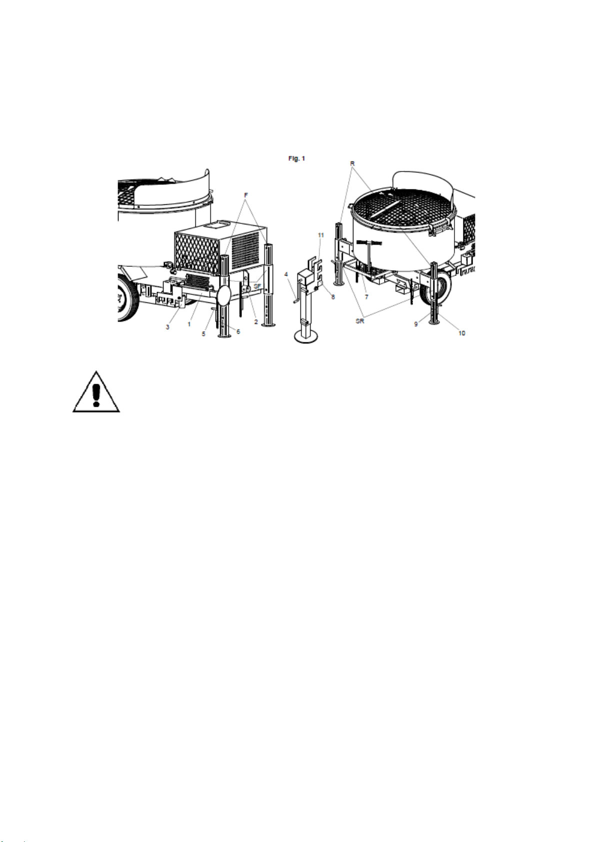
LIFTING THE MACHINE TO THE
MAXIMUMUNLOADING HEIGHT
CAUTION : Make sure the lift jack is on a solid flat surface
before beginning to raise the machine. Additionally, NEVER
work on or around the Mortarman® 750 MBP while the jack
stand is holding it up........Serious injury can result!
1) Extract the lifting foot [1] (fig. 1) from the lateral housing.
2) Position the lifting foot in front of the drive hole [2] located on the engine side of the machine (front), and lower
the foot [1] until pin [3] is aligned with hole [2], by means of the handwheel [4].
3) Insert pin [3] in the drive hole [2] and turn handwheel [4] to raise the machine until the front legs [F] are
detached from the ground.
4) Remove locking pins [5] of legs [F], removing the relative cotter pins [6], to lower the legs to the ground.
5) Turn handwheel [4] again to raise the machine to the maximum height, ensuring that the hole on the leg
supports (SF) is aligned with the 4th hole (starting from the bottom) on each leg [F].
6) Insert locking pins [5] and secure in position by means of cotter pins [6].
7) Remove the lifting foot [1] and position it on the other side of the machine (rear), in the vicinity of the roll bar [7].
8) Lower the lifting foot [1] until the lower bracket [8] can be inserted below the roll bar [7] and centred.
9) Raise the machine by means of the handwheel [4], so that the rear legs [R] no longer touch the ground.
10) Remove locking pins [9] of legs [R], removing the relative cotter pins [10], to lower the legs to the ground.
11) Turn handwheel [4] again to raise the machine until the hole on the leg supports (SR) is aligned with the 4th
hole (starting from the bottom) on each leg [R].
12) Insert locking pins [9] and secure in position by means of cotter pins [10].
13) Remove the lifting foot [1] and use the handwheel [4] to lower the machine until the upper bracket [11] can
be inserted below the roll bar [7] and centred.
14) Raise the machine by means of the handwheel [4], so that the rear legs [R] no longer touch the ground.
15) Remove locking pins [9] of legs [R], removing the relative cotter pins [10], to lower the legs to the ground.
16) Turn handwheel [4] again to raise the machine until the hole on the leg supports (SR) is aligned with the 5th
hole (starting from the bottom) on each leg [R].
17) Insert locking pins [9] and secure in position by means of cotter pins [10].
18) Remove the lifting foot [1] and return to the lateral housing.

To lower the machine, proceed as follows:
1) Extract the lifting foot [1] (fig. 1) from the lateral housing.
2) Remove the lifting foot [1] and position it on the rear side of the machine, in the vicinity of the roll bar [7].
3) Raise the lifting foot [1] by means of the handwheel [4] until the upper bracket [11] can be inserted below the
roll bar [7] and centred.
4) Turn the handwheel [4] again so that the rear legs [R] no longer touch the ground.
5) Remove leg locking pins [10], removing the relative cotter pins [9], to lower the legs [R] to the ground.
6) Turn handwheel [4] again to lower the machine until the hole on the leg supports (SR) is aligned with the
4th hole (starting from the bottom) on each leg [R].
7) Insert locking pins [9] and secure in position by means of cotter pins [10].
8) Remove the lifting foot [1] and use the handwheel [4] to lower the machine until the lower bracket [8] can be
inserted below the roll bar [7] and centred.
9) Turn the handwheel [4] again so that the rear legs [R] no longer touch the ground.
10) Remove leg locking pins [9], removing the relative cotter pins [10], to lower the legs [R] to the ground.
11) Turn handwheel [4] again to lower the machine until the hole on the leg supports (SR) is aligned with the
3rd hole (starting from the bottom) on each leg [R].
12) Insert locking pins [9] and secure in position by means of cotter pins [10].
13) Remove the lifting foot [1] and position on the other side of the machine (front) in front of the drive hole [2]
and lower the foot [1] until pin [3] is aligned with hole [2], by means of the handwheel [4].
14) Insert pin [3] in the drive hole and turn handwheel [4] to raise the machine until the front legs [F] are
detached from the ground.
15) Remove locking pins [5] of legs [F], removing the relative cotter pins [6], to lower the legs to the ground.
16) Turn handwheel [4] again to lower the machine until the hole on the leg supports (SR) is aligned with the
3rd hole (starting from the bottom) on each leg [F].
17) Insert locking pins [5] and secure in position by means of cotter pins [6].
18) Remove the lifting foot [1] and return to the lateral housing.

IMPORTANT NOTESANDADVICE
Do's and Don'ts on the Safe Use of the Mortarman® 750
In the interest of safety, whoever uses or maintains the MORTARMAN® 750
should first read this manual and become familiar with all of the
important safety notes. Failure to follow this advice may result in
injury to yourself and others.
WHAT TO DO !
- Carefully read and understand these instructions before operating themixer.
- Always turn off the engine and disconnect the spark plug wire before cleaning or maintaining the mixer.
Mixes powered by electricmotors should be unplugged fromtheir power source before servicing is performed.
- Make sure the safety guards are always in place.
-When using themachine always wear safety boots with reinforced toe-caps, safety glasses, gloves, hard
hat, and clothing with the appropriate fit.
- Practice starting and stopping the machine.
- Keep the mixer clean and free or debris build-up.
- Periodically inspect your mixer for abnormal wear or damage.
- Always stop the engine before adding fuel.
-Whenever themixer begins to sound or run in an unusualmanner...... STOP THEMACHINE !.... and do
not re-start the mixer until the difficulty is understood and repaired.
--SILICA DUST WARNING
Grinding/cutting/drilling of masonry, concrete, metal and other materials with silica in their composition my
give off dut or mists cintainig crystalline silica. Silica is a basic component of sand, quartz, brick clay, granite
and numerous other minerals and rocks. Repeated and/or substantial inhalation of airborne crystalline silica
can cause serious or fatal respiratory diseases, including silicosis. In addition, California and some other
authorities have listed respirable crystallinesilica as a substance known to cause cancer. Whwn cutting such
materials, always follow respiratory precautions.
Use appropriate NIOSH-approved respiratory protection where dust hazard may occur. Paper masks or
surgical masks without a NIOSH approval number are not recommended because they do little to protect the
worker. For more information about respirator programs, including what respirators have received NIOSH
approval as safe and effective, please visit the NIOSH website at:
http://www.cdc.gov/niosh/topics/respirators
Observe OSHA regulations for respirator use (29 C:F.R. § 1910.134).
Visit http://www.osha.gov for more information.

California proposition 65 message
Some dust created by power sanding, sawing, grinding, drilling, and other construction activities contain
chemicals know (to the State of California) to cause cancer, birth defects or other reproductive harm. Some
examples of these chemicals are:
-Lead, from lead-based paints
-Crystalline silica, from bricks and cement and other masonry products
-Arsenic and chromium, from chemically treated lumber
For further information , consult the following sources:
http://www.osha.gov/dsg/topics/silicacrystalline/index.html
http://www.cdc.gov/niosh/docs/96-112/
http://oehha.ca.gov/prop65/law/P65law72003.html
http://www.dir.ca.gov/Title8/sub4.html
http://www.P65warnings.ca.gov
Your risk from these exposures varies depending on how often you do this typer of work. To reduce your
exposure to these chemicals, work in a well-ventilated area, and work with approved safety equipment, such
as dust masks that are specially designed to filter out microscopic particles. Where use of a dust extraction
device is possible, it should be used. To achieve a high level oof dust collection, use an industrial HEPA
vacuum cleaner. Observe OSHA 29 CFR part 1926.57 and 1926.103.

IMPORTANT NOTESANDADVICE
What NOT TO DO !
DONOT
- place your hands or any other object inside the mixer drum while it is running.
DONOT
- place any tools or other objects in or around the mixer drum while it is running.
DONOT
- operate the mixer on a surface that is UNEVEN.. .. if the MORTARMAN® 750 is placed on an incline, it
can fall over or roll away!
DONOT
- clean, assemble or work on themixer while it is plugged in, or while the spark plug wire is connected to the
spark plug!
DONOT
- operated the mixer in or around water puddles!
DONOT
- leave themixer unattended!
DONOT
- use the safety grate interlock switch for stopping the mixer......shut off the motor.....this safety interlock
system is designed to provide some protection for negligent operators. .....REMEMBER, never raise the
safety grate while the mixer is running, unplug the mixer from its power source, then the grate may be
raised properly.
DONOT
- allow other persons around the mixer while it is operating.
DONOT
- operate the MORTARMAN® 750 if you are uncertain as to how to run the machine.... Contact your local
IMER DISTRIBUTOR or call IMER U.S.A. at (800) 275-5463.
-SILICA DUST WARNING
NOTE: These safety instructions are simple and straight forward.....FOLLOW THEM!
WEWANT SAFEAND EFFICIENT
PRODUCTION/OPERATION
FORALL OUR CUSTOMERS!

OPERATING INSTRUCTIONS
1. Before starting the engine read the Honda manual provided and become familiar with the GXV 390
powerplant.
2. Place the MORTARMAN® 750 at the appropriate working height. The working height is determined by
which type of container the material mixed is to be discharged into:
For Example : Wheelbarrow, Mud Bucket, Mud Pan
For raising and lowering theMORTARMAN® 750, see the previous section on the set-up procedure.
3. Connect the water supply hose to the Chicago fitting provided. Practice operating the water control
lever......one direction discharges water into the drum......the other direction sends water into the clean up
hose.
*IMPORTANT NOTE* Before adding material to the mixing drum make certain no foreign
objects are in the drum, and that the discharge gate is in the closed position.
4. Now start the mixer, the mixing paddles should move smoothly as they pass around the drum, if their
action is irregular and noisy, stop the mixer.....contact your local IMER Distributor or call IMER U.S.A.
direct of (800) 275-5463.
*IMPORTANT NOTE*Machines equipped with combustion engines and key ignitionmust
be started as follows: rotate the key clockwise, fromposition 0 to the next click (position
1) and keep turned to start the engine. If themachine does not start, attempt the start-up
procedure again without insisting for more than 5 seconds at a time. Once the engine is
started, leave the key in position 1, to enable the starter battery to recharge.
5. With the mixer running at full power, add the cement and sand into drum dry....the MORTARMAN® has
the ability to spin andmix a full load dry. This is a great feature , as it allowsmaterial to throughly blend and
mix before water is added.
*IMPORTANT NOTE* The Mortarman® 750 is much different from a concrete mixer and
cannot be used to mixmaterial with aggregate (rocks). This is because the Mortarman®
750 has paddles which are driven through the material with huge amounts of
torque.....should a paddlewedge a rock between itself and the drum, substantial damage
will result.
If thematerial beingmixed is not bagged pre-mix or discharged froma silo system, then
make certain there are no rocks in it.
Be especially cautious if sand is delivered by truck from a sand and gravel supply yard.
Let them know when you order, that no rocks or pebbles of any type are allowed in your
sand.
Some light aggregates, such as terrazzo piecesmay be run in themixer, however, contact
IMER U.S.A. or your local dealer for the proper set-up techniques.
6. Fill the mixer to the top of the free spinning agitation trident paddle.....filling the mixer above this point
will not provide sufficentmixing action for the loadedmaterial.
REMEMBER: theMORTARMAN® 750mixes incredibly fast......there is no need to over loadit.
7. Now that thematerial has mixed a fewseconds dry, the water can be added until the desired consistency
has been achieved.
8. Once the material is mixed to the consistency desired, position the appropriate container beneath the
discharge chute area and then slide the discharge gate open.
9. If the mixer is stopped while material is still in the drum, do not allow the material to harden up. It is
possible to re-start the mixer with up to 3/4 of a load in the drum. If the drum was at full capacity when the
mixer stopped, discharge some material, then re-start the machine.

MAINTENANCE
The MORTARMAN® 750 is designed to require very low maintenance, however, following the few basic
maintenance procedures listed below will greatly reduce your machine's down time.
1. Clean themixer throughly after each use and do not allowmaterial to build up on any portion of themixer.
REMEMBER - Always unplug the mixer, or disconnect the spark plug wire before
performing any maintenance procedures.
2. Change the gearbox oil after the first 50 hours of operation, after that the oil should be changed every 250
hours. Changing the oil is a simple procedure, as the drain bolt and a sight window for the full levelmarking
are located on the gearbox body. Use a premium SAE 90 gearbox oil when making the change.
3. Check the drive belt tightness when the machine arrives from our factory.....maintain the belts at this
tension......taunt, yet not extremely tight. Caution, if the belts are overly tightened, damage can result to
themotor and the gearbox.
REMEMBER: drive belts experience themajority of strech during the first 15 hours of operation,monitor the
belts closely during break-in.
NOTE : NEVER touch or adjust the belts while the machine is operating
To tighten the belts the motor is moved forward, further away from the rear pulley. Make sure the two
adjusting bolts are tightened in equal amounts, as the motor's drive pulleymust stay in alignment
with the gearbox pulley. Should the belts continually come off the pulley, check the following:
- condition of the belts, are they worn out, are they the proper specification
- alignment of the drive pulley and gearbox pulley, are they in line
- are the pulleys themselves in good condition? ......not bent or clogged with debris.
NOTE : it is not advisable to replace just one belt,they need to be replaced in sets. This
is because a new belt needs a different degree of tightness than a used belt. It is always
a good idea to have a spare set of belts in your truck......replacement is straight forward
and simple.....be smart and be prepared!
4. The paddle assembly hardware should bemonitored and retightened the first 15 hours of operation.
After the components have seated in, it is still a good idea to check the paddle hardware on a weekly basis,
or whenever themachine is thoroughly cleaned.
Many contractors have found it very effective to have an additional set of paddles....when one set becomes
ready formaintenance, remove the entire paddle spider and drop on the spare.
This procedure takes less than one hour and allows the used set of paddles to be set aside andmaintained
at your leisure.
As the paddle wiper rubber wears it is important to bring the distance between the wiper rubber, and the
drum back to its original specification.......which is 5mm or 1/5".
DO NOT place the rubber flush against the drum....... this will cause the paddle to drag excessively and
can lead to the paddle bending or breaking.
NOTE : Should the paddles ever begin to emit sharp scraping sounds, or the paddle spider system begin to
vibrate heavily, stop the mixer. Disconnect all power and unload by hand if necessary. Do not restart the
machine until the cause of the malfunction has been ascertained.
BATTERY:
- Keep the battery clean and dry.
- Use a moist anti-static cloth only to wipe the battery, otherwise there is a danger of explosion.
- Do not open the battery.
- Recharge in case of insufficient starting power.

5. The area underneath the discharge gate will need to be hosed off a few times a day. The discharge gate
mechanism is equipped with a wiper which continually sweeps debris off the safety grate, however, a shot
of water every now and then will ensure smooth discharge.
REMEMBER .....do not remover the discharge safety grate under any
circumstances.....keep this area clean and material discharge will be no problem...it is
not worth lost fingers and hands to remove the safety grate!
6. Do not disconnect the safety interlock system on the mixer drum safety grate. Should it begin to
malfunction see your IMER Distributor immediately, or call IMER U.S.A. direct at (800) 275-5463.
7. Regarding motor maintenance, please review the manufacturer's manual which is supplied with each
machine.
IT IS IMPORTANT that the mixer power plant run properly, or the material mixing action may not be
thorough enough. The motor is the heart of this machine........take care of it!
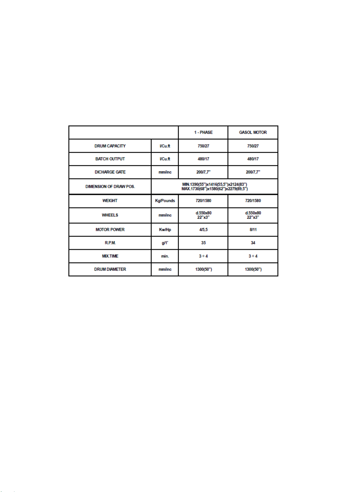
TECHNICAL SPECIFICATION
MORTARMAN® 750 MORTARMIXER
Due to Imer U.S.A. 's commitment to
Reasearch and Development,
specifications are subject to change
without notice.


SPARE PARTS LIST
MORTARMAN® 750 MORTARMIXER


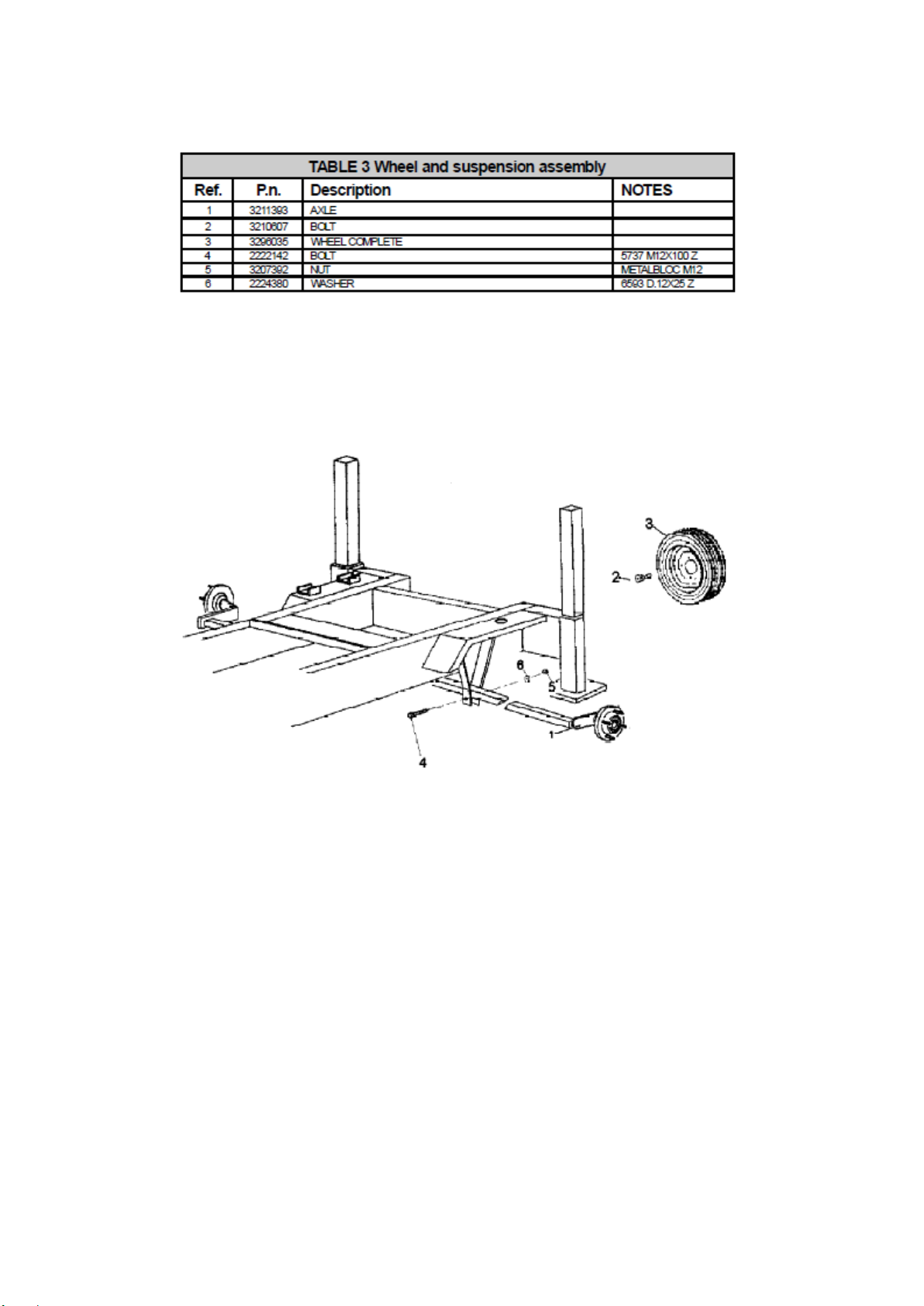
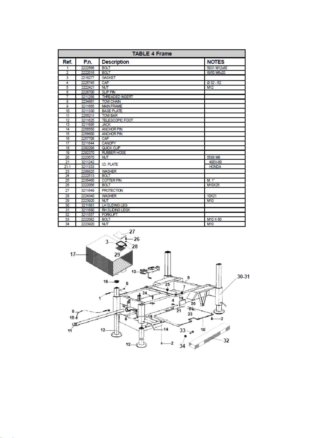
Table of contents
Other IMER Mixer manuals


