Ksenia KSI1000016.300 User manual

KSI1000016.300 - KSI1100016.300 - KSI1000048.300 - KSI1100048.300 - KSI1100128.300
Guida rapida
Quick Reference Guide
Guide d’installation rapide
Centrali integrate serie lares
lares Integrated Control Panel
Centrale intégrée serie lares
CODICE INST LL TORE DI F BBRIC : 123456
CODICE UTENTE DI F BBRIC : 147258
F CTORY DEF ULT INST LLER CODE: 123456
F CTORY DEF ULT END-USER CODE: 147258
CODE INST LL TEUR P R DEF UT: 123456
CODE UTILIS TEUR P R DEF UT: 147258
Ed. 01-2012
www.kseniasecurity.com

IT LI NO
INTRODUZIONE:.............................................................................................................................................................3
DESCRIZIONE DELLA PROGRAMMAZIONE DI FABBRICA:...............................................................................................3
SCHEMA DEI COLLEGAMENTI:.......................................................................................................................................6
COME ATTIVARE IL VOSTRO SISTEMA............................................................................................................................8
COME UTILIZZARE L IMPIANTO....................................................................................................................................10
ENGLISH
INTRODUCTION:..........................................................................................................................................................12
DEFAULT PROGRAMMING DESCRIPTION:....................................................................................................................12
CONNECTION DIAGRAM:.............................................................................................................................................15
HOW TO ACTIVATE YOUR SYSTEM...............................................................................................................................17
HOW TO USE YOUR SYSTEM........................................................................................................................................19
FR NÇ IS
INTRODUCTION:..........................................................................................................................................................21
DESCRIPTION DE LA PROGRAMMATION PAR DEFAUT:................................................................................................21
SCHEMA DE RACCORDEMENT:....................................................................................................................................24
COMMENT ACTIVER VOTRE SYSTEME?........................................................................................................................26
COMMENT UTILISER VOTRE SYSTEME?.......................................................................................................................28
Codice manuale: RMX0300005.400
2

ITALIANO
INTRODUZIONE:
La centrale lares che hai acquistato dispone di una programmazione di fabbrica che consente una rapida
installazione, senza bisogno di utilizzare il software basis, ma semplicemente modificando i parametri da
tastiera.
Nei paragrafi che seguono sono descritti la configurazione di fabbrica ed i passi da eseguire per la corretta
installazione della centrale.
DESCRIZIONE DELL PROGR MM ZIONE DI F BBRIC :
Partizioni:
Le partizioni (o aree) sono un raggruppamento logico di zone, che possono essere inserite o disinserite. A
seconda del modello di centrale possono essere programmate fino a 20 partizioni, nel caso della
programmazione di fabbrica ne sono definite due:
1. Sensori perimetrali , destinati a persiane, finestre, porte e sensori esterni all edificio.
2. Sensori volumetrici , destinati a sensori all interno dell abitazione.
Inserimenti:
Gli inserimenti sono programmi utilizzati per inserire/disinserire le partizioni. A seconda del modello di
centrale possono essere definiti fino a 64 diverse modalità di inserimento, nel caso della programmazione
di fabbrica ne sono definite tre:
1. Disinserito : entrambe le partizioni sono disinserite.
2. Inserito : entrambe le partizioni sono inserite con tempi di ingresso ed uscita attivi (modalità
'totale' o ‘sto uscendo di casa ).
3. Parziale : è inserita la sola partizione 'Sensori perimetrali'. Questa modalità può essere usata
quando una o più persone sono in casa, ad esempio durante la notte.
Zone:
Le zone sono gli ingressi di centrale, a cui possono essere collegati i diversi sensori. A seconda del modello
di centrale possono essere gestite fino a 128 zone, collegate sulla scheda madre della centrale lares, sulle
tastiere ergo (fino a 2 zone per tastiera) o sui moduli di espansione auxi (fino a 5 zone ognuno). Nel caso
della programmazione di fabbrica ne sono definite 10:
1. Zona 1 . Deve essere collegata sul morsetto 'i1' della centrale lares. È programmata ritardata in
ingresso ed in uscita, normalmente chiusa, appartenente alla partizione 'sensori perimetrali'. È
pensata per essere utilizzata per il contatto magnetico dell'ingresso principale.
2. Zone da 2 a 6 . Devono essere collegata dal morsetto 'i2' al morsetto 'i6' della centrale lares. Sono
tutte programmate senza ritardi, normalmente chiuse, appartenenti alla partizione 'sensori
3

ITALIANO
perimetrali'. Sono pensate per essere utilizzate sui contatti delle finestre o persiane.
3. Zone da 7 a 10 . Devono essere collegate dal morsetto 'M1' al morsetto 'M4' della centrale lares.
Sono tutte programmate senza ritardi, doppio bilanciamento, appartenenti alla partizione 'sensori
volumetrici'. Sono pensate per essere utilizzate sui sensori volumetrici installati all'interno
dell'abitazione.
Uscite:
A seconda del modello di centrale possono essere gestite complessivamente fino a 128 uscite, collegate
sulla scheda madre della centrale lares, sulle tastiere ergo (fino a 2 uscite per tastiera) o sui moduli di
espansione auxi (fino a 5 uscite ognuno), queste sono delle uscite fisiche, di tipo open collector. Ci sono
poi le uscite logiche, che devono essere utilizzate per attivare le segnalazioni sulle sirene su bus (imago e
radius). Nel caso della programmazione di fabbrica sono definite 5 uscite:
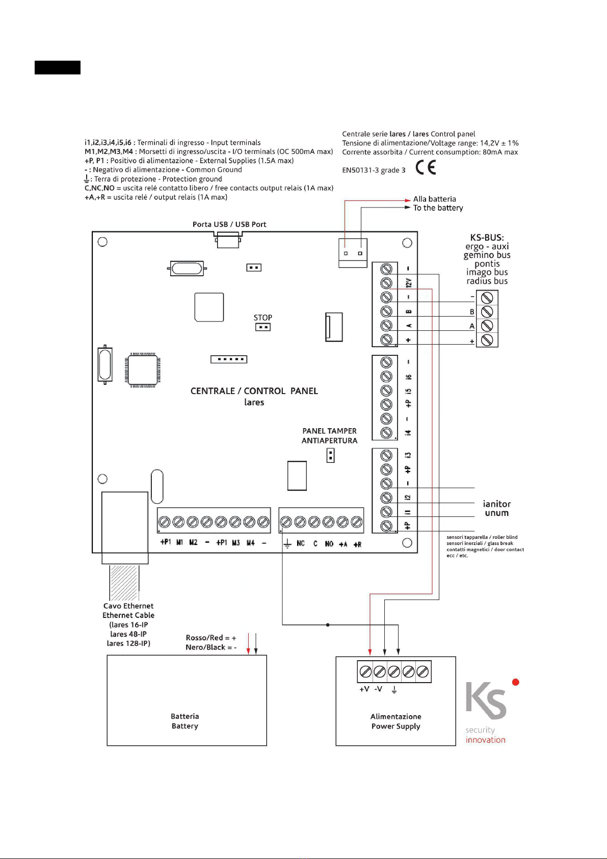
1. Relè . È l'unica uscita relè presente sul sistema, i cui morsetti sono accessibili sulla scheda madre
della centrale lares. Presenta uno scambio libero (C-NC-NO) ed uno collegato direttamente alla
+12 (+R, +A). Si attiva quando si verifica una condizione di allarme o di sabotaggio. Può essere
utilizzata per collegare sirene di tipo universale, o per attivare comunicatori esterni.
2. Stato impianto . è una uscita logica, che attiva i LED rossi lampeggianti sulla sirena da esterno
imago quando l'impianto è inserito.
3. Allarme imago : è una uscita logica, che attiva la sirena da esterno imago quando si verifica una
condizione di allarme o sabotaggio.
4. Allarme radius : è una uscita logica, che attiva la sirena da interno radius quando si verifica una
condizione di allarme o sabotaggio e l'impianto è inserito in modalità totale.
5. Uscita manuale : è una uscita fisica, associata al morsetto M1 della tastiera ergo. Si attiva/disattiva
quando si tiene premuto per 3 secondi il tasto 9 sulla tastiera ergo. E pensata per l attivazione di
un carico esterno (apriporta, apri-cancello, luci, …).
Periferiche BUS
Nella centrale possono essere messe in configurazione diverse periferiche, che variano a seconda del
modello di centrale. Nel caso della programmazione di fabbrica sono previste le seguenti periferiche:
1. Una tastiera LCD ergo (codice Ksenia KSI2100000.300)
2. Un lettore di prossimità volo (codice Ksenia KSI2200000.300 colore nero o KSI2200000.310 colore
bianco)
3. Una sirena da interno radius con funzione luce di emergenza (codice Ksenia KSI6101000.300)
4. Una sirena da esterno imago (codice Ksenia KSI6301000.xxx con diverse varianti di colore)
4

ITALIANO
Codici
A seconda del modello di centrale possono essere attivati fino a 128 codici utente, nel caso della
programmazione di fabbrica ne sono definiti 5:
1. un codice utente principale , PIN di default 147258
2. quattro codici utente , con PIN di default (000003, 000004, 000005, 000006) che devono però
essere attivati dal codice utente o da quello installatore.
Chiavi (Mini-Tags):
A seconda del modello di centrale possono essere attivati fino a 128 chiavi, nel caso della
programmazione di fabbrica ne sono definite 5, che devono essere acquisite dal menu installatore.
Avvisatore voca e, SMS e WebServer gratuito
Qualora si vogliano utilizzare le funzionalità di avvisatore vocale e/o SMS è necessario collegare alla
centrale il comunicatore gemino BUS. Ino tre per uti izzare a pieno tutte a potenza de sistema e quindi
permettere a ’utente fina e performance straordinarie qua i a gestione da remoto tramite web-server
e mappe grafiche è necessario acquistare uno dei mode i di centra e che integrano a bordo a
connettività IP, codici Ksenia: KSI1100016.300 - KSI1100048.300 - KSI1100128.300.
Anche in questo caso esiste una programmazione di fabbrica, scaricabile direttamente dal nostro sito
internet, accedere alla 'AREA RISERVATA' agli installatori, 'SOFTWARE', 'PROGRAMMAZIONE DI DEFAULT'.
Basta scaricare il file di programmazione (default_ITA.zip), decomprimerlo e salvarlo su una chiave USB,
collegare la chiave USB con l'apposito adattatore (codice Ksenia KSI7501000.020) alla centrale. Inserire il
codice installatore da tastiera (123456) scorrere il menu fino alla voce 'Programmazione da USB', premere
il tasto enter. La fase di caricamento dei dati dura alcuni minuti, al termine del quale la centrale ha
caricato i messaggi vocali, il webserver e gli SMS.
La centrale è programmata per inviare le segnalazioni di allarme ai primi due numeri della rubrica, e gli
SMS ad i numeri 3 e 4. Sarà sufficiente inserire il numero telefonico per abilitare o meno l'invio della
segnalazione.
5

ITALIANO
SCHEM DEI COLLEG MENTI:
6

ITALIANO
In figura è illustrato uno schema di collegamento di principio. Tutte le periferiche BUS Ksenia (tastiera
ergo, comunicatore gemino BUS, sirene da esterno ed interno, etc...) dispongono di 4 morsetti
(identificati con +,A,B,-) che devono essere collegati tra loro in parallelo con gli omonimi morsetti presenti
in centrale. I sensori devono essere collegati sui morsetti di ingresso (ix o Mx), con riferimento su
negativo. Nel caso di collegamento con configurazione doppio bilanciamento lo schema di collegamento è
il seguente:
Dove T è il contatto di sabotaggio presente sul sensore, ed A il relè di allarme. R1 ed R2 sono due
resistenze di valore 10KOhm, fornite in dotazione con la centrale ed i moduli di espansione auxi.
7

ITALIANO
COME TTIV RE IL VOSTRO SISTEM
In questa sezione sono descritti i soli passaggi necessari per attivare il vostro sistema. Per la
programmazione completa (da tastiera o da software basis) fare riferimento al manuale di
programmazione.
cquisizione delle periferiche sul BUS
Una volta terminati i collegamenti, la centrale acquisisce le periferiche su BUS, ma queste devono essere
assegnate al sistema. In questa condizione (periferica funzionante ma non assegnata) il display della
tastiera non riporta alcuna indicazione.
Per assegnare le periferiche presenti sul BUS al sistema procedere come segue:
1. Inserire in codice installatore su tastiera ergo (123456)
2. Dal menu, scorrere fino alla voce 'Programmazione' e premere il tasto 'Enter'
3. Scorrere il menu fino alla voce 'Periferiche BU ' e sfiorare il tasto 'Enter'
4. Scorrere il menu fino alla voce 'Assegna' e sfiorare il tasto 'Enter'
5. Viene mostrata la prima periferica trovata, con il relativo numero di serie, sfiorare due volte il
tasto 'Enter' per assegnare la periferica al sistema.
6. Ripetere la programmazione dal punto 4, fino a che tutte le periferiche non siano state assegnate.
(compare sul display la scritta 'Nessuna periferica da assegnare!'.
7. Una volta completato il ciclo di assegnazione, uscire dalla programmazione premendo il tasto 'E C'
fino all'uscita della programmazione.
Modifica della tipologia di bilanciamento delle zone
Se si vuole modificare il bilanciamento di una zona procedere come segue:
1. Inserire in codice installatore su tastiera ergo (123456)
2. Dal menu, scorrere fino alla voce 'Programmazione' e sfiorare il tasto 'Enter'
3. Scorrere il menu fino alla voce 'Zone' e sfiorare il tasto 'Enter'
4. Scorrere la lista delle zone fino a trovare quella desiderata e sfiorare il tasto 'Enter'
5. Scorrere il menu fino alla voce 'Bilanciamento' e sfiorare il tasto 'Enter'
6. Selezionare il tipo di Bilanciamento desiderato tra quello proposto e sfiorare il tasto 'Enter'
7. Una volta completato il ciclo di programmazione, uscire premendo più volte il tasto 'E C'.
ttivazione dei codici e modifica dei PIN
Per attivare altri codici utente (oltre a quello attivato di default, con PIN 147258) procedere come segue:
1. Inserire il codice installatore su tastiera ergo (123456)
8

ITALIANO
2. Dal menu, scorrere fino alla voce 'Programmazione' e sfiorare il tasto 'Enter'
3. Scorrere il menu fino alla voce 'Gestione Codici' e sfiorare il tasto 'Enter'
4. Scorrere la lista dei codici fino a trovare il codice da modificare e sfiorare il tasto 'Enter'
5. Scorrere gli attributi del codice e sfiorare il tasto 'Enter' per modificarlo. Ad esempio per attivare il
codice, selezionare la voce 'Abilitazione' ed impostarla su ON.
6. Per modificare il PIN selezionare la voce 'Modifica PIN' ed inserire il nuovo PIN.
7. Per modificare altri codici ripetere le operazioni dal punto 4
8. Una volta completato il ciclo di programmazione, uscire premendo più volte il tasto 'E C'.
cquisizione chiavi di prossimità
Per acquisire delle chiavi di prossimità procedere come segue:
1. Inserire in codice installatore su tastiera ergo (123456)
2. Dal menu, scorrere fino alla voce 'Programmazione' e sfiorare il tasto 'Enter'
3. Scorrere il menu fino alla voce 'Gestione Chiavi' e sfiorare il tasto 'Enter'
4. Scorrere il menu fino alla voce ' alva Chiavi' e sfiorare due volte il tasto 'Enter'
5. Avvicinare la chiave alla tastiera
6. Per acquisire ulteriori chiavi ripetere la procedura dal punto 4.
7. Una volta completato il ciclo di programmazione, uscire premendo più volte il tasto 'E C'.
Modifica/ Inserimento dei numeri in rubrica
Per aggiungere modificare un numero in rubrica procedere come segue:
1. Inserire in codice utente principale su tastiera ergo (147258)
2. Entrare nel menù di gestione premendo il tasto #
3. Dal menu, scorrere fino alla voce 'Menu Avanzato' e sfiorare il tasto 'Enter'
4. Dal menu, scorrere fino alla voce 'Rubrica' e sfiorare il tasto 'Enter'
5. Scorrere la lista dei numeri presenti, sfiorare il tasto 'Enter' per modificare
6. sfiorare 'Enter' per modificare la descrizione, o scorrere fino alla voce 'Numero' per modificare il
numero
7. sfiorare il tasto 'Enter' per modificare il numero
8. Inserire il numero dalla tastiera, e sfiorare 'Enter' al termine della programmazione.
9. Uscire dal menu premendo più volte il tasto 'E C'
9

ITALIANO
COME UTILIZZ RE L’IMPI NTO
Inserimento
Per inserire l impianto si può procedere in uno dei seguenti modi:
•Inserire il codice utente su tastiera ergo e digitare la cifra 1
•Inserire il codice utente su tastiera ergo, ruotare lo scroll fino alla visualizzazione della parola
‘Inserimento e sfiorare il tasto Enter.
•Avvicinare la chiave alla tastiera ergo e ripetere una delle sequenze sopra descritte.
•Avvicinare la chiave al lettore volo ed attendere il colore rosso; quindi allontanare la chiave.
Disinserimento
Per disinserire l impianto si può procedere in uno dei seguenti modi:
•Inserire il codice utente su tastiera ergo e digitare la cifra 0
•Inserire il codice utente su tastiera ergo, ruotare lo scroll fino alla visualizzazione della parola
‘Disinserimento e sfiorare il tasto Enter.
•Avvicinare la chiave alla tastiera ergo e ripetere una delle sequenze sopra descritte.
•Avvicinare la chiave al lettore volo ed attendere il colore verde; quindi allontanare la chiave.
Modo Notte
Per inserire l impianto in modo notte si può procedere in uno dei seguenti modi:
•Inserire il codice utente su tastiera ergo e digitare la cifra 2
•Inserire il codice utente su tastiera ergo, ruotare lo scroll fino alla visualizzazione della parola ‘Modo
Notte e sfiorare il tasto ‘Enter .
•Avvicinare la chiave alla tastiera ergo e ripetere una delle sequenze sopra descritte.
•Avvicinare la chiave al lettore volo ed attendere il colore blu; quindi allontanare la chiave.
ttivazione uscita
Per attivare l uscita si può procedere nel seguente modo:
•Sulla tastiera ergo tenere premuto il tasto 9 per 3 secondi.
Webserver (fare riferimento al manuale di programmazione per maggiori dettagli):
Installando un modello di centrale IP, tutti gli utenti sono abilitati a gestire da remoto l'impianto da remoto
attraverso il webserver dove tutte le impostazioni di sopra descritte sono già presenti.
Per utilizzarlo basta aprire un browser internet ed inserire l'indirizzo http://lares_board dalla stessa rete dove la
centrale è collegata. Questo indirizzo è attivo solo se la rete è configurata con il DHCP. Se le impostazioni di rete
sono differenti, la centrale può essere facilmente configurata dal software basis, dove sono anche disponibili le
mappe grafiche con integrazione video. Per una demo, aprire il seguente link:
www.kseniasecurity.com/demos/webserver/it
10

ITALIANO
Con la presente, Ksenia ecurity dichiara che
laresTM
è conforme ai requisiti essenziali ed alle altre disposizioni pertinenti stabilite dalla normativa EN50131-1.
Le dichiarazioni di conformità complete si possono scaricare all’indirizzo: www.kseniasecurity.com
L’installazione di queste apparecchiature deve essere effettuata a regola d’arte, in accordo con le norme
vigenti. Queste apparecchiature sono state sviluppate secondo criteri di qualità, affidabilità e prestazioni
adottati dalla Ksenia ecurity. i raccomanda di verificare il corretto funzionamento del sistema almeno
una volta al mese. Le procedure per il collaudo dipendono dalla configurazione del sistema. Chiedere
all’installatore del sistema le procedure da seguire. Ksenia ecurity rl declina ogni responsabilità nel caso
in cui le apparecchiature vengano manomesse da personale non autorizzato. Il contenuto di questo
manuale può essere soggetto a modifiche senza preavviso e non rappresenta un impegno da parte della
K ENIA ECURITY.
CERTIFIC ZIONI
Paese Certificazioni Centrali antifurto serie aresTM
Europa CE
Europa EN50131-3 Grado 3
Il presente manuale è valido per tutti i modelli di centrale (salvo le eccezioni riportate nelle relative
sezioni). La revisione di centrale a cui fa riferimento questo manuale è 1.2 build xxx.
Direttiva Rifiuti di apparecchiature elettriche ed elettroniche (RAEE ‐ WEEE) Questo prodotto NON deve
essere smaltito insieme ai rifiuti domestici. Riciclare presso impianto adeguato.
11

ENGLISH
INTRODUCTION:
To allow you a quick installation, this lares Control Panel is available with a factory default programming
(template programming) with no need of a PC with the basis software, but simply using the system
Keypad.
Next paragraphs describe the Factory Configuration and the steps to be followed to install your panel in
the correct way.
DEF ULT PROGR MMING DESCRIPTION:
Partitions:
The Partitions (or Areas) are a logic group of zones which can be armed or disarmed. Depending on the
Control Panel Model, up to 20 Partitions can be programmed. In this template, 2 Partitions have been
already programmed as follows:
1. Perimetral Detectors , meant for curtains, windows, doors and any detectors outside the building.
2. Volumetric Detectors , meant for the detectors inside the building.
Arm Modes:
They are used to arm/disarm Partitions. Depending on the Control Panel Model, up to 64 different Arm
Modes can be defined. In this template, 3 Arm Modes have been already programmed as follows:
1. Disarmed: both Partitions are disarmed.
2. Away: both Partitions are armed with active entry –and exit times (mode “full armed ” or “away
armed”.
3. Stay : only the “Perimetral Detectors” is armed ( mode “partially armed”). This is the most used
when one or more persons are at home, typically at night time.
Zones:
The Zones are the Control Panel inputs, to be linked to the different detectors. Depending on the Control
Panel model, up to 128 Zones can be managed, linked to the lares Control Panel, the ergo Keypad (up to 2
Zones per Keypad) and the auxi expansion modules (up to 5 Zones each module). In this template 10
Zones have been already programmed as follows:
1. Zone 1 . It has to be connected to the terminal 'i1' of the CP. It is programmed as “delayed” both in
entry and exit mode, NC (Normally Closed) and belonging to the “Perimetral Detectors“ Partition.
It is meant to be utilized for the magnetic contact at the main entrance.
2. Zone from 2 to 6. They have to be connected to the terminals from 'i2' to 'i6' of the CP. They are all
programmed with no delay, NC and belonging to the Partition called “Perimetral Detectors” . They
12

ENGLISH
are meant to be utilized for windows and or curtain magnetic contacts.
3. Zone from 7 to 10 . They have to be connected from the terminal 'M1' to the 'M4' of the CP. They
are all programmed with no delay, double-balance and belonging to the Partition “Volumetric
Detectors”. They are meant to be utilized for Volumetric Sensors installed inside the building.
Outputs:
Depending on the Control Panel Model, up to 128 Outputs can be managed contemporarily, linked to the
lares Control Panel, the ergo Keypad (up to 2 Zones per Keypad) and the auxi expansion modules (up to 5
Zones) all these being physical outputs OC (Open Collector) type. Additionally there are logic Ouputs,
which need to be used to activate events on the Bus Sirens (imago and radius). In this template 5 Outputs
have been already programmed as follows:
1. Relay. It is the only relay Output present on the Panel, whose terminals are available directly on
the lares Control Panel. It has a free contact (C-NC-NO) and one linked directly to +12V (+R, +A). It
activates itself when an alarm condition or a masking event is occurring. It can be used to link
Sirens of “Universal type” or to activate external communication devices.
2. Arming Status . It is a logic Output which activates the flashing red LEDs on the Outdoor imago
Siren when the system is armed Stay or Away .
3. Alarm imago : it is a logic Output which activates the Outdoor imago Siren when a condition of
alarm or tamper are occurring.
4. Alarm radius : it is a logic Output which activates the Indoor radius Siren when a condition of alarm
or tamper are occurring and the System is Armed (AWAY).
5. Manual Exit : it is a physical Output, associated to the M1 Terminal of the Keypad ergo. It
activates / disactivates when the number 9 will be touched for more then 3 seconds on the
Keypad. It is meant to activate an external automation (automatic gate, door opening, garden
lights, etc.)
BUS Periphera s:
The Control Panel Architecture enables to configure many different Peripherals, whose number depends
from the CP model. In this template, 4 Peripherals have been already programmed as follows:
1. Nr. 1 ergo Keypad (Ksenia code KSI2100000.300)
2. Nr. 1 volo Outdoor Proximity Reader (Ksenia code KSI2200000.300Black or KSI2200000.310 in
White color)
3. Nr. 1 r adius BUS Indoor Siren with Emergency Light Function (Ksenia code KSI6101000.300)
4. Nr. 1 imago BUS Outdoor Siren (Ksenia code KSI6301000.xxx with various color availability)
13

ENGLISH
Codes:
Depending from the Control Panel Model, up to 128 User Codes can be activated. In this Template, 5
Codes have been already programmed as follows:
1. Nr. 1 MASTER CODE, default PIN: 147258
2. Nr. 4 USER CODES , default PINs : 000003, 000004, 000005, 000006 ( which have to be activated
either from the Master User Code or from the Installer Code).
Tags:
Depending from the Control Panel Model, up to 128 Tags can be activated. In this Template, 5 Tags have
been already programmed but need to be assigned from the Installer menu.
Voice Menu & Messages, SMS and WebServer (free y avai ab e with no icense cost):
To take advantage of the Voice Menu and/or the SMS communication, the Control Panel needs to be
linked to the gemino BUS Bi-Directional GSM/GPRS Communicator. Moreover, to take advantage from all
fantastic remote WebServer capabilities, it is necessary to adopt one of the Ksenia Control Panel
Models with integrates the IP Connectivity, Ksenia codes : KSI1100016.300 - KSI1100048.300 -
KSI1100128.300.
Even in this case, there is a Template Programming free downloadable from our web site in the RESERVED
INSTALLER AREA : FILES DOWNLOAD => SOFTWARE => DEFAULT PROGRAMMING.
It is enough to download the programming file (default_en.zip), unzip and save it on a USB Key, connect
the USB Key with the related Adapter (Ksenia code KSI7501000.020) to the Control Panel. From the
Keypad, insert the Installer Code (123456), scroll the menu till ‘Program from USB and touch ‘ENTER .
The upload may last a few minutes, at the end of them the CP has loaded all voice messages, SMS and
WebServer.
The Control Panel is pre-programmed to send alarm events to the first 2 numbers of the Phone-Book as
well as the SMSs to the numbers listed as 3 and 4. It will be enough to insert the phone numbers to
activate this important feature of larm Signalling.
14

ENGLISH
CONNECTION DI GR M:
15

ENGLISH
In this table a Wiring Scheme is illustrated. All BUS Peripherals Ksenia (ergo Keypad, gemino BUS
GSM/GPRS Communicator, Outdoor & Indoor Sirens, etc.) are equipped with 4 terminals (identified with
the symbols +,A,B,-) which need to be connected among them in parallel with the homonymous terminals
on the CP mother board. The Detectors have to be connected on the Input terminals (ix or Mx), with
reference to the negative. In the case of a Double-Balance configuration, for the connections please refer
to the following Schema:
whereby T is the tamper contact present on the Detector and A the Alarm Relay. R1 and R2 are the two
Resistances having value of 10KOhm each and delivered together with the CP Mother-Board and the
expansion module auxi.
16

ENGLISH
HOW TO CTIV TE YOUR SYSTEM
In this section are described all the necessary steps to activate your System in the Default programming
from your System Keypad:
Enrolling of the BUS-Peripherals:
Once call wiring is completed, the Control Panel enrolls all Bus-Peripherals automatically, nevertheless
they have to be assigned to the System. In this condition, (Peripherals functioning but not assigned), the
Keypad display does not show any indication.
To assign the Peripherals to the System, this procedure has to be followed on the ergo Keypad:
Steps:
1. Insert the default Installator Code (123456)
2. From the menu, scroll up to 'Programming' and touch 'Enter'
3. Scroll the menu up to 'BU Peripherals' and touch 'Enter'
4. Scroll the menu up to 'Assign' and then touch 'Enter'
5. Once the first found Peripheral will be shown (with the relevant serial number), touch 'Enter' two
times to assign it to your System.
6. Repeat the programming sequence from step 4 to step 5 until all Peripherals will be assigned. It
will appear on the LCD Disaplay 'No peripheral to be assigned!'.
7. Once the Assigning Cycle is completed, exit from the programming by touching 'E C' repetitively
Change the Zone Balance type:
If you wish to modify one zone balance, please proceed following these steps:
1. Insert the Installer Code on the ergo Keypad (123456)
2. From the Menu, scroll up to 'Programming' and then touch 'Enter'
3. Scroll the Menu up to 'Zone' and then touch 'Enter'
4. Scroll the list of zones until you find the one desired and then touch 'Enter'
5. Scroll the Menu up to 'Balance' and then touch 'Enter'
6. Select the type of Balance desired among the proposed and then touch 'Enter'
7. Once the Programming Cycle is completed, exit from the programming by touching 'E C'
repetitively.
Code ctivation and how to change PIN:
To activate other User Codes (in addition or in substitution to the default-one: PIN 147258) proceed as
follows:
1. Insert the default Installer Code (123456) on the ergo Keypad
17

ENGLISH
2. From the Menu, scroll up to 'Programming' and then touch 'Enter'
3. Scroll the Menu up to 'Manage Codes' and then touch 'Enter'
4. Scroll the code list up you will find the Code to be changed and then touch 'Enter'
5. Scroll the Code attributions and then touch 'Enter' to modify it. For example, to activate a Code,
select 'enable ' and set it up as ON.
6. To modify a PIN, select 'Change PIN' and insert a new PIN.
7. To modify other Codes, repeat the sequence from step 4)
8. Once the Programming Cycle is completed, exit from the programming by touching 'E C'
repetitively
Tags enrolling :
To enroll the proximity Tags (or Keys), please follow the following steps:
1. Insert the default Installer Code (123456) on the ergo Keypad
2. From the Menu, scroll up to 'Programming' and then touch 'Enter'
3. Scroll the Menu up to 'Manage Tags' and then touch 'Enter'
4. Scroll the Menu up to ' ave Tag' and then touch 'Enter' two times
5. Approach your Tag close the Keypad logo (Antenna area)
6. To acquire more Tags repeat the sequence from step 4.
7. Once the Enrolling Cycle is completed, exit from the programming by touching 'E C' repetitively
dd or modify Phone Numbers in the Phone-Book:
To add or modify a number in your Phone Book please proceed as follows:
1. Insert the default User Code (147258) on the ergo Keypad
2. Enter the ‘User Menu by touching the symbol ‘#
3. From the Menu, scroll up to 'Advanced Options' and then touch 'Enter'
4. From the Menu, scroll up to 'Phone Book' and the touch 'Enter'
5. Scroll the list of available numbers, touch 'Enter' to add or modify
6. Touch 'Enter' to add/modify a description or scroll to 'Number' to add/modify a number
7. Touch 'Enter' to modify a number
8. Insert the number using the Keypad and then touch 'Enter' when finished
9. Exit from the programming by touching 'E C' repetitively
N.B.: For the Complete Programming Tree (either from the Keypad or from the basis software) please do
always refer to the Programming Manual available on our website or inside the basis software.
18

ENGLISH
HOW TO USE YOUR SYSTEM
rm way:
To arm your System in Away Mode you can proceed using one of the following methods:
1. Insert the user code on the ergo Keypad and touch the number ’1’
2. Insert the user code on the ergo Keypad, scroll up to ‘Arm Away and touch ‘Enter .
3. Approach your Tag to the ergo Keypad and then repeat one of the two above sequences.
4. Approach your Tag to the volo Outdoor Reader and wait the red color to appear then remove the
Tag.
Disarm:
To disarm your System you can proceed using one of the following methods:
1. Insert the user code on the ergo Keypad and touch the number ‘0’
2. Insert the user code on the ergo Keypad, scroll up to ‘Disarm and touch ‘Enter .
3. Approach your Tag to the ergo Keypad and then repeat one of the two above sequences.
4. Approach your Tag to the volo Outdoor Reader, wait until the green color to appear then
remove the Tag.
rm Stay:
To arm the Arm Stay Mode (Night Mode) you can proceed using one of the following methods.
1. Insert the User Code on the ergo Keypad and touch the number ‘2’
2. Insert the User Code on the ergo Keypad and scroll up to ‘Arm tay’ and then touch ‘Enter’
3. Approach your Tag to the ergo Keypad and then repeat one of the two above sequences.
4. Approach your Tag to the volo Outdoor Reader, wait until the blue color to appear then
remove the Tag.
Output ctivation:
To activate the default programmed Output you can proceed using the following method:
1. touch the number ‘9’ for 3 seconds
Webserver (please also refer to the Programming Manual):
Installing a lares-IP model, all users are enabled to use the Panel remotely through the WebServer
application where all the above pre-programming will be available by default.
To take advantage of it, the user has to open an internet browser and type the address
http://lares_board from the same network where the Panel is connected. This link works only if the
network supports DHCP. If different network settings are used, the Panel can be easily programmed from
the basis software, where also “floor-plans” incl. Video Surveillance Capability can be configured.
For a demo, have a ook at the fo owing ink: www.kseniasecurity.com/demos/webserver/en
19

ENGLISH
Hereby Ksenia ecurity state that
aresTM
complies with the essential requirements and other pertinent provisions as set forth by the EN50131-1
standards.
The complete statements of compliance can be downloaded from www.kseniasecurity.com
These pieces of equipment must be installed to standard, in accordance with the applicable regulations.
They were developed under criteria of quality, reliability and performance as established by Ksenia
ecurity. We recommend that you check the correct operation of the system at least once a month. The
test procedures depend on the system configuration. Please ask the system installer what procedures
should be followed. Ksenia ecurity srl waive any and all liability should the equipment be tampered with
by unauthorized personnel. The contents of this manual may be subject to change without prior notice and
the manual itself does not legal bind K ENIA ECURITY.
CERTIFICATIONS
Country Certifications aresTM series Burglar Alarm Systems
Europe EC
Europe EN50131-3 Grade 3
This manual is valid for all the models of lares control panel (all the exceptions are reported in the
relative sections). The FW revision of lares which this document refers to is 1.2 build XXX.
Garbage directive for electric and electronic devices (RAEE ‐ WEE) This product CAN T be disposed with
household garbages Recycle at recicling plant.
20
This manual suits for next models
4
Table of contents
Languages:
Other Ksenia Control Panel manuals