Ksenukai FXAM1H-ZP2-1-250E User manual

FXAM1H-ZP2-1-250E
Instruction manual (Original instructions) GB pg 11-23
Käyttöohje (Alkuperäisten ohjeiden käännös) FI pg 24-36
Bruksanvisning (Översättning av originalinstruktionerna) SE pg 37-49
Bruksanvisning (Oversettelse av de opprinnelige instruksjonene) NO pg 50-62
Руководство пользователя (Перевод исходных инструкций) RU pg 63-77
Kasutusjuhend (Tõlgitud originaal juhendist) EE pg 78-90
Instrukcijas (Tulkojums no oriģinālvalodas) LV pg 91-103
Instaliavimo instrukcijos (Vertimas originali instrukcija) LT pg 104-116
Instrukcja obsługi (oryginalna instrukcja) PL pg 117-131

2
(1)
K
G
B ED
I
L
M
N
OP
Q
F
A C
H
J
3 6 10 114 9 1252
1
(2)
7 8 13 14 15 16

3
(3)
24 23 22 20
25
17 18
19
27 28
21
30
26
29
31
(4) (5)
(6) (7)
23
31
3,4 & 5
3,4 & 5 31
23
20
3,4 & 5
3,4 & 5
17
25
10 & 12
10 & 12
20
31
23
17
25

4
(8) (9)
(10) (11)
11
22
20
12
(12) (13)
(14) (15)
3,4 & 5 3,4 & 5
17 2331
20
13,14,15,16 & 29 20 22
1
17
1
20
1
23
20
17

5
(16) (17)
(18) (19)
(20)
(21) (22)
2
23
9
8
7
6

6
(23) (24)
(25) (26)
(27) (28)
(29) (30)
max. 3-5mm

7
(31) (32)
(33) (34)
(35) (36)
(37) (38)

8
(39) (40)
(41) (42)
(43) (44)
(45) (46)

9
(47) (48)
(49) (50)
(51) (52)
(53)

10
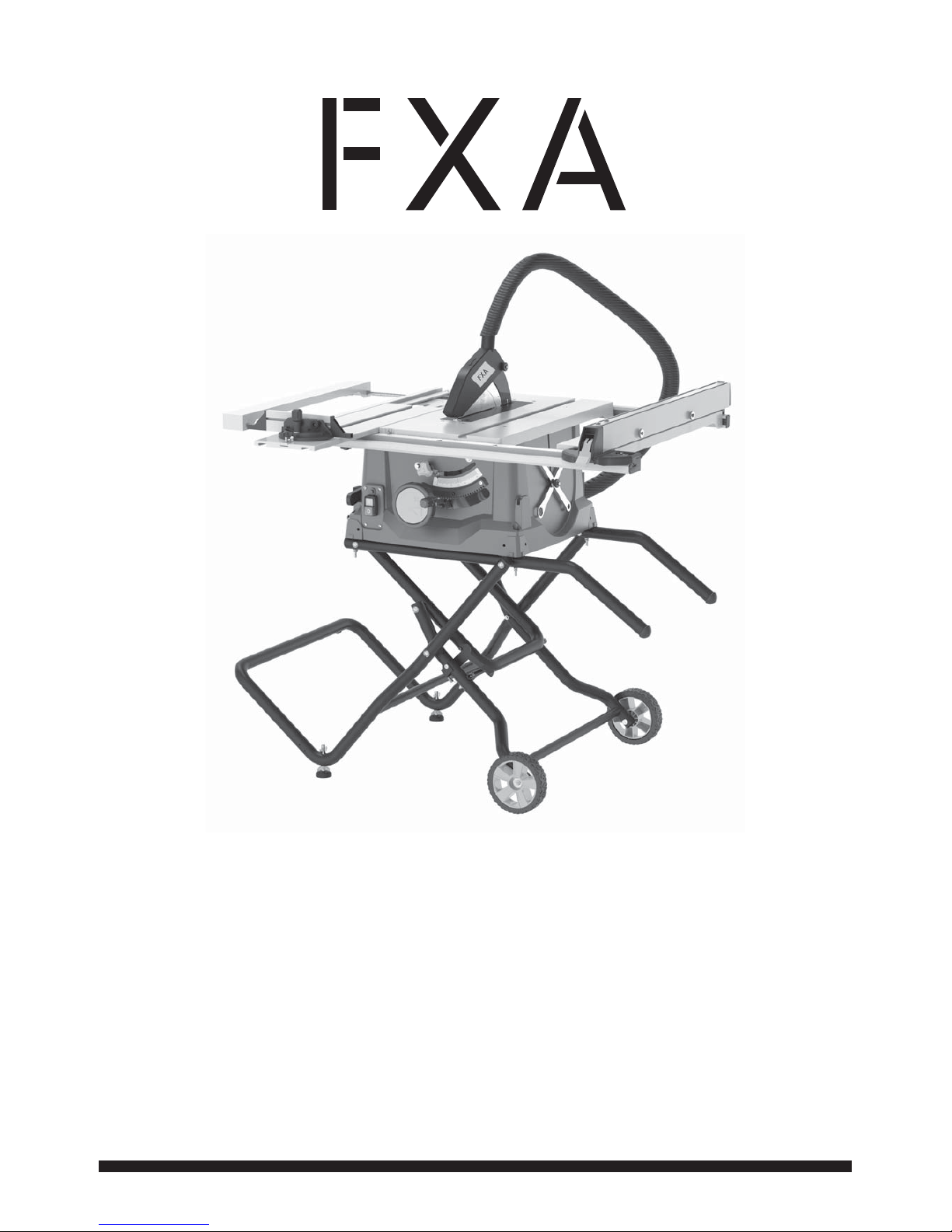
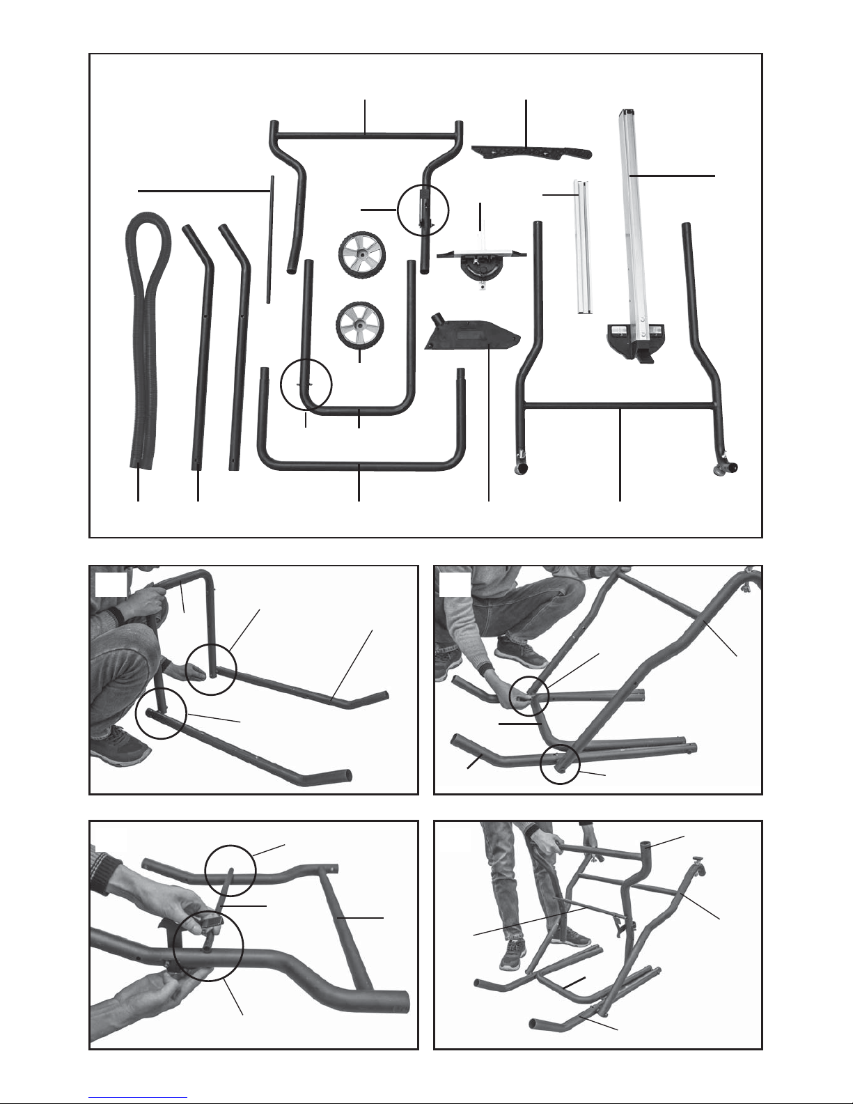
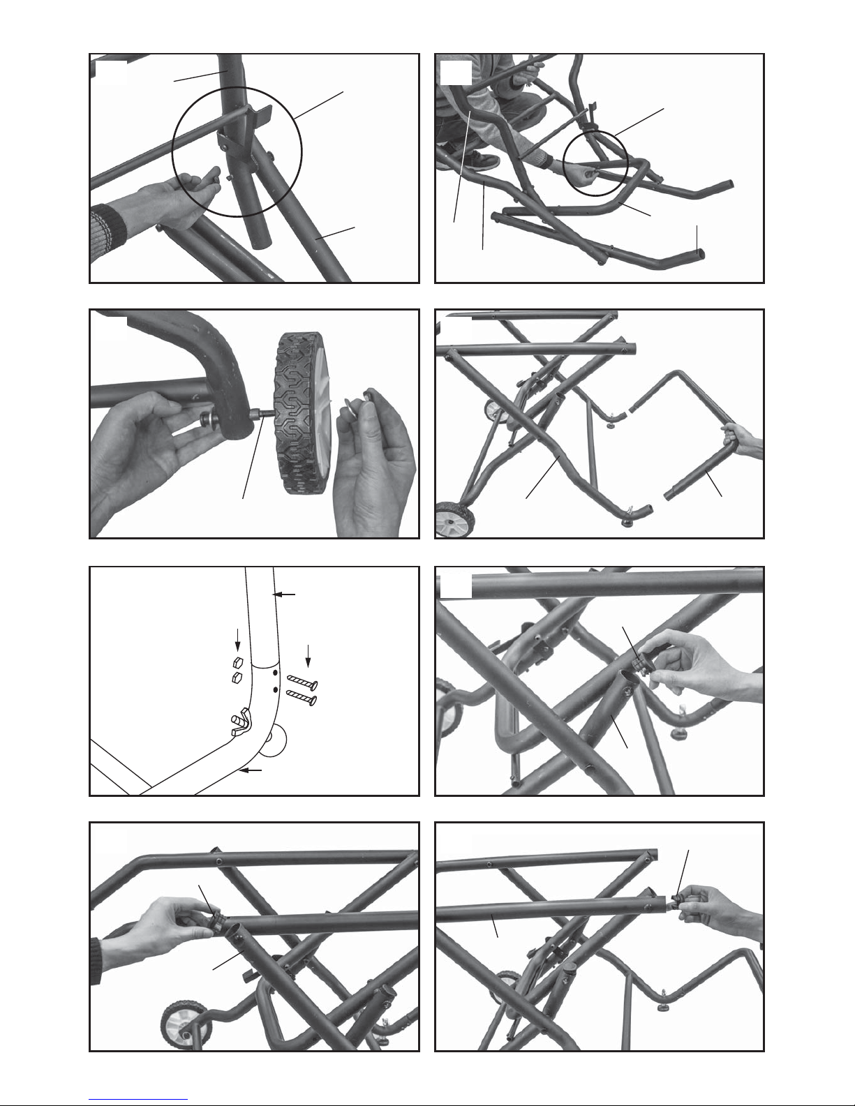
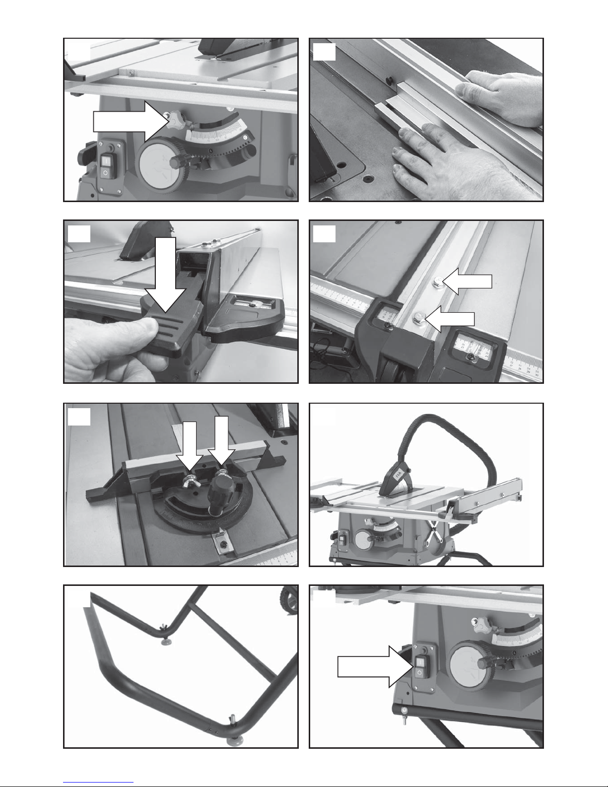
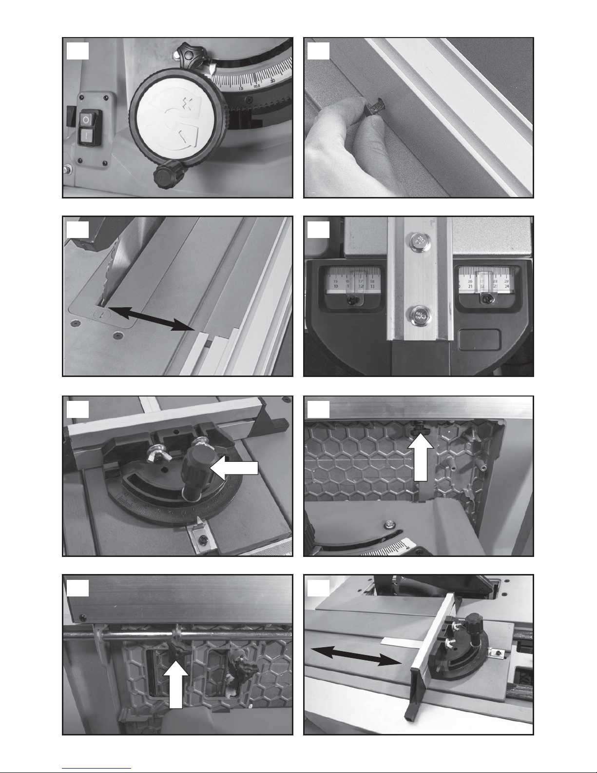
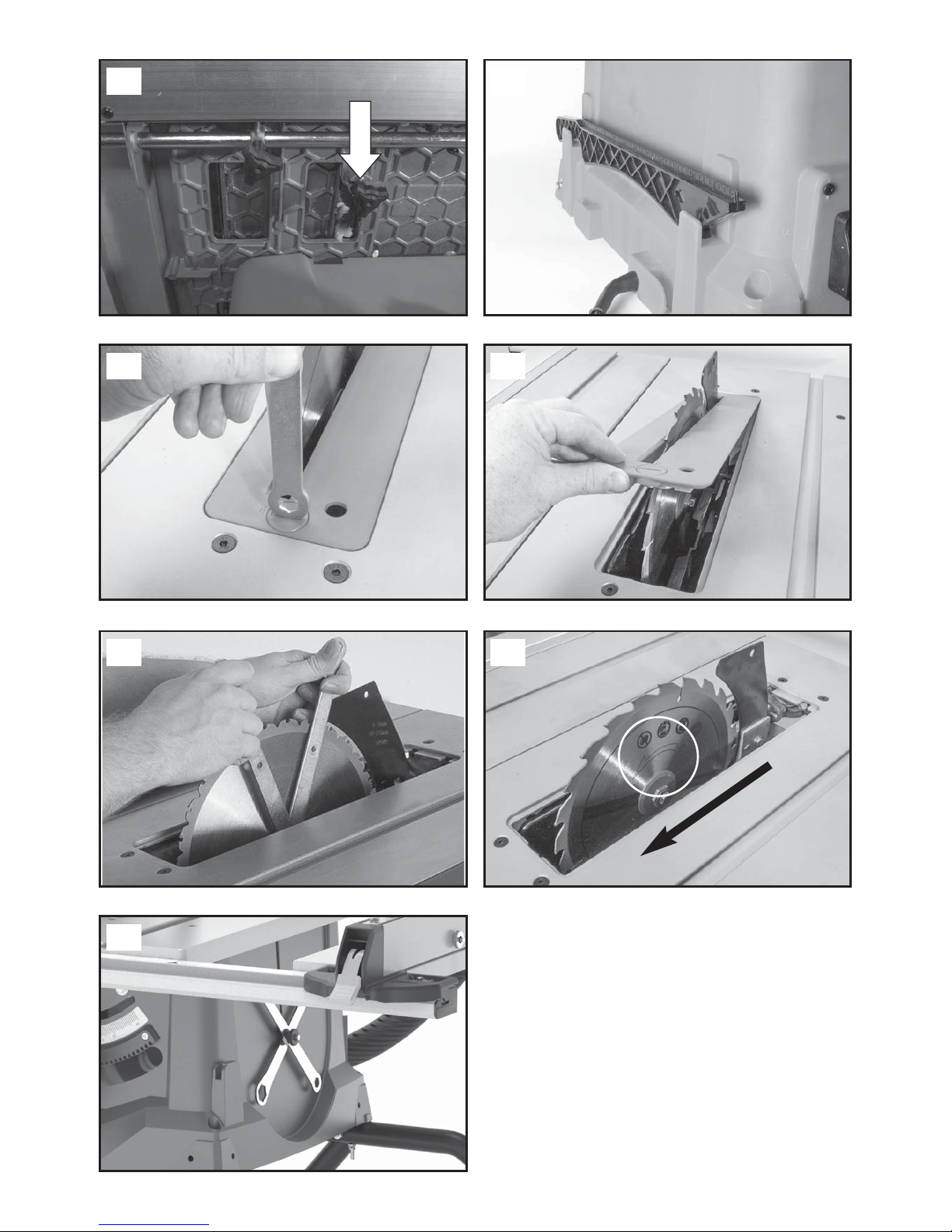
IMPORTANT! Read all safety warnings, instructions, illustrations and specifications provided with this
power tool.
TÄRKEÄÄ! Lue tarkkaavaisesti kaikki tämän työkalun kanssa toimitetut varoitukset, ohjeet ja
spesifikaatiot, ja katso lisäksi kuvat.
VIKTIGT! Läs uppmärksamt alla varningar, instruktioner och specifikationer som bifogas med
detta verktyg och studera bilderna.
VIKTIG! Les nøye gjennom alle advarslene, instruksene og spesifikasjonene som følger med
verktøyet, og se på tegningene.
ВАЖНО! Пpoчтитe вce yкaзaния, инcтpyкции, иллюcтpaции и cпeцификaции, поставляемые
c электроинструментом.
TÄHTIS! Lugege läbi kõik elektrilise tööriista kohta esitatud ohuhoiatused ning tutvuge
tööriista jooniste ja tehniliste andmetega.
SVARĪGI! Izlasiet visus drošības brīdinājumus, instrukcijas, specifikācijas un apskatiet attēlus šī
elektroinstrumenta dokumentācijā.
SVARBU! Perskaitykite visus saugos įspėjimus, visas instrukcijas, paveikslėlius ir techninius
reikalavimus, pateikiamus su šiuo elektriniu įrankiu.
WAŻNE! Prosimy przeczytać wszystkie dotyczące narzędzia ostrzeżenia i instrukcje oraz
przestudiować ilustracje i specyfikację.

11
INTRODUCTION
Thankyou for purchasing this product which has
passed through our extensive quality assurance
process. Every care has been taken to ensure that it
reaches you in perfect condition.
SAFETY FIRST
Before attempting to operate this power tool the
following basic safety precautions should always be
taken to reduce the risk of fire, electric shock and
personal injury. It is important to read the instruction
manual to understand the application, limitations and
potential hazards associated with this tool.
CERTIFICATE OF GUARANTEE
This product is guaranteed for a period of 2 Years,
with effect from the date of purchase and applies only
to the original purchaser. This guarantee only applies
to defects arising from, defective materials and or
faulty workmanship that become evident during the
guarantee period only and does not include
consumable items. The manufacturer will repair or
replace the product at their discretion subject to the
following. That the product has been used in
accordance with the guide lines as detailed in the
product manual and that it has not been
subjected to misuse, abuse or used for a purpose for
which it was not intended. That it has not been taken
apart or tampered with in any way whatsoever or has
been serviced by unauthorised persons or has been
used for hire purposes. Transit damage is excluded
from this guarantee, for such damage the transport
company is responsible. Claims made under this
guarantee must be made in the first instance, directly
to the retailer within the guarantee period. Only under
exceptional circumstances should the product be
returned to the manufacturer. In these case it shall be
the consumer’s responsibility to return the product at
their cost ensuring that the product is adequately
packed to prevent transit damage and must be
accompanied with a brief description of the fault and
a copy of the receipt or other proof of purchase. The
manufacturer shall not be liable for any special,
exemplary, direct, indirect, incidental, or consequential
loss or damage under this guarantee. This guarantee
is in addition to and does not affect any rights, which
the consumer may have by virtue of the Sale of Goods
Act 1973 as amended 1975 and 1999.
STATUTORY RIGHTS
This guarantee is in addition to and in no way affects
your statutory rights.
PRODUCT DISPOSAL
When this product reaches the end of it’s life or is
disposed of for any other reason, it must not be
disposed of in household waste. In order to preserve
natural resources, and to minimise adverse
environmental impact, please recycle or dispose of
this product in an environmentally friendly way. It
should be taken to your local waste recycling centre
or other authorised collection and disposal facility.
If in doubt consult your local waste authority for
information regarding available recycling and / or
disposal options.
HEALTH ADVICE
Warning: When drilling, sanding, sawing or grinding,
dust particles will be produced. In some instances,
depending on the materials you are working with, this
dust can be particularly harmful to you (e.g. lead from
old gloss paint).You are advised to consider the risks
associated with the materials you are working with
and to reduce the risk of exposure.
You should:
Work in a well-ventilated area.
Work with approved safety equipment, such as dust
masks that are specially designed to filter microscopic
particles.
INTENDED USE
The bench-type circular saw is designed for the
slitting and cross-cutting of all types of timber,
commensurate with the machine’s size.
The machine is not to be used for cutting any type of
roundwood.
The machine is to be used only for its prescribed
purpose. Any use other than that mentioned is
considered to be a case of misuse.
The user/operator and not the manufacturer shall be
liable for any damage or injury resulting such cases of
misuse. The user/operator and not the manufacturer
shall be liable for any damage or injury resulting such
cases of misuse.
The machine is to be operated only with suitable saw
blades. It is prohibited to use any type of cutting-off
wheel. To use the machine properly you must also
observe the safety regulations, the assembly
instructions and the operating instructions to be found
in this manual. All persons who use and service the
machine have to be acquainted with this manual and
must be informed about its potential hazards. It is also
imperative to observe the accident prevention
regulations in force in your area. The same applies for
the general rules of occupational health and safety.
Important! When using the equipment, a few safety
precautions must be observed to avoid injuries and
damage. Please read the complete operating
instructions and safety regulations with due care.
Keep this manual in a safe place, so that the
information is available at all times. If you give the
equipment to any other person, hand over these
operating instructions and safety regulations as well.
We cannot accept any liability for damage or
accidents which arise due to a failure to follow these
instructions and the safety instructions.
The manufacturer shall not be liable for any changes
made to the machine nor for any damage resulting
from such changes.

12
Even when the machine is used as prescribed it is still
impossible to eliminate certain residual risk factors.
The following hazards may arise in connection with
the machine’s construction and design:
Contact with the saw blade in the uncovered saw
zone.
Reaching into the running saw blade (cut injuries).
Kick-back of workpieces and parts of workpieces
Saw blade fracturing.
Catapulting of faulty carbide tips from the saw blade.
Damage to hearing if essential ear-muffs are not worn.
Harmful emissions of wood dust when the machine is
used in closed rooms.
Please note that our equipment has not been
designed for use in commercial, trade or industrial
applications.
Our warranty will be voided if the machine is used in
commercial, trade or industrial businesses or for
equivalent purposes.
SPECIFIC SAFETY INSTRUCTIONS
Do not use saw blades which are damaged or
deformed.
Replace the table insert/access plate if worn.
Use only blades as recommended in this manual,
which conform to EN 847-1. When changing a saw
blade ensure that the width of the groove (kerf) cut by
the blade is slightly greater than the thickness of the
riving knife. Also the thickness of the blade body must
not be greater than the thickness of the riving knife.
Take care that the selection of the saw blade is
suitable for the material to be cut.
Wear suitable personal protective equipment when
necessary. This could include:
Hearing protection to reduce the risk of induced
hearing loss.
Respiratory protection to reduce the risk of inhalation
of harmful dust.
Wearing gloves when handling saw blades or rough
material.
Saw blades should be carried in a holder whenever
practicable.
Never perform any operation freehand. This means
using only your hands to support or guide the
workpiece. Always use either the fence or mitre gauge
to position and guide the work.
WARNING! Freehand cutting is a major cause of
accidents.
Never attempt to free a stalled blade without first
turning the saw off. Turn the power off immediately to
prevent damage to the motor.
Provide adequate support for long or wide
workpieces.
Avoid awkward operations and hand positions where
a slip could cause your hand to move into the blade.
Do not operate the appliance with a damaged cord or
plug. If the supply cord is damaged, it must be
replaced by the manufacturer or its service agent or a
similarly qualified person in order to avoid a hazard.
ADDITIONAL SPECIFIC SAFETY RULES FOR
TABLE SAWS
WARNING! Before using your table saw it is important
that you read and understand these safety rules.
Failure to follow these rules could result in serious
injury to the operator or damage to the table saw.
Always use the blade guard. The blade guard must
always be used in every operation.
Hold the work firmly. Against the mitre gauge or rip
fence.
Always use a push stick. Especially when rip cutting
narrow stock.
Keep guards in place and in working order. Always
ensure that the riving knife is fitted and correctly
adjusted. Inspect the riving knife regularly and replace
it if it is worn. Use only a genuine FXA riving knife as
this is a dedicated component for this machine.
Remove adjusting keys and wrenches. Form the habit
of checking to see that keys and adjusting wrenches
are removed from the machine before turning it on.
Do not use in dangerous environment. Do not use
power tools in damp or wet locations, or expose them
to rain. Keep work area well lit. Keep the area well
ventilated.
Keep children away. All children and visitors should be
kept at a safe distance from the work area.
Do not use High Speed Steel (HSS) blades. Ensure
that the correct blade is selected for the material
being cut.
The push stick or push block should always be stored
with the machine when not in use.
Connect the saw to a dust collection device when
sawing wood. The operator should be informed of the
factors that influence exposure to dust e.g. type of
material being cut and the importance of local
extraction (capture or source) and the proper
adjustment hoods/baffles/chutes.
Use a proper extension cord. Make sure any
extension cord is in good condition. When using an
extension cord, be sure to use one heavy enough to
carry the current your machine will draw. An
undersized cord will cause a drop in line voltage
resulting in loss of power and possible overheating.

13
Always use safety glasses. Also use a face or dust
mask if the cutting operation is dusty. Everyday
eyeglasses only have impact resistant lenses, they are
NOT safety glasses.
Maintain tools with care. Keep tools sharp and clean
for best and safest performance.
Disconnect from the power supply before servicing,
cleaning or and when changing accessories, such as
blades.
Check for damaged parts. Before further use of the
tool, a guard or other part that is damaged should be
carefully checked to determine that it will operate
properly and perform its intended function - check for
alignment of moving parts, binding of moving parts,
breakage of parts, mounting, and any other conditions
that may affect its operation. A guard or other part
that is damaged should be properly repaired or
replaced.
Keep hands out of the path of the saw blade.
Never reach around the saw blade.
Turn off machine and wait for saw blade to stop
before making any fence adjustments.
Never pull or carry the tool by the power cord.
Carrying or pulling the tool by the power cord could
cause damage to the insulation or the wire
connections resulting in the possibility of electric
shock or fire.
When transporting the machine use a transportation
device.
Never use the guards for handling or transportation.
During transportation the upper part of the saw blade
must be lowered fully and covered by the guard.
All operators using this machine must read the
instructions and familiarize themselves with the
machines workings.
Never leave the saw running and unattended. Do not
leave the saw until the saw has been switched OFF,
and the blade has come to a complete halt.
Only use saw blades for which the maximum
permissible speed is not lower than the maximum
spindle speed of table saws and which are suitable for
the material to be cut.
Do not cut rebates or grooves without fitting a suitable
guard, e.g. a tunnel-type guard, over the saw table.
Circular saws must not be used for slotting jobs
(cutting grooves which end in the workpiece).
The floor around the machine must be level, clean and
free of loose particles, such as chips and cutting
residues.
Always stand to the side of the saw blade when
working with the saw.
Do not remove any cutting residues or other parts of
workpieces from the cutting zone while the machine is
running and the saw unit is not at rest.
Make sure that the machine is always secured on a
workbench or a table if at all possible.
Support long workpieces (e.g. with a roller table) to
prevent them sagging at the end of a cut.
Attention! Never remove loose splinters, chips or
jammed pieces of wood while the saw blade is
running. Switch off the machine to troubleshoot or
remove jammed pieces of wood. - Disconnect the
main power plug.
Refitting, including adjusting and measuring works,
and cleaning must be carried out only when the motor
is switched off. - Disconnect the main power plug.
Before switching on again, ensure that keys and
adjustment tools have been removed.
WARNING! This electric tool generates an
electromagnetic field during operation. This field can
impair active or passive medical implants under
certain conditions. In order to prevent the risk of
serious or deadly injuries, we recommend that
persons with medical implants consult with their
physician and the manufacturer of the medical implant
prior to operating the electric tool.
SAFETY INSTRUCTIONS FOR THE HANDLING OF
SAW BLADES
Only use insertion tools if you have mastered their
use.
Observe the maximum speed. The maximum speed
specified on the insertion tool may not be exceeded. If
specified, observe the speed range.
Observe the motor / saw blade direction of rotation.
Do not use any insertion tools with cracks. Sort out
cracked insertion tools. Repairs are not permitted.
Clean grease, oil and water off of the clamping
surfaces.
Do not use any loose reducing rings or bushes for the
reducing of holes on saw blades.
Make sure that fixed reducer rings for securing the
insertion tool have the same diameter and have at
least 1/3 of the cutting diameter.
Make sure that fixed reducer rings are parallel to each
other.
Handle insertion tool with caution. They are ideally
stored in the originally package or special containers.
Wear protective gloves in order to improve grip and to
further reduce the risk of injury.
Prior to the use of insertion tools, make sure that all
protective devices are properly fastened.

14
Prior to use, make sure that the insertion tool meets
the technical requirements of this electric tool and is
properly fastened.
Only use the supplied saw blade for sawing
operations in wood, materials similar to wood, plastics
and non-ferrous metals (except for magnesium and
alloys containing magnesium).
RESIDUAL RISKS
The machine has been built according to the state of
the art and the recognised technical safety
requirements. However, individual residual risks can
arise during operation.
Health hazard due to electrical power, with the use of
improper electrical connection cables.
Furthermore, despite all precautions having been met,
some non-obvious residual risks may still remain.
Residual risks can be minimised if the „safety
instructions“ and the „Proper use“ are observed along
with the whole of the operating instructions.
Do not load the machine unnecessarily: excessive
pressure when sawing will quickly damage the saw
blade, which results in reduced output of the machine
in the processing and in cut precision.
When cutting plastic material, please always use
clamps: the parts which should be cut must always be
fixed between the clamps.
Avoid accidental starting of the machine: the
operating button may not be pressed when inserting
the plug in an outlet.
Use the tool that is recommended in this manual. In
doing so, your saw provides optimal performance.
Hands may never enter the processing zone when the
machine is in operation. Release the handle button
and switch off the machine prior to any operations.
Prior to any adjustment, maintenance or service work
disconnect the mains power plug!
GENERAL SAFETY RULES
WARNING! Read all instructions Failure to follow all
instructions listed below may result in electric shock,
fire and/or serious injury. The term "power tool" in all
of the warnings listed below refers to your mains
operated (corded) power tool or battery operated
(cordless) power tool.
SAVE THESE INSTRUCTIONS
1) WORK AREA
a) Keep work area clean and well lit. Cluttered and
dark areas invite accidents.
b) Do not operate power tools in explosive
atmospheres, such as in the presence of
flammable liquids, gases or dust. Power tools
create sparks which may ignite the dust or fumes.
c) Keep children and bystanders away while
operating a power tool. Distractions can cause you
to lose control.
2) ELECTRICAL SAFETY
a) Power tool plugs must match the outlet. Never
modify the plug in any way. Do not use any
adapter plugs with earthed (grounded) power
tools. Unmodified plugs and matching outlets will
reduce risk of electric shock.
b) Avoid body contact with earthed or grounded
surfaces such as pipes, radiators, ranges and
refrigerators.
There is an increased risk of electric shock if your
body is earthed or grounded.
c) Do not expose power tools to rain or wet
conditions. Water entering a power tool will
increase the risk of electric shock.
d) Do not abuse the cord. Never use the cord for
carrying, pulling or unplugging the power tool.
Keep cord away from heat, oil, sharp edges or
moving parts. Damaged or entangled cords
increase the risk of electric shock.
e) When operating a power tool outdoors, use an
extension cord suitable for outdoor use. Use of a
cord suitable for outdoor use reduces the risk of
electric shock.
3) PERSONAL SAFETY
a) Stay alert, watch what you are doing and use
common sense when operating a power tool. Do
not use a power tool while you are tired or under
the influence of drugs, alcohol or medication.
A moment of inattention while operating power
tools may result in serious personal injury.
b) Use safety equipment. Always wear eye
protection. Safety equipment such as dust mask,
non-skid safety shoes, hard hat, or hearing
protection used for appropriate conditions will
reduce personal injuries.
c) Avoid accidental starting. Ensure the switch is in
the off position before plugging in. Carrying power
tools with your finger on the switch or plugging in
power tools that have the switch on invites
accidents.
d) Remove any adjusting key or wrench before
turning the power tool on.
A wrench or a key left attached to a rotating part
of the power tool may result in personal injury.
e) Do not overreach. Keep proper footing and
balance at all times. This enables better control of
the power tool in unexpected situations.
f) Dress properly. Do not wear loose clothing or
jewellery. Keep your hair, clothing and gloves
away from moving parts. Loose clothes, jewellery
or long hair can be caught in moving parts.

15
g) If devices are provided for the connection of dust
extraction and collection facilities, ensure these
are connected and properly used. Use of these
devices can reduce dust related hazards.
4) POWER TOOL USE AND CARE
a) Do not force the power tool. Use the correct
power tool for your application. The correct power
tool will do the job better and safer at the rate for
which it was designed.
b) Do not use the power tool if the switch does not
turn it on and off. Any power tool that cannot be
controlled with the switch is dangerous and must
be repaired.
c) Disconnect the plug from the power source before
making any adjustments, changing accessories, or
storing power tools. Such preventive safety
measures reduce the risk of starting the power
tool accidentally.
d) Store idle power tools out of the reach of children
and do not allow persons unfamiliar with the
power tool or these instructions to operate the
power tool. Power tools are dangerous in the
hands of untrained users.
e) Maintain power tools. Check for misalignment or
binding of moving parts, breakage of parts and
any other condition that may affect the power
tools operation. If damaged, have the power tool
repaired before use. Many accidents are caused
by poorly maintained power tools.
f) Keep cutting tools sharp and clean. Properly
maintained cutting tools with sharp cutting edges
are less likely to bind and are easier to control.
g) Use the power tool, accessories and tool bits etc.,
in accordance with these instructions and in the
manner intended for the particular type of power
tool, taking into account the working conditions
and the work to be performed. Use of the power
tool for operations different from intended could
result in a hazardous situation.
5) SERVICE
a) Have your power tool serviced by a qualified repair
person using only identical replacement parts. This
will ensure that the safety of the power tool is
maintained.
COMPONENTS & CONTROLS (FIG 1)
PARTS LIST (FIG 2)
A. Bevel adjustment hand wheel
B. Bevel locking knob
C. Blade guard
D. Dust extraction hose
E. Rip fence
F. Rip fence locking handle
G. Tool storage
H. Right hand side table extension locking knob
(1 front, 1 rear)
I. Wheel
J. Latching pin
K. On/Off Switch
L. Push stick storage
M. Left hand side table extension locking knob
(1 front, 1 rear)
N. Sliding carriage unlocking pin
O. Sliding mitre fence
P. Riving knife
Q. Blade
1. Flat end caps x 6
2. Round end caps x 2
3. M8 x 78mm bolt x 8
4. M8 nut x 8
5. Spacer x 8
6. M6 x 75mm bolt x 4
7. M6 silver washer x 4
8. M6 black washer x 4
9. M6 nut x 4
10. M5 x 50mm bolt x 2
11. M5 x 40mm bolt x 4
12. M5 nut x 6
13. Wheel bolt x 2
14. Wheel washer x 2
15. Wheel small washer x 2
16. Wheel nut x 2

16
PARTS LIST (FIG 3)
UNPACKING
Caution! This packaging contains sharp objects. Take
care when unpacking. Remove the machine, together
with the accessories supplied, from the packaging.
Check carefully to ensure that the machine is in good
condition and account for all the accessories listed in
this manual. Also make sure that all the accessories
are complete. If any parts are found to be missing, the
machine and its accessories should be returned
together in their original packaging to the retailer.
Do not throw the packaging away, keep it safe
throughout the guarantee period, then recycle if
possible, otherwise dispose of it by the proper means.
Do not let children play with empty plastic bags due
to the risk of suffocation.
ASSEMBLY
To assemble this saw you will need: Cross head
screwdriver, 8mm & 10mm spanner or socket wrench,
13mm Socket wrench, 5mm allen key and a rubber
mallet.
Unpack all components including fixings and
familiarise yourself with them before attempting to
assemble the machine. Enlist competent help when
assembling this machine. Use the rubber mallet to aid
assembly.
Warning! This machine is heavy. Enlist competent
help when moving or lifting this machine.
STEP 1
Select the components labelled 23 and 31. Attach 31
to 23 using the fixings 3,4 & 5 (Fig.4). Make sure the
spacer (5) is between components 23 & 31 and the
bolt (3) is on the outside and the nut (4) on the inside.
Repeat on the other side.
STEP 2
Attach component 20 to the outside of 23 using the
fixings labelled 3, 4 and 5. Make sure the spacer (5) is
between components 20 & 23 and the bolt (3) is on
the outside and the nut (4) on the inside. Do not over
tighten. Repeat on the other side. (Fig.5).
STEP 3
Select the components labelled 17 and 25. Attach 25
to 17 using the fixings 10 and 12 (Fig.6).
STEP 4
Attach the two components that have been
assembled in Steps 1-3 using the fixings labelled 3, 4
and 5. Make sure the spacer (5) is between
components 20 & 17 and the bolt (3) is on the outside
and the nut (4) on the inside. Do not over tighten.
Repeat on the other side. (Fig.7 & 8).
STEP 5
Attach the bottom of component 17 to the outside of
component 31 using the fixings labelled 3, 4 and 5.
Make sure the spacer (5) is between components 20 &
31 and the bolt (3) is on the outside and the nut (4) on
the inside. Do not over tighten. Repeat on the other
side. (Fig.9).
STEP 6
Attach the wheels 29 to their service position on
component 17 (Fig.10) using fixings 13,14,15 & 16. Do
not over tighten the wheels, as this will prevent them
from moving freely.
STEP 7
Select the components labelled 20 and 22. Attach
component 22 to 20 using the fixings labelled 11 and
12 (Fig.11 & 12).
STEP 8
Place the flat end caps (1) in the positions shown in
Fig.13-15. Repeat on the both sides of components
17, 20 & 23.
STEP 9
Place the round end caps (2) into the end component
23 (Fig.16). Repeat on the other side.
STEP 10
Turn the main body of the machine upside down and
place on a clean, secure and sturdy workbench or
similar.
Position the leg assembly onto the main body of the
machine (Fig.17).
Attach the leg assembly to the machines main body
using fixings 6,7,8 & 9 (Fig.18). Repeat this process on
all 4 corners.
Enlist competent help in turning the table saw over.
Ensure the locking latch is locked into place before
using, Fig.19.
The stand assembly is now complete.
17. Stand component x 1
18. Push stick
19. Rip fence
20. Stand component x 1
21. Blade guard
22. Stand component x 1
23. Stand component x 2
24. Dust extraction hose
25. Stand component x 1
26. Locking latch
27. Mitre gauge
28. Rip fence face plate
29. Wheel
30. Latching pin
31. Stand component x 1

17
STORING AND TRANSPORTING THE MACHINE
Whilst holding the handles press the locking lever with
your foot, Fig.20.
Slowly push the main body upwards, Fig.21, until it is
upright. The machine can now be stored or
transported as shown in Fig.22.
DEPLOYING THE LEGS
The legs are stored underneath the machines main
body.
Release the retaining latch (Fig.23).
Deploy the legs.
Ensure that the legs are secured into their service
position.
The latch must deploy and lock the legs securely in
their service position.
Note: This machine is heavy. Competent help should
be enlisted when moving this machine. Competent
help may also be required when deploying the leg
assembly and/or storing the leg assembly underneath
the machine.
RIVING KNIFE
Warning! Before fitting the riving knife make sure the
machine is disconnected from the mains supply.
The riving knife must be fitted correctly before using
the table saw.
The riving knife has two functions:
It prevents the work-piece from binding as it passes
through the blade.
It provides a suitable connection point for the blade
guard.
To fit and/or check the riving knife:
Remove the table access plate by turning the fixing
screw ¼ of a turn (Fig.24). Lift the access plate from
the machine (Fig.25) and store in a safe place for later
use.
Raise the blade to its highest position by turning the
bevel adjustment hand wheel clockwise, Fig.26.
Loosen the riving knife fixing bolt by several turns and
raise it to its highest point (Fig.27).
Slide the riving knife (it is slotted for convenience)
between the fixing plate and mounting block (Fig.27).
Ensure that the mounting blocks projecting lugs
engage with the slot in the riving knife.
Adjust the riving knife so that it is between 3 – 5mm
from the saw blade. The tip of the riving knife shall not
be lower than 5mm from the tooth peak. (Fig.28).
When correct alignment is achieved tighten the fixing
bolt.
Check the saw blade rotates freely and teeth are
within3-5mmoftherivingknife.
Re-install the table access plate.
INSTALLING THE BLADE GUARD
The blade guard must be attached to the machines
riving knife. Note: The machine should never be used
without this guard in its service position.
Warning! The machine must be disconnected from
the mains supply when installing the blade guard.
To install the blade guard raise the blade to its full
height by turning the bevel adjustment hand wheel
clockwise. This will reveal the riving knife.
The guards locating pin should be positioned through
the hole machined in the riving knife and the locking
nut fitted to one side. The blade guard must move up
and down easily and smoothly, so do not over-tighten
this nut (Fig.29).
Check the operation of the blade guard. Ensure that it
is working efficiently and covers the crown of the
blade.
Lower the blade a little and recheck that the blade
guard operation.
When satisfied that the blade guard works throughout
the blades height adjustment range, check that the
guard works equally well with the blade at a bevel
angle (Fig.30).
To tilt the blade loosen the bevel locking knob
(Fig.31).
Push the hand-wheel in against its bias spring until it
engages with the tilt rack.
Use the hand-wheel to set the required angle.
Check that when the blade is fully lowered, the blade
guard is in contact with the table top.
INSTALLING THE RIP FENCE
This machine has a two piece rip fence.
The rip fence face plate labelled V must be attached
to the rip fence labelled M using the bolts and finger
nuts provided.
Insert the bolts through the holes on the left hand side
of the rip fence and loosely tighten the finger nut on
the right side.
Slide the rip fence face plate onto the rip fence over
the heads of the bolts (Fig.32).
Tighten the two finger nuts.
To attach the Rip Fence:
Hook the rear of the rip fence guide over the rear rip
fence rail.
With the handle in its upper position, locate the front
of the rip fence over the front rip fence rail.
Push the handle down to lock the rip fence in place
(Fig. 33).

18
ADJUSTING THE RIP FENCE
When installed to the machine, the rip fence should be
checked to ensure that it lies parallel to the blade.
Raise the blade to its full height.
Rest a straight-edge or similar against the blade.
Bring the rip fence up to the straight-edge and check
if it is parallel.
If adjustment is needed, loosen the two hex headed
screws located on the rip fence (Fig.34) using a
suitable wrench, and adjust the fence as required.
Tighten and re-check the rip fence when correct
alignment has been achieved.
Lower the blade.
INSTALLING THE MITRE GAUGE
To attach the face plate of the mitre gauge slide the
attachment screws through the two holes in mitre
gauges vertical face and secure in place with the
thumb nuts (Fig. 35).
The mitre gauge is usually employed on the left hand
side of the table and runs in an inverted T slot in the
table top.
INSTALLING THE DUST EXTRACTION HOSE
Attach one end of the hose to the blade guard and
place the other end to the pipe on the back of the
machine, Fig.36. A vacuum cleaner or workshop dust
extraction device can be connected to the extraction
port found at the rear of the machine if required
MOVING THE TABLE SAW
Warning! Ensure that the machine is disconnected
from the mains supply and that the power cord is
securely stored on the machine.
Release the latching pin.
Grasp the transportation handle (Fig.37).
Gently and slowly lift the handle, allowing the machine
to maintain balance and stability.
Wheel the machine to its new location.
OPERATIONS
ON/OFF SAFETY SWITCH (FIG.38)
Warning! Before operating the ON/OFF switch make
sure that the blade guard is correctly installed and
operating properly.
The saw can be switched on by pressing the green
pushbutton ‘I’.
The red pushbutton ‘0’ has to be pressed to switch off
the saw.
Warning! Never start the machine until all safety
checks and procedures have been carried out.
RAISING/LOWERING THE BLADE (FIG.39)
Warning! Only make adjustments to the machine
when the machine is switched OFF and the blade is
stationary.
Note: This machine is equipped with a dual function
handwheel. In its ‘normal’ (outer) position the hand-
wheel is used to raise or lower the blade. When the
hand-wheel is pushed in against its bias spring it
engages with the curved toothed rack incorporated in
the machines main body. This allows the handwheel
to be used to adjust the tilt/bevel angle of the blade.
To raise or lower the blade:
Ensure that the hand-wheel is in its ‘normal’ position.
Turn counter clockwise to lower the blade.
Turn clockwise to raise the blade.
TILTING THE BLADE
Loosen the bevel locking knob.
Push the hand-wheel in against its bias spring until it
engages with the tilt rack.
Use the hand-wheel to set the required angle. An
angle gauge to aid setting can be found behind the
hand-wheel.
Tighten the bevel locking knob when the required
angle is achieved.
Allow the hand-wheel to return to its ‘normal’ position.
RIP FENCE
This machine is fitted with a two piece rip fence. We
recommend that the rip fence is normally used in
conjunction with its adjustable face plate.
The rip fence should normally be positioned to the
right hand side of the blade. It is locked in position by
using the locking lever.
Push down to lock, and pull up to unlock.
Forwards and backwards adjustment of the rip fence
face plate is possible. Loosen the finger nuts and slide
the rip fence face plate to the desired position.
Tighten the wing nuts securely (Fig.40).
We recommend you adjust and align the back of the
rip fence face plate level with the front of the saw
blade (Fig.41).
DUAL READ SCALE
This machine has a dual read scale that shows the
distance from the blade to the rip fence through a
viewing window. This can be used to aid setting the
cutting distance from the blade to the rip fence. With
the rip fence face plate attached, use the black scale
to set the distance of the rip fence. If you should need
to use the rip fence without the face plate, use the
orange scale.

19
Note: When using the rip fence to the left hand side of
the blade use the left viewing window to read the
scales. When using the rip fence to the right hand side
of the blade, use the right viewing window to view the
scale (Fig.42). The scale should be regarded as a
useful guide. It is not a substitute for careful and
accurate measuring by hand.
MITRE GAUGE
The mitre gauge can be used on either side of the
table and runs in inverted ‘T’ slots machined into the
sliding carriage and the table top.
Turn the vertical handle counter-clockwise to unlock
the mitre gauge, and adjust to the required mitre
angle. Turn the handle clockwise to lock the mitre
gauge at the chosen angle, Fig.43.
Note: The face plate of the mitre gauge should be
adjusted so that it passes close to, but does not
touch the blade guard as it slides past during a cut.
Adjust by loosening the finger nuts and sliding the
faceplate to the required position. Securely tighten the
finger nuts (Fig.35).
Note: The mitre gauge can be set at any angle
between 60˚ left and 60˚ right.
EXTENDING THE TABLE
The table top can be extended to the right and left
sides creating extra workpiece support when cutting
large or wide boards etc. Both sides of the table can
be extended at the same time, or just one side at a
time as required.
To extend the table to the right side:
Pull up the rip fence locking lever and ensure that the
rip fence is free to move.
Alternatively it may be convenient to temporarily
remove the rip fence from the machine.
Loosen the right hand side table extension locking
knob lever found under the table on the right. (Fig. 44).
Deploy the table extension to give the required
workpiece support.
Tighten the right hand side table extension locking
knob to lock the table in the required position.
Re-attach and/or adjust the rip fence as required.
When cutting is completed return the table to its
original setting.
To extend the table to the left hand side:
Loosen the two left hand side table extension locking
knobs (one to the front and one to the rear of the
machine) underneath the left hand side of the
machines table (Fig.45).
Deploy the table extension.
Tighten the locking knobs.
When cutting is completed return the table to its
original setting.
SLIDING CARRIAGE
This machine is fitted with a sliding carriage (Fig.46) to
the left hand side of the blade. This facility can be
particularly useful when cross-cutting small section
material such as metal box section or extrusions etc.
The sliding carriage system can also be very useful
(when used in conjunction with a secured mitre gauge)
for repetitive cross-cutting.
Warning! The machine must be switched off and the
blade stationary whenever adjustments etc. are being
made to the machine or the work-piece.
Unlock the pin under the sliding carriage by pulling
out the knob (Fig.47) and turning it 90˚ allowing it to
rest in its unlocked position. You can now use the
sliding carriage.
To lock the sliding carriage again, reverse the
unlocking motion.
TABLE SAW OPERATION
Warning! Never attempt freehand cuts on this
machine.
Always use the appropriate guide or fence to minimise
the possibility of the blade binding and kickback.
We recommend that the saw blade protrudes through
the material to be cut by approximately 3mm. Adjust
the height of the blade as previously described. This
machine is not suitable for cutting rebates or stopped
grooves.
A vacuum cleaner or workshop dust extraction device
can be connected to the extraction port found at the
rear of the machine if required.
CROSSCUTTING
Cross cutting requires the use of the mitre gauge to
position and guide the work. Place the workpiece
against the mitre gauge. Switch on the saw and allow
to reach full operating speed before advancing both
the mitre gauge and workpiece toward the saw blade.
The mitre gauge may be used in either table T-slot,
however, most operators prefer the left groove for
average work. When bevel cutting (blade tilted), use
the right side table T-slot so that it doesn’t interfere
with the tilted saw blade.
Start the cut slowly and hold the workpiece firmly
against the mitre gauge and the table. One of the
rules in running a saw is that you never hang onto or
touch a free piece of work. Hold the supported piece,
not the free piece that is cut off. The feed in cross
cutting continues until the workpiece is cut in two,
then the mitre gauge and workpiece are pulled back
to the starting point. Before pulling the workpiece
back it is good practice to give the workpiece a little
sideways shift to move it away from the saw blade.

20
Never pick up any short length of free work from the
table while the saw is running. A smart operator never
touches a cut-off piece unless it is at least a foot long.
Never use the rip fence as a cut-off gauge when cross
cutting.
MITRE CROSSCUTTING
Mitre crosscutting is cutting the work-piece at an
angle of other than 90˚. Set the Mitre Gauge to the
desired angle, tighten and proceed as the
crosscutting instructions previous.
BEVEL CROSSCUTTING
Bevel crosscutting is the same as crosscutting but
with the blade tilted at an angle.
Tilt the blade to the desired angle as previously
described, and ensure that it is locked in place.
Set the Mitre Gauge to 0˚ and adjust the faceplate so
that it will not touch or foul the saw blade or blade
guard as it travels past.
Hold the work-piece against the Mitre Gauge and
make your cut.
COMPOUND MITRE CUTTING
Compound mitre cutting is a combination of mitre
cutting and bevel crosscutting.
Adjust the mitre gauge and the blade to the desired
angles.
Lock both in place.
Check that the mitre gauge will pass the saw blade
without fouling. Adjust the mitre gauge faceplate if
necessary.
Place the material against the mitre gauge and make
your cut.
RIP CUTTING
Ripping is the operation of making a lengthwise cut
through a board, the rip fence is used to position and
guide the work. One edge of the workpiece rides
against the rip fence while the flat side of the board
rests on the table. Since the work is pushed along the
fence, it must have a straight edge and make solid
contact with the table.
Start the motor and advance the workpiece holding it
down and against the fence. Never, stand in the line
of the saw cut when ripping. Hold the workpiece with
both hands and push it along the fence and into the
saw blade. The work can then be fed through the saw
blade with one or two hands.
When this is done the workpiece will either stay on the
table, tilt up slightly and be caught by the rear end of
the guard or slide off the table to the floor. Alternately,
the feed can continue to the end of the table, after
which the work is lifted and brought back along the
outside edge of the fence. The waste stock remains
on the table and is not touched with the hands until
the saw is stopped unless it is a large piece allowing
safe removal.
BEVEL RIP CUTTING
When bevel ripping material 150mm or narrower use
the rip fence on the right hand side of the blade only.
MAKING A NON-THROUGH CUT
Non-through cuts can be made with the grain (ripping)
or across the grain (cross cut).
Non-through cuts are needed for cutting grooves,
rabbets and dadoes. This is the only type of cut that
the blade gets covered by the workpiece and is made
without the blade guard installed.
Make sure the blade guard is reinstalled after this type
of cut is done.
For non-through cuts, position the riving knife in the
“down” position, set the blade to the correct height
and tighten the blade height locking knob. Turn on the
saw and allow the blade to come up to speed, use the
push stick to feed the workpiece into blade.
PUSH STICK
A plastic push stick is provided with the machine and
has its own dedicated storage brackets to the left
hand side of the machines main body (Fig.48). When
not in use store the push stick on the machine.
Note: If the push stick becomes damaged it should be
replaced. If the operator makes their own push stick,
we recommend that it follows the same pattern as
that supplied.
MAINTENANCE
Warning! Ensure that the machine is disconnected
from the mains supply before any maintenance tasks
or adjustments are attempted.
CHANGING THE BLADE
Note: We recommend that the operator wears
protective gloves when handling or changing the
machines blade.
Disconnect the machine from the power supply.
Remove the top blade guard.
Remove the table access plate by turning the fixing
screw ¼ of a turn (Fig.49). Lift the access plate from
the machine (Fig.50) and store in a safe place for later
use.
Safely store the access plate for future use.
Raise the blade to its highest position.
Use the two blade changing tools provided. One to
hold the motor arbor, and the other to remove the
arbor nut (Fig.51).
Remove the nut, outer flange and blade.
Fit the new blade. Ensure that the teeth are facing to
the front of the saw, and that the arrow on the blade
is in line with the motor direction (Fig.52).
Replace the outer flange and nut and tighten securely
with the spanners provided. Check that both blade
flanges are in contact with the blade.
Table of contents
Languages: