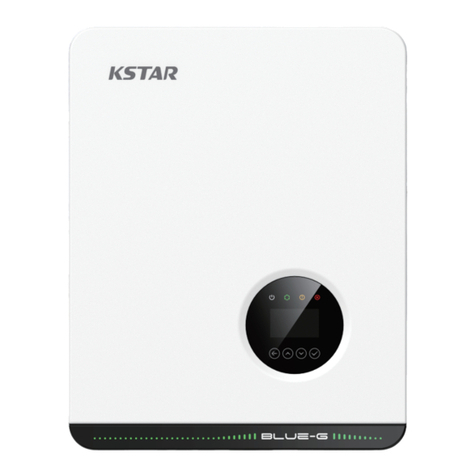
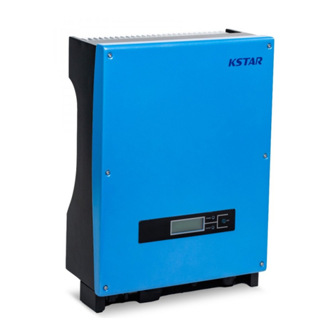
KStar KSG-120CL-M0/M3 User manual

202106 Ver:1.0
Shenzhen Kstar New Energy Company Limited
Add:Kstar Industrial Park, Guangming Hi-Tech Park,
shenzhen ,P.R.CHINA
Tel:0755-21389008 Fax:0755-21389008
Web:www.kstar.com
PV Grid-Connected Inverter
User Manual
KSG-120CL-M0/M3

All Rights Reserved
All Rights Reserved
No part of this document can be reproduced in any form or by any means without the
prior written permission of Shenzhen Kstar New Energy Company Limited
(hereinafter "KSTAR").
and other trademarks used in this manual are owned byKSTAR
Shenzhen Kstar New Energy Company Limited.
All other trademarks or registered trademarks mentioned in this document are
owned by their respective owners.
Trademarks
Software Licenses
It is prohibited to use data contained in firmware or software developed by
KSTAR, in part or in full, for commercial purposes by any means.
It is prohibited to perform reverse engineering, cracking, or any other operations
that compromise the original program design of the software developed by
KSTAR.
User Manual
Ⅰ

Symbol Explanation
Indicates a situation that, if not avoided, could result in
equipment or property damage.
Indicates additional information, emphasized contents or tips
that may be helpful, e.g. to help you solve problems or save time.
About This Manual
The manual mainly describes the product information, guidelines for
installation,operation and maintenance. The manual cannot include complete
information about the photovoltaic (PV) system. You can get additional information
about other devices at or on the webpage of the respective www.kstar.com
component manufacturer.
Validity
This manual is valid for the following inverter types:
KSG-120CL-M0/M3
They will be referred to as “inverter” hereinafter unless otherwise specified.
Target Group
This manual is intended for:
qualified personnel who are responsible for the installation and commissioning
of theinverter;
inverter owners who will have the ability to interact with the inverter.
How to Use This Manual
Read the manual and other related documents before performing any work on the
inverter is carried out. Documents must be stored carefully and be available at all
times.The contents of the manual will be periodically updated or revised due to the
product development. It is probably that there are changes of manual in the
subsequent inverter edition. The latest manual can be acquired via visiting the
website at www.kstar.com.
Symbols
Important instructions contained in this manual should be followed during
installation,operation and maintenance of the inverter. They will be highlighted by
the following symbols.
Symbol Explanation
Indicates a hazard with a high level of risk that, if not voided,
will result in death or serious injury.
Indicates a hazard with a medium level of risk that, if not
avoided,could result in death or serious injury.
Indicates a hazard with a low level of risk that, if not avoided,
could result in minor or moderate injury.
User Manual User Manual
Ⅱ Ⅲ

Ⅴ
All Rights Reserved ......................................................................................... I
About This Manual ...........................................................................................II
1 Safety .........................................................................................................1
1.1 PV Panels................................................................................................1
1.2 Utility Grid...............................................................................................1
1.3 Inverter...................................................................................................2
1.4 Skills of Qualified Personnel.....................................................................3
2 Product Introduction...................................................................................4
2.1 Intended Usage......................................................................................4
2.2 Product Introduction................................................................................5
2.2.1 Model Description.............................................................................5
2.2.2 Appearance......................................................................................6
2.2.3 Dimensions......................................................................................6
2.2.4 LED Board........................................................................................7
2.2.5 DC Switch........................................................................................7
2.3 Circuit Diagram.......................................................................................7
2.4 Function Description...............................................................................8
3 Unpacking and Storage.........................................................................10
3.1 Unpacking and Inspection......................................................................10
3.2 Identifying the Inverter...........................................................................10
3.3 Scope of Delivery..................................................................................12
3.4 Inverter Storage....................................................................................12
4 Mechanical Mounting............................................................................14
4.1 Safety during Mounting..........................................................................14
4.2 Location Requirements..........................................................................14
4.2.1 Installation Environment Requirements.............................................14
4.2.2 Carrier Requirements......................................................................15
4.2.3 Installation Angle Requirements.......................................................15
4.2.4 Installation Clearance Requirements................................................16
4.3 Installation Tools...................................................................................18
4.4 Moving the Inverter................................................................................19

Ⅵ Ⅶ
4.4.1 Manual Transport ............................................................................19
4.4.2 Hoisting Transport ...........................................................................19
4.5 Dimensions of mounting-bracket ..............................................................20
4.6 PV Bracket-Mounted Installation ...............................................................21
4.6.1 Preparation before Mounting .............................................................21
4.6.2 Mounting Steps ................................................................................21
4.7 Wall-Mounted Installation ........................................................................23
4.7.1 Preparation before Mounting .............................................................23
4.7.2 Mounting Steps ................................................................................23
5 Electrical Connection 26........................................................................26
5.1 Safety Instructions ..................................................................................26
5.2 Terminal Description ...............................................................................26
5.3 Electrical Connection Overview ................................................................28
5.4 Additional Grounding Connection .............................................................30
5.4.1 Additional Grounding Requirements ..................................................30
5.4.2 Connection Procedure ......................................................................30
5.5 Opening the Wiring Compartment .............................................................31
5.6 AC Cable Connection ..............................................................................32
5.6.1 AC Side Requirements .....................................................................32
5.6.2 Requirements for OT/DT Terminal .....................................................34
5.6.3 Aluminium Cable Requirements .........................................................34
5.6.4 Connection Procedure ......................................................................35
5.7 DC Cable Connection ..............................................................................38
5.7.1 PV Input Configuration .....................................................................39
5.7.2 Connection Procedure ......................................................................40
5.7.3 Installing the PV Connectors .............................................................41
5.8 RS485 Communication ............................................................................42
5.8.1 Interface Description. .......................................................................42
5.8.2 RS485 Communication System .........................................................42
5.8.3 Connection Procedure(Terminal Block) .............................................43
5.9 PLC Communication Connection ..............................................................45
5.10 ...................................45Wiring of Tracking System Power Cable(Optional)
5.11 Closing the Wiring Compartment ............................................................46
6. ...................................................................................47Commissioning
6.1 Inspection before Commissioning...........................................................47
2 Commissioning Procedure.....................................................................47 6.
7. Bluetooth APP Settings....................................................................48
7.1 Overview...............................................................................................48
7.2 APP download........................................................................................48
7.3 Bluetooth connection..............................................................................48
7.4 Basic information interface......................................................................50
7.5 Query interface.......................................................................................51
7.6 Setting interface......................................................................................51
7.6.1 Set page information.......................................................................53
7.6.2 Related parameters setting interface................................................54
7.6.3 Set parameter information...............................................................55
7.7 Statistics interface.................................................................................58
8 System Decommissioning. .........................................................................59
8.1 Disconnecting the Inverter ........................................................................59
8.2 Dismantling the Inverter ...........................................................................60
8.3 Disposal of the Inverter .............................................................................60
9 Troubleshooting and Maintenance. ......................................................61
9.1 ......................................................................................61Error and alarm
9.1.1 Inverter system error type analysis and solution.................................62
9.2 .......................................................................................65Error and alarm
9.2.1 Routine Maintenance y......................................................................66
9.2.2 Maintenance Instruction ...................................................................66
10 Appendix. ...............................................................................................69
10.1 Technical Data .......................................................................................69
10.2 Quality Assurance ..................................................................................71
10.3 Contact Information ................................................................................71

The inverter has been designed and tested strictly according to international safety
regulations. Read all safety instructions carefully prior to any work and observe
them at all times when working on or with the inverter.
Incorrect operation or work may cause:
injury or death to the operator or a third party;
damage to the inverter and other property safety of the operator or a third party.
All detailed work-related safety warnings and notes will be specified at critical
points in this manual.
The safety instructions in this manual cannot cover all the precautions
that should be followed. Perform operations considering actual onsite
conditions.KSTAR shall not be held liable for any damage caused by
violation of the safety instructions in this manual.
1.1 PV Panels
PV strings will produce electrical power when exposed to sunlight and can
cause a lethal voltage and an electric shock.
Always keep in mind that the inverter is dual power supplied.
electrical operators must wear proper personal protective equipment:
helmet, insulated footwear, glove, etc.
Before touching the DC cables, operator must use a measuring device
to ensure that the cable is voltage-free.
Must follow all warnings on the PV strings and in its manual.
Please follow the regulations related to the utility grid.
01
User Manual

All electrical connections must be in accordance with local and national
standards.
Only with the permission of the utility grid, the inverter can be connected to
the utility grid.
Danger to life from electric shocks due to live voltage
Do not open the enclosure at any time. Unauthorized opening will void
guarantee and warranty claims and in most cases terminate the
operating license.
Risk of inverter damage or personal injury
Do not pull out the PV connectors when the inverter is running.
Wait at least 5 minutes for the internal capacitors to discharge. Ensure
that there is no voltage or current before pulling any connector.
All safety instructions, warning labels, and nameplate on the inverter:
Must be clearly legible.
Should not be removed or covered.
Risk of burns due to hot components!
Do not touch any hot parts (such as heat sink) during operation. Only the
DC switch can safely be touched at any time.
Only qualified personnel can perform the country setting.
• Unauthorized alteration of the country setting may cause a breach of the type-
certificate marking.
By touching the electronic components, you may damage the inverter. For
inverter handling, be sure to:
• avoid any unnecessary touching;
• wear a grounding wristband before touching any connectors.
Danger to life due to high voltages!
Only qualified personnel can open and service the inverter.
Check the user manual before service!
All installations should be performed by qualified personnel. They should have:
•Training in the installation and commissioning of the electrical system, as well
as the dealing with hazards;
•Knowledge of the manual and other related documents;
•Knowledge of the local regulations and directives.
02 03
5min
Warning Label
User Manual User Manual
Caution,risk of electric shock,energy strorage timed
discharge.
Caution,hot suface.
Caution,risk of electric shock.

04 05
KSG-120CL-M0/M3, a transformerless three-phase PV grid-connected inverter, is
an integral component in the PV power system.
The inverter is designed to convert the direct current power generated from the PV
modules into grid-compatible AC current and feeds the AC current to the utility grid.
The intended usage of the inverter is illustrated in "figure 2-1 Inverter application in
PV power system".
figure 2-1 Inverter application in PV power system
Inverter cannot connect the PV strings whose positive and negative
terminals need to be grounded.
Do not connect any local load between the inverter and the AC circuit
breaker.
A PV strings
B Inverter
Monocrystalline silicon, polycrystalline silicon and thin-
film without grounding.
KSG-120CL-M0/M3
Boost the low voltage from inverter to grid-compatible
medium voltage.
3W+N+PE,3W+PE
2 Product Introduction
A B C D
The device model description is as follows:
The device model can be found on the nameplate attached to the side of the inverter.
For details, refer to "3.2 Identifying the Inverter".
User Manual User Manual
121KW@25 ℃
110KW@ 45 ℃ 3W+PE(default),3W+N+PE(configurable)
KSG-120CL-M0/M3
KSG 120 CL
Code of Product Series
Code of Power level
Photovoltaic grid-connected inverter
Code of Product current
M0/M3

2.2.2Appearance
*The image shown here is for reference only. The actual product you receive may differ.
LED controlled
panel
HMI interface to indicate the present working state of
the inverter.
Labels
Additional grounding
terminals use at least one of them to ground the inverter.
Bottom handles
Side handles
Mounting ears
Wiring area DC switches, AC terminals, DC terminals, and
communication terminals.
For details, refer to "5.2 Terminal Description".
figure 2-2 Dimensions of the Inverter
*The image shown here is for reference only. The actual product you receive may differ.
KSG-120CL-M0/M3 1055*700*336mm 93kg
06 07
used to move the inverter.
Nameplate.
used to move the inverter.
used to hang the inverter onto the mounting-bracket.
L
H
W
7
5
6
3
4
2
1
2.2.4LEDboard
LED board
Five LEDs are set on the board of the inverter, as shown in Fig.
Table 2.2.4 LED lamp description
LED lamp
Color LED state Meaning
Green
Always on
Flicker in cycle
Off
Blue Flicker for once
Off
Blue
Always on
Flicker
Normal grid-connected operation
There is power of DC or AC, but there is no
grid-connected operation.
AC and DC are both disconnected with power.
Communication for once
No signal
Bluetooth communication is connected.
Bluetooth communication is not connected.
User Manual User Manual

figure 2-3 Circuit diagram
08 09
DC1
+
-
DC10
+
-
Current
Monitoring DCswitch DCSPD
DCEMI
Filter
MPPT
(Boost 1)
MPPT
(Boost 10)
ACSPD
DCBus InverterCircuit
(DC/AC)
L1
L2
L3
PE
AC
Filter
AC
Relays
ACEMI
Filter
The inverter is equipped with the following functions:
Conversion function
The inverter converts the DC current into grid-compatible AC current and feeds the AC
current into the grid.
The inverter logs running information, error records, etc.
The inverter provides various settable parameters. Users can set parameters via
the APP to meet the requirements and optimize the performance.
The inverter is designed with standard RS485 communication interfaces.
The standard RS485 communication interfaces are used to establish communication
connection with monitoring devices and upload monitoring data by using
communication cables.
After communication connection is established, users can view inverter information or
set inverter parameters through the KstarCloud.
The protective functions are integrated in the inverter, including anti-island protection,
LVRT/ZVRT, DC reversed polarity protection, AC short circuit protection, leakage
current protection, DC overvoltage/overcurrent protection,etc.
The DC switch is used to disconnect the DC current safely whenever necessary.
The KSG-120CL-M0/M3 is equipped with four DC switches,each DC switch controls its
corresponding DC terminals.
Turn the DC switches to the ON position before restarting the inverter.
The MPPT is utilized for DC input to ensure the maximum power from the PV array
at different PV input conditions. The inversion circuit converts the DC power into AC
power and feeds the AC power into the utility grid through the AC terminal. The
protection circuit is equipped to ensure the safe operation of the device and
personal safety.
The following figure shows the main circuit of the inverter.
Table 2.2.4 LED lamp description
LED lamp Color LED state Meaning
Yellow
Red
Green
Low insulation resistance
Normal insulation resistance
Low-level alarm
Middle-level alarm
High-level alarm
In maintenance
No abnormal state
Always on
Off
Slow flicker
Fast flicker
Always on
Always on
OFF
User Manual User Manual
KSG-120CL-M3 inverter is equipped with 7 MPPT.

11
The inverter is thoroughly tested and strictly inspected before delivery. Damage
may still occur during shipping. Conduct a thorough inspection after receiving the
device.
• Check the packing for any visible damage.
• Check the inner contents for damage after unpacking.
• Check the delivery scope for completeness according to the packing list.
Contact KSTAR or the supplier in case there is any damage or incompleteness.
Do not dispose of the original packing case. It is recommended to store the inverter in it.
The nameplate can be found on both the inverter and the packing case. It provides
information on type of inverter, important specifications, marks of certification
institutions, and serial number which are available and identified by KSTAR.
* The image shown here is for reference only. The actual product you receive may
differ.
10
KSTAR logo and product type
Technical data of inverter
Icon
Company name
table 3-1 Description of Icons on the Nameplate
Do not dispose of the inverter together with household waste.
Refer to the corresponding instructions.
figure 3-1 Nameplate of Inverters
Serial No .:
Protect ive class: I
Max. I nput Cu rrent
Max. S hort- circu it Curr ent
Nomi nal Out put Voltag e
Nomi nal AC Grid Frequency
Max. AC Current
Nomi nal Out put Pow er
Max. O utput P ower
Comm unica tion
Adju stabl e Power F actor R ange
Ingress protection
Ambi ent tem perat ure
Max. I nput Volta ge
MPPT Ope ratin g Voltage Ra nge
Nomi nal Inp ut Voltage
15minu tes
1
2
3
Shenzhen Kstar New Energy Company Limited 4
CE mark of conformity.
User Manual User Manual

• The packing case should be upright.
• If the inverter has been stored more than half a year, the qualified personnel
should thoroughly check and test it before using.
13
3.3 Scope of Delivery
3.4 Inverter Storage
Proper storage is required if the inverter is not installed immediately.
• Store the inverter in the original packing case .
• The storage temperature must be always between -40° C and +70° C, and the
storage relative humidity must be always between 0 and 95%, non-condensing.
• In case of stacking storage, the number of stacking layers should never exceed
the limit marked on the outer side of the packing case.
12
L*W*H=1120*825*452mm
Model:
Item Description Model Unit Qty. Check Remarks
1Inverter PC 1
2User manual PC 1
3Quick install manual PC 1
4Certificate of Approval PC 1
5Warranty Card PC 1
6PV connection terminal (+) PC 20
7PV connection terminal (-) PC 20
10 Bolt(M10) PC 4
11 Mounting-bracket(2 mounting-bracket
components and 1 connecting bar ) PC 1
12 Combination screw (M6) PC 2
13 Combination screw (M4) PC 2
14 Spanner(used for removing the PV connector) PC 1
15 L-type spanner(used for removing the cover) PC 1
9Heat shrinkable casing PC
8Terminal PC
4
6
√
√
√
√
√
√
√
√
√
√
√
√
√
√
√
User Manual User Manual
Note: the number of KSG-120CL-M3 PV connection terminals (+,-) is 14.

• The ambient temperature and relative humidity must meet the following
requirements.
• Prevent the inverter from direct exposure to sun, rain and snow.
• The inverter should be well ventilated. Ensure air circulation.
• Never install the inverter in living areas. The inverter will generate noise during
operation, affecting daily life.
4.2.2 Carrier Requirements
The installation carrier should meet the following requirements:
Inverter vertically . Forward installation or upside down installation is prohibited.
4.2.3 Installation Angle Requirements
15
Make sure there is no electrical connection before installation.
In order to avoid electric shock or other injury, be sure there is no electricity
or plumbing installations before drilling holes.
Risk of injury due to improper handling
• Always follow the instructions when moving and positioning the inverter.
• Improper operation may cause injuries, serious wounds, or bruise. System
performance loss due to poor ventilation!
• Keep the heat sinks uncovered to ensure heat dissipation performance.
Select an optimal mounting location for safe operation, long service life, and
outstanding performance.
• The inverter with IP66 can be installed both indoors and outdoors.
• Install the inverter in a place convenient for electrical connection, operation, and
maintenance.
• The installation environment is free of inflammable or explosive materials.
• The location should be not accessible to children.
14
Made of non-inflammable materials
Max.load bearing capacity≥4
times of inverter weight
Min:-25℃Max.RH:-100%
(non-condensing)
Max:+60℃
IP66
Vertical Forward Upside down
User Manual User Manual

• In case of multiple inverters, reserve specific clearance between the inverters.
• In case of back-to-back installation, reserve specific clearance between the two
inverters.
• Install the inverter at an appropriate height for ease of viewing LED indicators
and operating switches.
17
• Reserve enough clearance around the inverter to ensure sufficient space for
heat dissipation. (The fans are maintained on the left and right side of the inverter,
and a larger clearance is required.)
16
≥500mm
≥600mm
≥500mm
≥500mm
≥800mm
≥1000mm
≥800mm ≥800mm ≥500mm
User Manual User Manual

Move the inverter to the specified position before installation. The inverter can be
moved manually or via a hoist.
19
Installation tools include but are not limited to the following recommended ones. If
necessary, use other auxiliary tools on site.
table 4-1 Tool specification
M2/M6
M4/M6/M8
Drill bit: φ12, φ14
Includes sleeve with opening size 16mm
Opening:13, 16mm
Crimp range 4~6mm²
Range≥1100Vdc
18
Anchor two M10 thread lifting rings to the hangers of the inverter.
4.4.2 Hoisting Transport
Lead the sling through the two lifting rings and fasten the tie-down strap.
Hoist the inverter, and stop to check for safety when the inverter is 100mm above
the ground. Continue hoisting the device to the destination after ensuring the
safety.
01
User Manual User Manual
4.4.1 Manual Transport
Use the handles on the backplane and base to transport the inverter to the
destination.
Inappropriate moving operation may cause personal injury!
It is recommended that at least four installers carry the inverter together and
wear protective equipment such as smash-proof shoes and gloves.
Always beware of the gravity center of the inverter and avoid tipping.
The ground surface on which the inverter is to be placed should be covered
with a sponge pad, foam cushion or the like to prevent the inverter bottom from
scratches.

Phillips screwdriver/ electric
screw driver
Marker
Level
Hammer drill
Socket wrench
wrench
M4, M6
-
-
Drill bit: φ12
Including 16mm socket
Opening: 16mm
Grub screw
Bolt assembly
2
2
4
M4×10
M6×35
M10
Delivery scope
Delivery scope
Delivery scope
Assemble the mounting-bracket by using the connecting bar.
21
Remove the lifting rings and reassemble the sealing screws released in Step 1.
Keep the inverter balanced throughout the hoisting process and avoid
collisions with walls or other objects.
Stop hoisting in the event of severe weather, such as heavy rain, thick fog,
or strong wind.
The lifting rings and the sling are not within the delivery scope.
Dimensions of the assembled mounting-bracket are as follows:
20
Level the assembled mounting-bracket by using the level, and mark the positions for
drilling holes on the PV bracket. Drill the holes by using a hammer drill.
User Manual User Manual

Fix the inverter with two M6×35 screws.
Phillips screwdriver/ electric
screw driver
Marker
Level
Hammer drill
Socket wrench
wrench
M4, M6
-
-
Drill bit(Select according to expansion bolt
specifications)
Including 16mm socket
Opening: 16mm
Grub screw
Expansion bolts
2
2
4
M4×10
M6×35
M10×95
(Recommended)
Delivery scope
Delivery scope
Self-prepared
Assemble the mounting-bracket by using the connecting bar.
23
Take out the inverter from the packing case.
Hoist the inverter to the installation position when necessary (refer to "4.4.1
Hoisting Transport"). If the installation position is not high enough, skip performing
this step.
Hang the inverter to the mounting-bracket and ensure that the mounting ears
perfectly engage with the mounting-bracket.
22
Secure the mounting-bracket with bolts.
table 4-2 Fastening sequence
Mounting-bracket -
Full threaded bolt M10*35
Metal bracket -
Flat washer -
Spring washer -
Hex nuts M10
A
B C
D
E
F
M6
4.5N.m
1029mm
235mm
User Manual User Manual

table 4-3 Fastening sequence
Wall
Expansion bolt Fastening the bolt in the sequence of nut, spring washer,
slat washer
Mounting-
bracket
Take out the inverter from the packing case.
Hoist the inverter to the installation position when necessary (refer to "4.4.1
Hoisting Transport"). If the installation position is not high enough, skip performing
this step.
Hang the inverter to the mounting-bracket and ensure that the mounting ears
perfectly engage with the mounting-bracket.
Fix the inverter with screws.
25
Level the assembled mounting-bracket by using the level, and mark the positions
for drilling holes on the installation site.
Insert the expansion bolts into the holes and secure them with a rubber hammer.
Fasten the nut with a wrench to expand the bolt. Remove the nut, spring washer,
and flat washer, and store them properly.
Fix the mounting-bracket with the expansion bolts.
24
M6
4.5N.m
A
B
C
16mm
35N.m
12
User Manual User Manual

figure 5-1 Wiring terminals
* Figure shown here is for reference only. The actual product you receive may differ!
PV terminals 20, PV connector(KSG-120CL-M3 is 14)
Communica-
tion terminal RS485 communication.
27
Prior to any electrical connections, keep in mind that the inverter has dual power
supplies. It is mandatory for the qualified personnel to wear personal protective
equipments (PPE) during the electrical work.
Danger to life due to a high voltage inside the inverter!
• The PV string will generate lethal high voltage when exposed to sunlight.
• Before starting electrical connections, disconnect the DC and AC circuit
breakers and prevent them from inadvertent reconnection.
• Ensure that all cables are voltage free before performing cable
connection.
• Any improper operations during cable connection can cause device
damage or personal injury.
• Only qualified personnel can perform cable connection.
• All cables must be undamaged, firmly attached, properly insulated and
adequately dimensioned.
Comply with the safety instructions related to the PV strings and the
regulations related to the utility grid.
• All electrical connections must be in accordance with local and national
standards.
• Only with the permission of the utility grid, the inverter can be connected
to the utility grid.
Wiring terminals are at the bottom of the inverter, as shown in the figure below.
26
AC wiring
terminal Used for AC output cable connection.
two ground shall be connected.
A B C D
User Manual User Manual

Commun-
ication
cable
Shielded twisted
pair 5~8 1~1.5
* A copper to aluminum adapter terminal is required when an aluminum cable is
used. For details, refer to ."5.6.3 Aluminium Cable Requirements"
table 5-2 PE wire requirements
S/2
(S: Phase wire
cross-section S)
The specifications are valid only when the phase wire and PE
wire use the same material. If otherwise, ensure that the
cross section of the PE wire produces a conductance
equivalent to that of the wire specified in the table.
29
Electrical connection in the PV system includes additional grounding connection,
AC connection, and PV string connection.
PV string
Inverter
Grid
Monitoring device
ACcircuit breaker
DC cable
PV cable
complying with
1100V standard
4~6
6~8
Additional
Grounding
cable
Outdoor single-
core copper wire
cable
The same as that of the
PE wire in the AC cable
AC cable
Four (or five) core
copper or aluminum
cable 38~56 L1,L2,L3,PE(N) wire:70~95
28
Since the inverter is a transformerless inverter, neither the negative pole
nor the positive pole of the PV string can be grounded. Otherwise, the
inverter will not operate normally.
Connect the additional grounding terminal to the protective grounding
point before AC cable connection, PV cable connection, and
communication cable connection.
The ground connection of this additional grounding terminal cannot
replace the connection of the PE terminal of the AC cable. Make sure thoes
terminals are both grounded reliably.
All non-current carrying metal parts and device enclosures in the PV power system
should be grounded, for example, brackets of PV modules and inverter enclosure.
When there is only one inverter in the PV system, connect the additional grounding
cable to a nearby grounding point.
When there are multiple inverters in the PV system, connect grounding points of all
inverters and the PV array frames to the equipotential cable (according to the onsite
conditions) to implement an equipotential connection.
5.4.1 Additional Grounding Requirements
5.4 Additional Grounding Connection
Prepare the cable and terminal.
5.4.2 Connection Procedure
User Manual User Manual
Table of contents
Other KStar Inverter manuals

KStar
KStar KSG-15K User manual

KStar
KStar KSG-30K User manual

KStar
KStar KSH-3.68k-48 User manual

KStar
KStar KSG-32K User manual

KStar
KStar BluE Series User manual

KStar
KStar KSG-10K User manual

KStar
KStar KSH-3.68k-48 User manual

KStar
KStar KSG Series User manual

KStar
KStar SOHO Series User manual

KStar
KStar KSG-DM 10kW User manual
Popular Inverter manuals by other brands

Hitachi
Hitachi P1-00044-L Basic guide

Eliminator
Eliminator 011-1846-6 instruction manual

AIMS
AIMS BCT010009D instruction manual

OLIJU
OLIJU IMTP 2.2 M-RS Operation and Maintenance Handbook

Generac Power Systems
Generac Power Systems Air-cooled Recreational Vehicle Generator... owner's manual

Vector
Vector MAXX SST VEC056D User's manual & warranty information