ON
Fault: A fault occurs and the device is not generating.
twinkle
Generating: The device is generating the power.
Alarm: the inverter has an alarm signal.
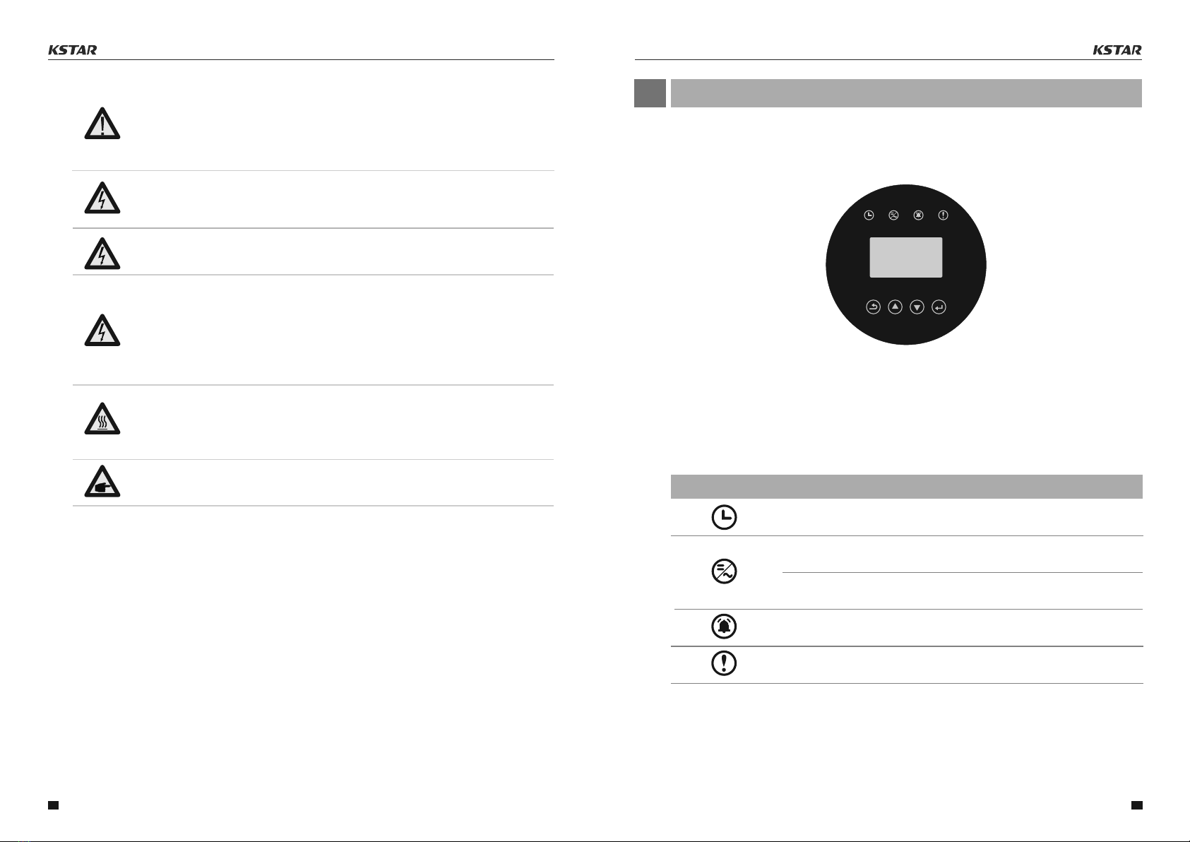
▲Table 3.1 status indicator
Checking: The device is checking.
ON
Generating: flashing indicates that the inverter is being
connected to the power grid.
WARNING:
To reduce the risk of fire, over-current protective devices (OCPD) are required for
circuits connected to the Inverter.
The DC OCPD shall be installed per local requirements. All photovoltaic source and
output circuit conductors shall have disconnects that comply with the NEC Article 690,
Part II.
CAUTION:
Risk of electric shock. Do not remove cover. There is no user serviceable parts inside.
Refer servicing to qualified and accredited service technicians.
CAUTION:
The PV array (Solar panels) supplies a DC voltage when they are exposed to sunlight.
CAUTION:
Risk of electric shock from energy stored in capacitors of the Inverter. Do not remove
cover for 5 minutes after disconnecting all power sources(service technician only).
Warranty may be voided if the cover is removed without unauthorized.
CAUTION:
The surface temperature of the inverter can reach up to 75°C (167 F).
To avoid risk of burns, do not touch the surface of the inverter while ifs operating.
Inverter must be installed out of the reach of children.
PV module used with inverter must have an IEC 61730 Class A rating.
1.Permanent installation is required.
2.The electrical installation must meet all the applicable regulations and standards.
3.The inverter must be installed according to the instructions stated in this manual.
4.The inverter must be installed according to the correct technical specifications.
2.3 Notice For Use
The inverter has been constructed according to the applicable safety and technical guidelines.
Use the inverter in installations that meet the following specifications ONLY:
5.To startup the inverter, the Grid Supply Main Switch (AC) must be switched on, before the
solar panel's DC isolator shall be switched on. To stop the inverter, the Grid Supply Main
Switch (AC) must be switched off before the solar panel's DC isolator shall be switched off.
If the equipment is used in a manner not specified by the manufacturer, the protection
provided by the equipment may be impaired.
User Manual User Manual
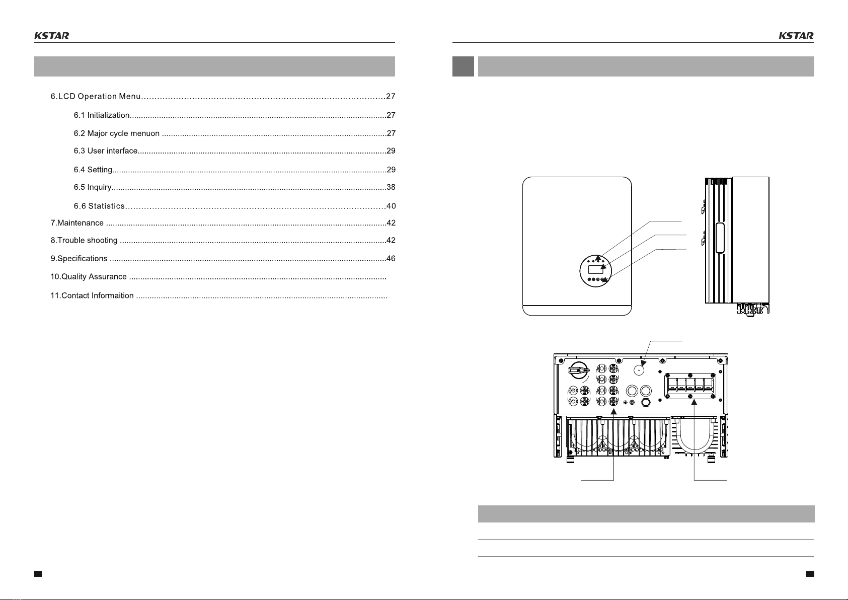
3.1 Front Panel Display
Over view
03
LCD display is Optional.
▲Figure 3.1 Front Panel Display
3.2 LED Status Indicator Light
The LED status indicator can display red and green. When the indicator light is on, it
indicates that there is power. When the indicator light is red, it indicates the alarm
state; when the indicator light is green, it indicates the operation state.
Light Status Description
twinkle
08 09
ON