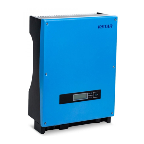
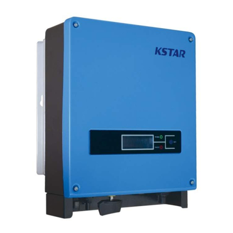
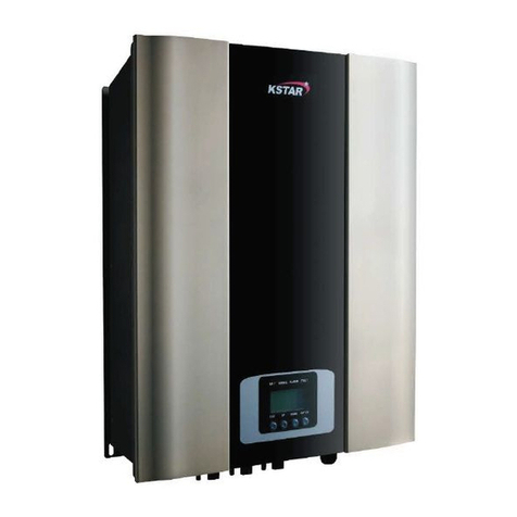
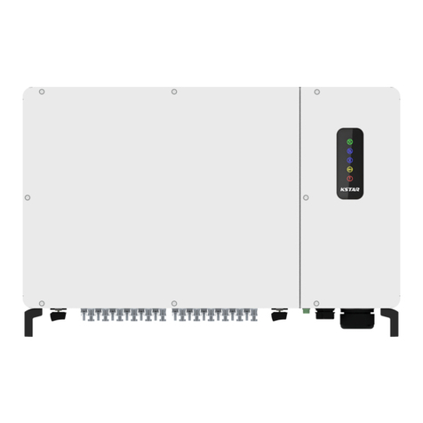
KStar KSG-12K User manual

KSG-12KKSG-12K
201611 Ver 1.0
Solar InverterSolar Inverter
User Manual

Installation and Operation Manual 1
Table of Contents
1. Introduction for Signs ....................................................................... 4
2. Introduction....................................................................................... 5
2.1 Preface ......................................................................................... 5
2.2 PV Grid-connected Generating System ...................................... 5
2.3 How to Use his Manual .............................................................6
3. Safety Instructions ............................................................................ 7
4. Overall Introduction.......................................................................... 8
4.1 Circuit Structure .......................................................................... 8
4.2 Description for External Interface............................................... 9
5. System Operation............................................................................ 10
5.1 System Mode............................................................................. 10
5.2 Grid-connected Operation ......................................................... 10
5.3 System Shutdown ...................................................................... 12
5.4 Error and Alarm......................................................................... 12
5.5 ype of system fault and trouble shooting ................................ 11
6. Human-machine Interface............................................................... 16
6.1 LCD controlled panel ................................................................ 16
6.2 Networking for monitoring ....................................................... 17
6.3 Dry contact................................................................................. 18
6.4 Remote control .......................................................................... 18
7. LCD Operation Menu ..................................................................... 19
7.1 Initialization .............................................................................. 19
7.2 Major cycle menu...................................................................... 19
7.3 User interface ............................................................................ 21
7.4 Setting ....................................................................................... 21
7.4.1 Input mode.......................................................................... 22
7.4.2 Standard for electric network ............................................. 22
7.4.3 Remote C RL..................................................................... 22

Installation and Operation Manual 2
7.4.4 Working parameters............................................................ 23
7.4.4.1 Starting-up voltage....................................................... 23
7.4.4.2 Starting-up timelag ...................................................... 23
7.4.4.3 Low voltage of electric network .................................. 24
7.4.4.4 High voltage of electric network ................................. 24
7.4.4.5 Low frequency of electric network................................24
7.4.4.6 High frequency of electric network..............................25
7.4.4.7 Please starting-up again ................................................25
7.4.5 485 address..........................................................................25
7.4.6 485 baudrate........................................................................26
7.4.7 485 protocol........................................................................26
7.4.8 Display language .................................................................26
7.4.9 LCD backlight..................................................................... 27
7.4.10 Date/time...........................................................................27
7.4.11 History clearing.................................................................27
7.4.12 Password setting................................................................28
7.4.13 Maintenance................................................................28
7.4.14 Factory Reset..............................................................28
7.5 Inquiry ........................................................................................29
7.5.1 INV MODEL.......................................................................29
7.5.2 MODEL SN.........................................................................29
7.5.3 Firmware..............................................................................30
7.5.4 RECORD.............................................................................30
7.6 Statistics .................................................................................... 31
7.6.1 ime statistics......................................................................31
7.6.2 imes of paralleling in.........................................................32
7.6.3 Power peak..........................................................................32
7.6.4 Generated energy of that day...............................................32
7.6.5 Generated energy of that week............................................32
7.6.6 Generated energy of that month..........................................33
7.6.7 Generated energy of that year..............................................33
Installation and Operation Manual 3
7.6.8 Gross generation..................................................................33
8. Installation ...................................................................................... 34
8.1 Overview ................................................................................... 34
8.2 Mechanical installation.............................................................. 35
8.2.1 Installation introductions.....................................................35
8.2.2 Mechanical dimension.........................................................35
8.2.3 Packing................................................................................36
8.2.4 Installation of Inverter.........................................................36
8.2.5 Installation Location............................................................37
8.2.6 Installation Procedure..........................................................37
8.2.7 Ambient requirement...........................................................38
8.3 Electric connection.................................................................... 39
8.3.1 Requirement for electric installation...................................39
8.3.2 Wire for alternating current connection...............................40
8.3.3 Wire for direct current connection.......................................40
8.3.4 Wire for communication connection...................................41
8.4 Starting and closing................................................................... 43
9. echnical Data ................................................................................ 44
10. Appendix ....................................................................................... 45
10.1 Quality assurance..................................................................... 45

Installation and Operation Manual 4
1. Introduction for Signs
In order to make a better use of this manual, please read the following
sign explanation carefully.
Warning!
his sign indicates that it may cause danger to safety of
users and/or attentions or instructions for possible serious
damage to hardware.
Instruction!
his sign indicates important attentions required for good
operation of the system.

Installation and Operation Manual 5
2. Introduction
2.1 Preface
Dear users, thank you for using photovoltaic grid-connected inverter
products manufactured by our company which is experienced in
development of photovoltaic grid-connected generating sets. We hope
this product can meet your demands and welcome you to put forward
more suggestions on performance and functions of this product.
2.2 PV Grid-connected Generating System
he photovoltaic grid-connected generating system is composed of
solar cell module, grid-connected inverter, metering devices and power
distribution system (as shown in Figure 1). he solar energy is
converted to DC electric power through solar cell module, which is
further converted to sine-wave current synchronous with grid
frequency and phase via grid-connected inverter. Such electric power is
then fed into power grid. he photovoltaic grid-connected inverter is
the key equipment in solar power system.
Figure 1: Application of Photovoltaic Grid-Connected Inverter in
Photovoltaic Generating System.

Installation and Operation Manual 6
2. How to Use This Manual
his manual aims to provide detailed product information and
installation & use instructions for users of KSG-12K photovoltaic
grid-connected inverter manufactured by this company. Please read
this manual carefully prior to use of this product and store it properly
in a place where it is convenient for installation, operation and
available for maintenance personnel.

Installation and Operation Manual 7
. Safety Instructions
﹡ Please read this manual carefully prior to installation. his
company assumes no responsibility for quality assurance upon
equipment damage due to installation failing to follow instructions
in this manual.
﹡ All operations and wiring shall be conducted by professional
electrical or mechanical engineer.
﹡ Do not move other parts inside the machine case except the
binding post during installation.
﹡ All electrical installations must conform to local standards for
electrical installation.
﹡ Please contact with local appointed personnel for system
installation and maintenance if this equipment requires the
maintenance.
﹡ Use of this equipment for grid-connected power generation must be
approved by local power supply departments.
﹡ When the photovoltaic array is installed in the day, it shall be
covered with lightproof materials; otherwise the array end will
subject to high voltage under exposure of sunlight, thus causing
personal risk.
Warning!
Ensure that the input DC voltage does not exceed 1000V
since higher input voltage may damage this equipment
permanently and causing other losses, under which
circumstance, this company assumes no responsibility for
quality assurance and joint responsibility.

Installation and Operation Manual 8
4. Overall Introduction
4.1 Circuit Structure
Figure 2 shows main circuit of KSG-12K inverter by which the direct
current is input via three-phase full-bridge circuit and transformed into
sine-wave current through filter and output to power grid. o make the
photovoltaic array generate in maximum power, the new type power
devices are adopted for this machine and the advanced MPP
algorithm is used at the DC side.
Figure 2: Main Circuit of KSG-12K Inverter

Installation and Operation Manual 9
4.2 Description for External Interface
Figure 3: Interface of KSG-12K Inverter
█
Instructions for Interface
﹡1: DC Input: DC input terminal, connected to positive and negative
electrode input of photovoltaic array respectively.
﹡2: Communication Interface RS232: connected with PC via joint
RS232.
﹡3: Communication Interface RS485: wire RS485A/B is connected
with PC via converter RS485/RS232. (When two or more
inverters are in parallel communication, 2P DIP switch beside
RJ45 of the last one should be “ON”. Or else, it may cause
communication interruption. hat 2P DIP switch is on, means
connecting a 120Ω communication terminal resistance between
the R/ + and R/ - )
﹡4: AC OU PU : AC output, spaced by three phases AC switch and
connected to L1, L2, L3, N and GND of three-phase grid. (3PH,
without “N”)
﹡5: DC switch: can judge the positive and negative electrode input
of photovoltaic array.
﹡6: Dry contact: interface (optional).

Installation and Operation Manual 10
5. System Operation
5.1 System Mode
he operation modes of KSG-12K grid-connected type inverter
include the initialization, waiting, self-checking, grid-connected
operating and error modes.
﹡ Initialization mode: the internal data will be initialized upon
power on of controller.
﹡ Waiting mode: the inverter will be under waiting mode if the
output voltage of PV battery board is low and it has not detected
any fault.
﹡ Self-checking mode: self-checking will be conducted by inverter
each time prior to grid-connected operation. he inspection items
include: inspection on insulation impedance at DC side, self-
checking for leakage current detection function and inspection on
AC output relay.
﹡ Grid-connected operating mode: the direct current of PV battery
board is converted to alternating current by the inverter for grid-
connected operation. he advanced MPP algorithm is adopted for
controller, making the inverter operating at the maximum power
point of PV arrays.
﹡ Error mode: the inverter will enter error mode when grid voltage/
frequency is abnormal or fault arises during grid-connected
process. At this time, it will stop transformation of electric energy
and cut away from the grid.
5.2 Grid-connected Operation
Prior to grid connection of the inverter, please confirm if the wirings
among input side of inverter, PV arrays, output side and power grid are
all correct. hree kinds of modes are optional for connection
between DC input side of KSG-12K grid-connected inverter and PV
arrays:

Installation and Operation Manual 11
﹡ Independent input mode: two groups of different PV arrays may be
connected to input end of inverter and independent MPP
controller is available for each group of PV arrays to control
grid-connected operation.
Figure 4: Independent Input Mode
﹡ Parallel input mode: only one group of PV arrays is connected
with input end of the inverter, which is then connected to input
side of inverter via two groups of parallel input terminals.
Figure 5: Parallel Input Mode
Users are required to set the item “Input Mode” under LCD
menu correctly based on actual conditions of
photovoltaic generating system and confirm that the mode of
connection at input side is consistent with setting (refer to
7.4.1).
If both input and output wirings are correct and the power grid is free of
abnormal conditions, the inverter will enter waiting mode. he grid
connection of inverter will be started fully automatic. After PV voltage
is higher than V
pv
, count down for grid connection will be started
automatically for controller and prepare for grid-connected operation
after delayed for
d
. Manual setting is available for both V
pv
and
d
through LCD panel.

Installation and Operation Manual 12
5. System Shutdown
If grid-connected power of inverter is smaller than 100W
continuously, the alarm of “zero power” will emerge. After alarming
for one minute, the inverter will cut away from the grid and reenter
waiting mode.
he inverter will cut away from the grid upon discovery of any
abnormal condition during the grid-connected process.
5.4 Error and Alarm
he error and alarm information of KSG-12K photovoltaic
grid-connected inverter refer to the following table:
Table 5.1 Working conditions and fault/alarm message
Working
conditions
Message
display
in
English
Description
Normal working
status
Inverter
OFF
No
display
PV voltage <180V, the inverter
i
s
switched off
Inverter
Stand-by
Stand-by
210V< PV voltage
<350V(adjustable)
Self-test
Checking
PV voltage
>350V(adjustable),
the
inverter get started and
self-test
all
modules
Normal Power
Generation
Normal
Generate AC power and feed
to
municipal
Grid after self-test
is completed
Monitoring parameter
display
Instant Power Rate &
Volume Of Power
Generated
XXXX W/
XXXXX Kwh
Instant power rate &
accumulated
power
generated
Voltage And Current
Of
PV1/PV2
Input
DC :XXX.X V
XXX.X A
Voltage and current from PV
arrays
Voltage And Current Of
AC
output
AC: XXX.X V
XXX.X A Grid Voltage and
current
System faulty
display
AC Voltage
Low
F00
AC Voltage is too
low
.
AC Voltage
High
F01
AC Voltage is too
high.
AC Frequency
Low
F02
AC frequency is too
low
.
AC Frequency
High
F03
AC frequency is too
high.

Installation and Operation Manual 13
Bus Voltage
Low
F04
Bus voltage is too
low
.
Bus Voltage
High
F05
Bus voltage is too
high.
Bus Voltage
Abnormal
F06
Positive voltage or negative
voltage
is too
high or too low on bus.
Insulation Impedance
Low
F07 PV arrays Insulation impedance
is
too
low
.
Input current
high
F08
PV Input current is too
high.
Reserved
F09
Reserved
Inverter Current
High
F10 Inverter current is too
high.
Inverter DC Current
High
F11 Inverter DC current is too
high.
Reserved
F12
Reserved
Heatsink emperature
High
F13 Heatsink temperature is too
High.
AC Relay
Abnormal
F14 AC relay is
abnormal.
PV Input Voltage
Low
F15 One of PV input is idle
when
inverter is
set on parallel
mode.
Remote
Off
F16 Status of inverter is on remote
off.
Reserved
F17
Reserved
SPI Communication
Fault
F18 Communication fault on
control
board.
Reserved
F19
Reserved
Leakage Current
High
F20 Leakage current is too
high.
Self-Checking Failure
Of
Leakage
Current
F21 Self-checking Failure of
Leakage
Current.
Consistency Voltage
Fault
F22 Inconsistent voltage
between
primary
CPU and secondary
CPU.
Consistency
Frequency
Fault
F23 Inconsistent frequency
between
primary
CPU and secondary
CPU.
DSP Operation
Fault
F24 DSP communication faulty
on
control
board.
DSP Communication
Lost
F32 DSP communication faulty
on
control
board.
Table 5.2 Alarm Information
Alarm message Alarm
code
Solutions
Zero Power W03 It is only a reminding message to show DC inputs
very low and inverter is about to shut down.
Clock Warning W16 Alarm message for clock
Lightning protection
device warning W21 Alarm message for Lightning protection device action

Installation and Operation Manual 14
5.5 Type of system fault and trouble shooting
Table 5. Type of system fault and trouble shooting
rouble Shooting
Alarm Message
Solution
System
Faulty
Or
Failure
ype
AC voltage &
frequency are too
high or too low
(F00-F03)
(1)Pease check mains voltage whether it is complied with local
safety standard.
(2)Please check the AC output line is properly connected. Make
sure its output voltage to see if it is normal.
(3)Disconnect PV input and restart the inverter and check whether
fault still exists.
(4)Contact with your local distributor if the fault still exists.
Bus voltage is too
high or too low
(F04-F05)
(1)Please check the setting of input mode.
(2)Disconnect PV input and restart the inverter and check whether
fault still exists.
(3)Contact with your local distributor if the fault still exists.
Bus Voltage
Abnormal
(F06)
(1)Please check the setting of input mode.
(2)Please try to restart inverter every few minutes for several times
and check whether fault still exists.
(3)Contact with your local distributor if the fault still exists.
Insulation impedance
Fault
(F07)
(1)Disconnect PV input and restart the inverter and check whether
fault still exists.
(2)Please measure impedance of PV+/PV- to ground whether is
over than 500KΩ.
(3)Please contact your local distributor if impedance is less than
500KΩ.
Input Current High
(F08)
(1)Please check the setting of input mode
(2)Disconnect PV input and restart the inverter and check whether
fault still exists.
(3)Contact with your local distributor if the fault still exists.
Hardware Current
High
(F09)
(1)Disconnect PV input and restart the inverter after few minutes
and check whether fault still exists.
(2)Contact with your local distributor if the fault still exists.
Inverter Current
High
(F10)
(1)Disconnect PV input and restart the inverter after few minutes
and check whether fault still exists.
(2)Contact with your local distributor if the fault still exists.
Inverter DC Current
high
(F11)
(1)Disconnect PV input and restart the inverter after few minutes
and check whether fault still exists.
(2)Contact with your local distributor if the fault still exists.

Installation and Operation Manual 15
Ambient
emperature High
(F12)
(1)Disconnect PV input and cool down the inverter then restart the
inverter to see if it is back to normal operation.
(2)Please check environmental temperature whether out of
working temperature.
(3)Contact with your local distributor if the fault still exists.
Heatsink
emperature High
(F13)
(1)Disconnect PV input and cool down the inverter then restart the
inverter to see if it is back to normal operation.
(2)Please check environmental temperature whether out of
working temperature.
(3)Contact with your local distributor if the fault still exists.
AC Relay Fault
(F14)
(1)Disconnect PV input and restart the inverter and check whether
fault still exists.
(2)Contact with your local distributor if the fault still exists.
PV Input Voltage
Low
(F15)
(1)Please check the configuration of PV input, one of PV input is
idle when inverter is set on parallel mode.
(2)Disconnect the PV input and restart the inverter and check
whether fault still exists.
(3)Contact with your local distributor if the fault still exists.
Remote Off
(F16)
he inverter is on remote OFF status, the Inverter can be turned
off/on remotely by monitoring software.
SPI communication
Fault
(F18)
(1)Disconnect PV input and restart the inverter and check whether
fault still exists.
(2)Contact with your local distributor if the fault still exists.
Leakage Current
High
(F20)
(1)Disconnect PV input and restart the inverter and check whether
fault still exists.
(2)Contact with your local distributor if the fault still exists.
Leakage Current
Self-Checking
Failure
(F21)
(1)Disconnect PV input and restart the inverter and check whether
fault still exists.
(2)Contact with your local distributor if the fault still exists.
Consistency Voltage
Fault
(F22)
(1)Disconnect PV input and restart the inverter and check whether
fault still exists.
(2)Contact with your local distributor if the fault still exists.
Consistency
Frequency Fault
(F23)
(1)Disconnect PV input and restart the inverter and check whether
fault still exists.
(2)Contact with your local distributor if the fault still exists.
DSP Operation Fault
(F24)
(1)Disconnect PV input and restart the inverter and check whether
fault still exists.
(2)Contact with your local distributor if the fault still exists.
DSP communication
Lost
(F32)
(1)Disconnect PV input and restart the inverter and check whether
fault still exists.
(2)Contact with your local distributor if the fault still exists.

Installation and Operation Manual 16
6. Human-machine Interface
6.1 LCD controlled panel
here are 4 buttons and 4 LEDs installed on the panel of
KSG-12K inverter, as shown in Figure 6.
Figure 6: LCD Controlled Panel
able 6.1 Description for LED light
LED light
Definition
W
AI
Indicator light for waiting of paralleling in
NORMAL
Indicator light for normal operation (generating electricity)
ALARM
Indicator light for warning alarm
F
A
U
L
Indicator light for error (fault)
able 6.2 Description for functions of buttons
Buttons
Functions
ESC
Return/Cancel/Exit
UP
Upwards choice menu/increase value when setting parameters
DOWN
Downwards choice menu/decrease value when setting parameters
EN ER
Enter menu/confirm
set value/move cursor
Note: press any button, backlight of LCD will last for a
certain period, specific time can be set in the menu.

Installation and Operation Manual 17
6.2 Networking for monitoring
he inverter is provided with various kinds of communication odes,
when the user requires to monitor the running information of
photovoltaic power generation system, we will offer the following
design scheme for monitoring system.
■ Intelligent cluster controller:
Figure 7: Data collector conducts monitoring through RS485
■ PC machine
Figure 8: PC machine conducts monitoring through RS485
■Data collector+ PC machine
Figure 9: Data collector and PC machine conduct monitoring
through RS485

Installation and Operation Manual 18
Signal Pins of Inverter RS485 terminal block are defined as
follow:
Figure 10: RS485 Port
6. Dry contact
Interface (optional).
6.4 Remote control
he inverter can realize the remote SHU DOWN and ON and power
limit regulatory function by the associated monitoring software.

Installation and Operation Manual 19
7. LCD Operation Menu
7.1 Initialization
Interface Explanation
During initialization…
please wait!
After starting-up of inverter, LCD will
firstly enter this interface, and deliver
parameters required by operation of the
machine to DSP.
7.2 Major cycle menu
After initialization, LCD will enter a major cycle menu to display
running information of the inverter in a circulating mode, including 10
interfaces for network voltage, frequency of electric network, etc. ime
for automatic switch-over between interfaces is 3 seconds, also the
interfaces can be switched manually by pressing UP or DOWN
buttons, if you want to fix at a certain interface, press EN ER to lock
this interface, after successful locking, a lock icon will occur at upper
right corner of this interface, press EN ER button again, this interface
will be unlocked, and the menu will continue to display in a circulating
mode.
Table of contents
Other KStar Inverter manuals

KStar
KStar KSG-3.2K-DM User manual

KStar
KStar KSH-3.68k-48 User manual

KStar
KStar KSG-15K User manual

KStar
KStar KSG-30K User manual

KStar
KStar KSG-32K User manual

KStar
KStar KSG-1.5K-SM User manual

KStar
KStar SOHO Series User manual

KStar
KStar KSG-10K User manual

KStar
KStar KSG-1K-SM User manual

KStar
KStar KSH-3.68k-48 User manual