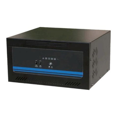
KStar KSH-3.68k-48 User manual

1
Contents
1Preface.......................................................................................1
2 Safety instructions................................................................................1
3Signs.........................................................................................2
4 System wiring diagram………………………………………………………………………. 2
5 Installation.............................................................................................3
5.1Packing list.................................................................3
5.2 Machine appearance............................................................................4
5.3 Installation position ....................................................................4
5.4 Inverter installation............................................................................5
5.5 Wiring.............................................................................6
5.5.1 AC wiring.........................................................................6
5.5.2 PV wiring......................................................................9
5.5.3 Battery connection.........................................................10
5.5.4 RS485 Communication connection....................................................12
5.5.5 RS232 and dry contact.....................................................13
5.5.6 External CT connection.....................................................13
6 Instructions for LED indicator ........................................................................15
7 Working mode....................................................................................16
7.1Self-generation and self-consumption ......................................................16
7.2Battery priority.............................................................................16
7.3Peak load shifting...........................................................................16
8 Display and setting.................................................................................18
9 Alarm code and error code..................................................................36
10Fault diagnosis and solutions............................................................37
11 Machine parameters………………………………………………………………………40
All manuals and user guides at all-guides.com
all-guides.com

1. P
r
T
h
b
atterie
general
Sol
a
transfor
m
AC to s
u
can be w
i
Stri
c
out-of-fa
c
supplier
f
O
u
offered
2. S
a
Bef
o
pro
f
Inst
a
Aft
e
b
us
Loc
To
e
b
att
Ma
k
oth
e
r
eface
h
is product is a
h
s as well as po
w
needs of custo
m
a
r energy can
m
ed into DC by
u
pport the load
o
i
sely manipula
t
c
t inspection
h
c
tory impertin
e
f
or better soluti
o
u
r company is
c
by the compan
y
a
fet
y
Ins
t
o
re using the i
n
f
essionals in ac
a
ll where child
r
e
r power-off, d
o
voltage is belo
al temperature
e
nsure full de-
e
eries and AC t
e
k
e sure DC inp
u
e
rwise, the inv
e
P
h
ybrid inverter,
w
er the load. It
i
m
ers and indus
t
produce dire
c
inverter to sup
p
o
r power grid.
B
t
ed and ratione
d
h
as been mad
e
e
nt to products.
o
n.
c
ommitted to t
h
y
is altered, no
t
t
ruction
s
n
verter, its ope
r
cordance with
l
r
en are not acc
e
o
not perform
m
w 36V.
of working in
v
e
nergization of
e
rminal need t
o
u
t voltage does
e
rter will be da
m
P
V panel
through which
i
s an intelligent
t
ry, and facilita
t
c
t current thro
u
p
ly batteries fo
r
B
esides, the p
o
d
based on prac
t
e
in terms of
If there is anyt
h
h
e constant im
p
t
imely notifica
t
s
r
ation and mai
n
l
ocally accepte
d
e
ssible.
m
aintenance wi
v
ertermay surp
a
inverter, DC s
w
o
be disconnect
e
not exceed th
e
m
aged. In this
c
Figure
1
PV inverter
solar energy c
a
energy produc
t
t
es personalize
d
u
gh PV pane
l
r
energy storag
e
o
rtion of energ
y
t
ical needs.
the manufact
u
h
ing missing, d
o
p
rovement of i
n
t
ion will be sen
t
n
tenance must
b
d
standards an
d
thin 5 minutes
;
a
ss 60 . Avoi
d
℃
w
itch should b
e
e
d.
e
maximum inp
u
c
ase, the comp
a
1
P
u
a
n be connecte
d
t
that incorpora
t
d
control.
l
s, partly of
w
e
, while partly
c
y
that is conver
t
u
ring, packagi
n
o
not hesitate t
o
n
verter, so if t
h
t
.
b
e performed b
y
d
regulations.
;
meanwhile,
m
d
touching lest
b
e
turned off, an
d
u
t voltage of t
h
a
ny does not as
s
u
blic power gri
d
d
and stored
i
t
es both
w
hich is th
e
c
onverted in
t
t
ed by invert
e
n
g as well
a
o
contact us
o
h
e informati
o
y
m
ake sure the
b
eing burnt.
d
PV termin
a
h
e inverter;
sume any
All manuals and user guides at all-guides.com

3. S
i
4.S
ys
B
p
ig
ns
Caution
-
Danger!
H
Hot
!
N
o
No dispos
a
This way
u
Overlayin
g
Fragile! H
CE sign
Guard aga
W
d
s
tem wir
i
B
attery
PV
p
anel
Igoring the sig
n
H
igh Voltage
!
E
o
touching
!
a
l as daily garb
a
u
p!
g
limit! Six lay
e
andle with care
inst damp
W
ait for 5 mi
n
d
ischarged.
i
n
g
dia
gr
Hybri
d
invert
e
n
s in the manua
E
lectric shock!
a
ge, but recycli
n
e
rs at most!
!
n
utes after po
w
r
am
d
e
r
l may cause mi
n
n
g through spe
c
w
e
r
-off and ma
k
n
or or moderat
e
c
ial means.
k
e sure the ma
P
o
L
o
g
e
injury.
chine is ful
l
o
wer
o
a
d
g
ri
d
All manuals and user guides at all-guides.com

5. Installation
5.1 Packing list
Prior to installation, please check if the outer appearance of machine is intact and the parts
i
attachment bag are not inconsistent with the list.
No. Name Quantit Description
1 Inverter 1 Power storage inverter
2 Installation pendants 1 Used for installing the inverter
3 Protective cover 2
Battery protective cover ,AC
protective cover and M4 mounting
screw ×8
4 Expansion tube 4
Used for fixing the installation
pendants
5 Self-tapping screw 4
Used for fixing the installation
pendants
6 Combined screw 2
Used for fixing the inverter on the
installation pendant
7 PV connection terminal 4
The PV input DC terminal, including
the positive and negative terminals
8 Wiring terminal 2 Wiring terminal of battery terminals
9 Slotted screwdriver 1 Used for removing PV connector
10 Battery screw 2 Battery wiring screw
Cd ilf li i i f
Figure 3
1 2 3 4 5
6 7 8 9 10
11 12 13 14 15
All manuals and user guides at all-guides.com

5.2Ma
c
5.3 In
Inv
e
the
m
lest
ope
r
1
1
4
1
c
hine appe
a
stallation
p
e
rter can be ins
t
m
achine, it is
a
it is affected b
y
r
ation life of th
3 User
m
4
Packi
n
5 Exter
n
1.LCD Displ
2.LED and b
u
3.Battery in
p
a
rance
p
osition
t
alled indoors
o
a
dvisable to ins
t
y
directsun rad
i
e inverter.
m
anual
n
g lis
t
n
al CT
ay
u
ttons
p
ut
4.
D
5.
P
6.
R
Ex
o
r outdoors .Gi
v
t
all the inverte
r
i
ation, rain, sn
o
1
1
1
Figure 4
D
C switch
P
V interface
R
S485/CAN (
B
ternal CT inter
f
v
en the coolin
g
r
in a well vent
i
o
w and others,
s
Providing user
s
installation, op
e
fault diagnosis a
n
Accessories list
Monitoring grid
B
MS)
f
ace
g
and water-pro
o
i
lated and shelt
e
s
o as to length
e
s
with guidance
e
ration, mainten
a
n
d the like.
current
7.RS232 inter
8. RS485/Wir
connection
9.Data input
p
10.AC interfa
c
o
f factors o
f
e
red place
e
n the
for
a
nce,
face
eless/ Intern
e
p
ort/ Dry co
n
c
e
All manuals and user guides at all-guides.com

The
Do
n
Inst
a
To
s
the
i
5.4 In
v
Pla
c
refe
in F
as p
inverter shoul
d
n
ot install the i
n
a
ll the inverter
s
ecure good h
e
i
nverter shoul
d
v
erter ins
t
c
e the pendant
i
r to Figure 8 f
o
igure 9 and us
e
ossible.
d
be installed v
n
verter on a fo
r
on a solid and
e
at dissipation
d
not
b
e smaller
t
allation
i
n the marked
d
o
r specific pen
d
e
Ø10 percussi
o
ertically or tilt
e
r
ward-leaning
o
ventilated surf
a
and easy dis
m
than the belo
w
d
rilling positio
n
d
ant dimension.
o
n drill as tool.
Figure 6
Figure
7
e
d no more tha
n
o
r horizontal pl
a
ce.
m
antlement, the
w
values.
n
on the wall o
f
Perforate in t
h
Drilling shoul
d
7
F
r
Lat
e
Bo
t
n
15°
ane.
minimum cle
a
f
selected area,
a
h
e drilling posit
i
d
be positioned
Top
r
ont
e
rals
t
tom
a
rance arou
n
a
nd please
i
on marked
as accuratel
All manuals and user guides at all-guides.com
all-guides.com

Purge away the dust inside and outside the drilling hole, and insert the expansion tube int
o
the hole vertically. Strike expansion tube directly with the hammer to make it fully into th
e
wall, then align the rack to the hole and tighten it with the self-tapping screw.
Gently hang the inverter onto the rack top-down, lock the setscrews flanking the inverter,
and make sure they are mounted correctly.
5.5 Wiring
5.5.1 AC Wirin
g
Figure 11
Figure 9
Figure10
All manuals and user guides at all-guides.com

con
fo
(2)The
imp
e
(3)Dis
c
(4)Lo
o
(5)Dis
a
(6)Pas
s
cov
e
(7)Wir
(8)
U
M
a
is
Ca
b
fo
rmity with th
e
PE line (grou
n
e
dance betwee
n
c
onnect the A
C
o
sen the nut.
a
ssemble the si
n
s
the cable suc
c
e
r and AC wiri
n
e stripping req
u
U
se tool to cla
m
a
ke sure that th
e
connected to the
b
le Singl
e
Nut
e
specification
o
n
d wire) of the
i
n
the neutrallin
e
C
circuit breake
r
n
gle-aperture s
c
essivelythrou
g
n
g terminal (as
u
irements
(
as
s
m
p the AC wirin
g
e
cable is free t
o
e
right
site of th
e
-aperture seal
i
Insulat
o
o
f grid connect
i
i
nverter must b
e
and ground w
r
between the i
n
ealing ring.
g
h the nut, sing
l
shown in Fig
u
s
hown in Figu
r
g
terminal and
w
o
pass through t
h
e inverter tighte
Figure
i
ng
o
r
Figure 1
2
i
on.
e reliably eart
h
ire is less than
n
verter and the
l
e-aperture seal
i
u
re 12
)
r
e 13
)
w
ire rod; screw
h
e waterproof c
o
en the nut
(
ref
11
AC Protective
O
2
No.
C
Le
n
h
ed so as to ens
u
10 Ω.
power grid.
i
ng ring, AC p
r
the nut, but do
o
mponents. On
c
fer to Figure 14
)
cover AC
W
O
uter diameter of wi
r
Description
C
ross-sectional area
o
conductor materials
n
gth of uninsulated
w
u
re the
r
otective
not tighten
i
c
e the termin
a
)
W
iring termi
n
r
ing
Va l u e
11~12
m
o
f
6mm
²
w
ire
About
All manuals and user guides at all-guides.com

(9)
C
w
i
sc
r
to
(10
)
C
onnect the A
C
i
th a screwdri
v
r
ewdriver or el
Figure 15
)
)
Tighten the
n
C
wiring termi
n
v
er or electric
ectric screwdri
v
n
ut.
n
al to the corres
screw driver (
s
v
er should be
4
Figure 14
Figure 1
5
ponding hole s
s
uggestion: st
e
4
mm and 8 ~ 1
2
5
ite of the inver
t
e
m diameters a
2
kg-f.cm respe
c
Clamped
t
er and lock
a
nd torsion
o
c
tively)
(
ref
e
Pan-head s
All manuals and user guides at all-guides.com

5.5
.
(1) Inst
a
(Termin
a
(2) Unt
a
(3) Aft
e
.
2 PV wir
i
a
llation instruc
a
ls are polarize
d
a
ngling the PV
e
r removing th
e
Figure 17
Figure 16
i
ng
tions for the c
o
d
,
please pay
a
wiring termin
a
e
PV connector
Figure 18
o
nnection of P
V
a
ttention to the
a
l
①
s
h
o
u
a
n
②
t
h
m
s
t
③
1
t
h
l
o
①
t
②
s
V
wiring termin
sign of “+” an
d
①
Recommen
h
ould be PV c
a
u
ter diameter
b
n
d Ø6mm resp
e
②
Insert the s
t
h
e spring with
y
m
ake sure the s
p
t
ep 2 in Figure
1
③
Butt conne
c
6).Tighten up
t
h
e fastening ri
n
o
ck it up.
①
Insert the
s
t
est pen into th
e
②
While with
d
s
crewdriver,pul
①
Loosen
fa
②
Pry the l
o
is shown in S
t
③
Pull out
o
connecting w
i
④
Pry the s
p
screwdriver a
n
al
d
“-” on the bo
d
ded PV input
c
a
ble with the in
n
b
eing 12AWG
(
e
ctively.
t
ripped cable,
a
y
our thumb or
p
p
ring is closed
(
1
6).
c
tors (refer to
F
t
he cable faste
n
n
g to the O-rin
g
s
lotted screwdri
v
e
position show
n
d
rawing the
l the connector
fa
steners of the
c
o
cking crank d
e
t
ep2 in the pict
u
o
f the ferrule o
f
i
re
p
ring open wit
h
n
d exit the cabl
e
d
y)
c
able: it
n
erand
(
4mm²)
a
nd press
p
liers to
(
refer to
F
igure
n
ers. Screw
g
, and then
v
er o
r
n
in the figu
r
outward
c
able
e
vice open a
s
u
re
f
the
h
a
e
All manuals and user guides at all-guides.com

5.5
.
Fo
r
sp
e
A
B
(1)
(2)
(3)
(4)
(5)Pa
b
a
t
.
3 Battery
A reverse po
l
connection.
D
warranty.
Be careful of
e
If the DC cir
c
may be gene
r
r
the safe oper
a
e
cifications.
Cros
s
Check if the
v
Disconnect th
Loosen the n
u
Disassemble
t
ss the cable su
c
t
tery protectiv
e
Si
n
Cable
connectio
l
arity connecti
o
D
amage caused
e
lectric shock
a
c
uit breaker be
r
ated in wiring.
a
tion of the sys
s
-sectional are
The length o
v
oltage of batte
r
e DC circuit b
r
u
t.
t
he single-aper
t
c
cessively thro
u
e
cover (refer t
o
Insul
a
n
gle-aperture sea
n
o
n may damag
by a reverse
a
nd chemical c
o
tween the inv
e
tem, it is advi
s
a of conducto
r
f uninsulated
w
r
ies complies
w
r
eaker between
t
ure sealing rin
g
u
gh the nut, si
n
o
Figure 19).
a
tor
ling ring
e the inverter.
polarity conn
e
o
ntamination.
e
rter and batter
i
s
able to use th
e
r
materials
w
ire
w
ith the produc
t
the inverter an
d
g
.
n
gle-aperture s
e
Please pay at
t
e
ction is not c
i
es is absent,
a
e
wire in line
w
20~25
m
About
1
t
specifications
d
batteries.
e
aling ring, ins
u
Battery
w
t
ention to t
h
overed und
e
a
n electric a
r
w
ith followi
n
mm
2
1
0mm
.
u
lator and
w
iring termin
a
All manuals and user guides at all-guides.com
all-guides.com

(
(
Hexagon-h
e
(
6)
Use tool t
o
do not tig
h
componen
t
to Figure
2
(
7)
Connect t
h
tighten it
50~70kg-
f
from the a
t
e
ad screw
o
clamp the bat
t
h
ten it. Make
s
t
s. Once the te
r
2
0
)
h
e Battery wiri
with a scr
e
f
.cm ), and the
n
t
tachment bag
+ ------R
e
Positive (Red)
t
ery wiring ter
m
s
ure that the c
a
r
minal is conne
c
ng terminal to
e
wdriver or
w
n
lock the bat
t
(
refer to Figur
e
d Cable
Pan-hea
Figure 2
m
inal and cabl
e
a
ble is free to
p
c
ted to the hol
e
the correspon
d
w
rench (sugg
e
t
ery protective
e 21
)
-
d screw
0
e
; and then scr
e
p
ass through t
h
e
site, tighten t
h
d
ing slot of th
e
e
stion: torsio
n
cover with pa
------Black
Negative (Bla
c
Clam
pe
e
w the nut,b
u
h
e waterpro
o
h
e nut.
(
ref
e
e
inverter a
n
n
should
b
n-head scre
w
c
k)
e
d
All manuals and user guides at all-guides.com

5.5.4 RS485 Communication connection
The power storage inverter contains two 485 interfaces, with one for external WiFi and
GPRS communication, and the otherfor lithium battery communication.
Please connect the RS-485 communication following the below steps:
(1)
Remove the water-proof components of RS-485 with screwdriver.
(2)
Loosen the nut.
(3)
Disassemble the single-aperture sealing ring.
(4)
Pass the cable successively through the nut, single-aperture sealing ring, insulator and she
e
metal parts.
(5)
Insert eight wire cores of the cable into the corresponding slot of crystal head (refer
t
Figure 23), and then clamp with tools.
(6)
Connect the crystal head that is clamped to RS-485 port in the inverter.
(7)
Attach the water-proof component of RS-485 to the inverter.
(8)
Tighten the nut.
1 2 3 4 5 6 7 8
A 485+ 485- Null CAN+ CAN- GNDS GNDS 5.0VS
B 485+ 485- Null Null GNDS GNDS 5.0VS 5.0VS
Figure 22
All manuals and user guides at all-guides.com

5.5
.
Power
The in
v
5.5.
6
(1) Di
s
.
5 RS232
a
storage inverte
r
v
erter has a DI
d
6
External
s
assembling th
e
A: RS485/C
A
a
nd dry c
o
r
has a 232 int
e
d
ata interface,
o
CT conne
c
e
wate
r
-proof c
o
C
a
RS-485 w
a
A
N (BMS)
o
ntact
e
rface, which is
o
n which key
7
c
tion
o
mponents of e
x
Sin
g
le-a
p
ert
u
a
ble
Nut
a
ter
p
roof com
po
Figure 2
RS232
Figure 24
used for prog
r
7
and 8 are sig
n
x
ternal CT
u
re sealin
g
rin
g
Insulator Sh
e
o
nents
3
r
am upgrading;
n
al input of dry
C
e
et metal parts
Dry conta
c
contact.
Cr
y
stal head
c
t
All manuals and user guides at all-guides.com

(2) Loo
(3) Pas
s
(4)Use
white c
screwd
r
sen the nut, an
d
s
the wire throu
g
a slotted screw
onnecting wire
r
iver, and make
Cable
d
untangle the s
i
g
h the waterpr
o
driver to keep
p
of external C
T
sure the conne
c
Singl
e
Nut
F
i
ngle-aperture
s
o
of components
p
ushing the lo
c
T
into the hole
c
tion is secure.
图25
e
-aperture seali
I
F
igure 26
Figure
2
s
ealing ring.
.
c
kwire groove
o
site of the left
Sh
e
ng ring
I
nsulato
r
2
7
o
f the terminal,
terminal; Loo
s
e
et metal parts
and insert t
h
s
en the slott
e
All manuals and user guides at all-guides.com

(5) Co
n
(6) Inst
a
(7)Ope
n
the card
s
6. I
n
I
P
o
n
nect the black
w
a
ll the water-pr
o
n
the connectio
n
s
lot of external
Note: E
x
n
structio
n
I iti li ti
o
wer grid line L
w
ire according
t
o
of component
,
n
port of extern
a
CT, and then b
u
x
ternal CT sh
o
n
s for L
E
HYBRY
D
(
Green
)
ff
t
o Step 4.
,
and tighten th
e
a
l CT; The arr
o
u
ckle it.
o
uld be place
d
E
D Indi
c
D
EPS
(Green
)
ff
Figure 28
Figure
2
e
wate
r
-proof s
h
o
w points to the
d
near the po
w
c
ator
ALAR
M
(Yellow
)
ff
2
9
h
eath nut.
power grid; Pl
a
w
er grid.
M
)
FAU
L
(Red
)
ff
a
ce the wire
i
L
T
)
All manuals and user guides at all-guides.com
all-guides.com

16
7. Working modes
The machine has three kinds of working modes: self-generation and self-consumption, battery
priority, and peak load shifting.
7.1 self-generation and self-consumption
When solar energy is sufficient, power converted by inverter (from solar energy) will first be
used to supply the load,with the residual for batteries and then the grid; If solar energy is
inadequate, power stored in batteries and PV energy will support the load altogether; as night
falls, batteries and mains supply will provide power for the load.
7.2 Battery priority
Power converted by inverter from solar energy will first be used to charge the battery, with the
residual power for the load.
7.3 Peak load shifting
The energy will be stored when the electricity price is low, which can be utilized when price
high; the timing control of machine charging and discharging may also be carried out based on
the actual usage.
7.4 Instructions for the use of three modes
(1) Before selecting the mode, you can set it up according to the local power grid, PV input
mode and battery type.
Power grid:
Stand-by off off off off
Hybrid power
connection on off off off
Off-network off on on off
Bypass of mains flash off on off
Fault off off off on
All manuals and user guides at all-guides.com

17
Note: If there are requirements for reactive power in the locality, please refer to 8.2.4 and set
up in line with the actual needs.
PV input mode:
Battery parameters:
(2) Select the corresponding mode based on actual situation
Self-generation and self-consumption(system default mode):
Select 1 to set up
Press ENTER button Enter password
Press ESC
button
Initial interface
before powering on
User
Default password 00000
Press UP/DOWN button
Press ENTER
button
Press ENTER
button
Choose according
to local power grid
Restart
3 Grid standards
Press ENTER
b
utton
Enterpassword 4 Operation
parameters
1 Reactive power mode
Setting
Press ENTER
button
Press ENTER
button
6 PV input
type
Enter password
1 System setting
Setting
Press ENTER
button Press ENTER button
Select the proper mode
based on the
requirements of
t
Press ENTER
button
Enter password Refer to menu 8.2.2and set
up according to actual
battery needs
2 Battery
parameters
Setting
Press ENTER
button
1 Working
mode
All manuals and user guides at all-guides.com

18
After the Restart interface appears, the machine will return to the selection interface of
three working modes;
If more items are to be set up, restart after finishing the setting.
Battery priority:
Note: When choosing battery priority mode, the corresponding charging current should
be opted for according to the battery type. The system default current is 20A.
Peak load shifting:
After finishing the setting of Peak load shifting mode,the charging and discharging time
also needto be set up.
Note:If the time is set up incorrectly, the system will pop up an interface indicating the setting
error. Charging and discharging time will return to the state prior to setting.
Press ENTER button
Enter password 1 System setting
Setting
Press ENTER
button Press ENTER button
Press ENTER button
Restart 1 Self-generation and
self-consumption
1 Working
mode
Press ENTER button
Enter password
Setting 1 System setting
Press ENTER
button
Press ENTER button
Press ENTER
b
utton 3 Battery priority
Restart
Press ENTER
button
Press ENTER
button
Enter
password
2 Peak load
shifting
1 Working
mode
1 System
setting
Setting
Press ENTER
button
Press ENTER button
Press ENTER
button
Refer to 8.2.1and
set up the time
according to
needs.
Restart
All manuals and user guides at all-guides.com

19
8. Display and Setting
8.1.1 PV1 input display interface
8.1.2 PV2 input display interface
8.1.3 Bus voltage
8.1. 4
Battery
8.1.5 Battery
Interface
Interface
Interface
Interface
Interface
PV1 INPUT
VOLT:33.8V
CURR:0.00A
POWER:0W
PV1 input real-time voltage
PV1 input real-time current
PV1 input power
PV2 INPUT
VOLT:49.8V
CURR:0.00A
POWER:0W
PV2 input real-time voltage
PV2 input real-time current
PV2 Input power
Bus voltage of the system
DCVOLTAGE
BUS:V
BATTERY
VOLT:42.2V
CURR:20.2A
Battery input voltage
Battery current (+ means discharge, - means
charge)
Battery type:(lead acid, lithium battery)
Battery temperature
Percentage of battery surplus capacity
BATTERY INFOR
TYPE:LEAD-ACID
TEMP:0.0℃
SOC:60%
All manuals and user guides at all-guides.com
Other manuals for KSH-3.68k-48
1
This manual suits for next models
2
Table of contents
Other KStar Inverter manuals

KStar
KStar KSG-12K User manual

KStar
KStar SOHO Series User manual

KStar
KStar KSH-3.68k-48 User manual

KStar
KStar KSG-3.2K-DM User manual

KStar
KStar KSG-15K User manual

KStar
KStar KSG Series User manual

KStar
KStar KSG-DM 10kW User manual

KStar
KStar KSG-1.5K-SM User manual

KStar
KStar KSG-3.2K-DM User manual

KStar
KStar KSG-120CL-M0/M3 User manual