KT INDUSTRIES MP 140 User manual

USER’S MANUAL
®
®
www.ktindustries.net
USER’S
MANUAL
®
®
MP 140 WELDER
ENGLISH
MODEL NO. 1-0140 MULTIPURPOSE
READ ALL PARTS OF USER’S MANUAL BEFORE INSTALLING OR OPERATING!

®
®
www.ktindustries.net
PAGE | PAGE | PÁGINA 2
page 3 WARNINGS
page 4 WELDING PREPERATION
page 5-6 CONTROLS/SPOOL SETUP
page 7-8 MIG WELDING
page 9 ARC WELDING
page 10 TIG WELDING
page 11-12 TROUBLE-SHOOTING
page 13 FRENCH
page 25 SPANISH
TECHNICAL SPECIFICATIONS
MP140
MIG STICK (MMA) TIG
Power Input 120V/60Hz 120V/60Hz 120V/60Hz
Rated Input Current 21A 21.3A 20.5A
Output Current Range 30-140A 30-75A 20-110A
Rated Duty Cycles 30% at 90A 40% at 75A 20% at 110A
Maximum OCV 86 VDC 86 VDC 86 VDC
Max Diameter .035 3/32” (2.38mm) 3/32” (2.38mm)
Efficiency 85%
Power Factor .7 Cos (θ)
Insulation Class F
Enclosure Protection IP 21S
Cooling Type Fan Cooled
Dimensions 21” x 9.3” x 16.9” (525 x 225 x 425mm)
Weight 34.5lbs (16kg)
SpEcificAtioNS

®
®
www.ktindustries.net
WARNiNgS
PAGE | PAGE | PÁGINA 3
PRODUCT WARRANTY
The manufacturer’s sole obligation under this warranty is limited to making replacement or repairs within 90 days of purchase. This warranty does not cover product malfunctions or damages
resulting from product tampering, misuse or abuse. Please follow the operating instructions carefully to maintain this warranty. Failure to do so will void the warranty. The manufacturer shall
also not be held liable for any indirect or consequential damages arising out of the use of this product. We shall in no event be liable for death, injuries to persons or property, or for incidental,
contingent, special or consequential damages arising from the use of our product. Please carefully maintain this warranty. This warranty is nontransferable and extends only to the original
buyer purchasing the products directly from authorized dealers. This warranty gives you specific legal rights and you may also have other rights which vary from state to state. A copy of the
original receipt is required as proof of purchase. To replace product under warranty, please return to place of purchase for an across-the-counter exchange.
! WARNING: READ ALL SAFETY WARNINGS AND INSTRUCTIONS
Do not remove warnings, nameplates, and labels on the machine. Never modify the plug in any way. Never remove grounding prong or use
ungrounded adapter plug. Avoid electric shock. Avoid bodily contact with grounded surfaces during use. Do not expose machine to rain or wet
conditions. Do not abuse the cord. Keep cord away from heat, oil, sharp edges, and/or moving parts. Keeps hands and fingers away from moving
parts, drive rolls, or fans. Do not drape cables over or around your body. Do not point MIG torch at any body part of yourself or others. Ensure
any extension cord used is at least 12 gauge, under 25’ length, and suitable for outdoor use. Do not use under the influence of drugs, alcohol, or
medication. Always wear eye and body protection. Arc rays and infrared raditation may injure eyes and burn skin. Always wear safety goggles
and protection featuring at least number 10 shade lens rating. Do not allow others to view without proper eye and body protection. Always wear
dry, insulated, fire and heat resistant gloves. Always use apron, cap, sleeves, and bibs designed and approved for welding procedures. Leather
leg protection with fire resistant shoes or boots should be worn while using machine. Do not wear pants with cuffs, shirts with open pockets, or
any clothing that can catch and hold molten metal or sparks. Wear flame resistant ear plugs or muffs to keep sparks out of ears. Always wear
dust mask or respirator. High pressure cylinders can explode if damaged, never expose cylinders to high heat, sparks, open flames, mechanical
shocks, or arcs. Do not touch or weld cylinder with MIG torch. Keep cylinders away from welding or electrical circuits. Always use proper
regulators, gas hoses, and fittings for the specific application. Keep flamable and explosive materials at least 10 meters from machine. Always
keep ABC fire extinguisher within reach. Do not leave machine unattended while plugged in. Do not use if power switch does not turn on or off.
Do not overreach and keep proper balance at all times. This product is not a toy, keep out of reach of children. Store securely and out of reach
of children, persons unfamiliar with machine, and untrained users. Avoid fumes and gases. Always keep your head out of the fumes. Do not
breath the fumes, use ventilation or exhaust to keep fumes and gases away from your breathing zone. Exposure to fumes can increase risk of:
cancer, Parkinson’s Disease, heart disease, ulcers, damage to reproductive organs, inflammation of intestines or stomach, kidney damage, and/
or respiratory diseases. Electromagnetic fields could cause pacemaker interference or failure. People with pacemakers should: avoid operating
alone, avoid electrical shock, use Ground Fault Circuit Interrupter (GFCI), and ensure power is properly grounded. Service by qualified technician
only. Disconnect from power source before making adjustments, changing accessories, or storing machine.
Use machine and accessories in accordance with these instructions and in manner intended for the machine, taking into account the working
conditions and the work to be performed. Use of machine for operations different from those intended could result in a hazardous situation.
! Warning: This product may expose you to chemicals such as lead, which is known to the State of California to cause cancer, birth defects, or
other reproductive harm. For information go to www.P65Warnings.ca.gov.
SAVE THIS MANUAL
KEEP SAFETY WARNINGS & PRECAUTIONS, SETUP, OPERATION, TROUBLE-SHOOTING, AND WARRANTY. READ THE
ENTIRE USER’S MANUAL INCLUDING ALL TEXT UNDER SUBHEADINGS BEFORE SETUP OR USE OF THIS PRODUCT.
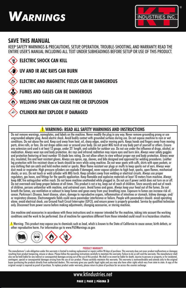
ELECTRIC SHOCK CAN KILL
UV AND IR ARC RAYS CAN BURN
ELECTRIC AND MAGNETIC FIELDS CAN BE DANGEROUS
FUMES AND GASES CAN BE DANGEROUS
WELDING SPARK CAN CAUSE FIRE OR EXPLOSION
CYLINDER MAY EXPLODE IF DAMAGED
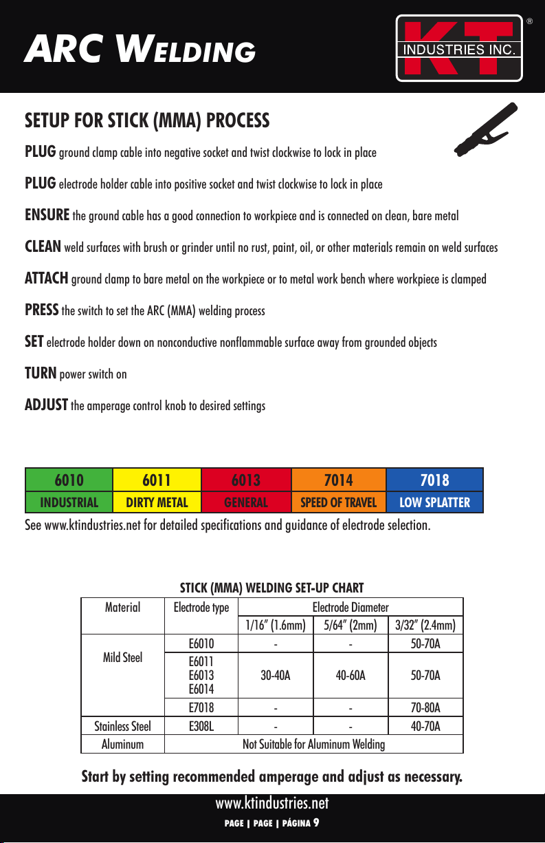
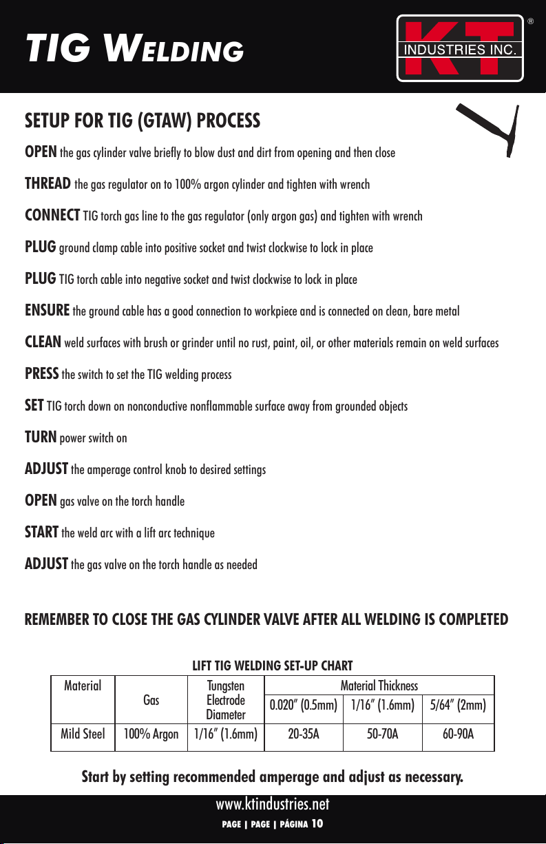
®
®
www.ktindustries.net
PAGE | PAGE | PÁGINA 4
WELdiNg pREpARAtioN
Clean & Bright Fire Extinguisher (ABC)
Keep Away From Flammable
Work Area Nearby Liquids, Gases, or Dusts
Auto-Darkening Hand & Body Breathing Protection
Welding Helmet Protection
Check for Misalignment, Ensure Switch is Plug into 15A
Binding, Breakage, or in the Off Position Grounded Circuit
Frayed Cords
Attach Ground Clamp to
Select
Bare Metal as Close to MIG/MMA/TIG
Work Piece as Possible
The warnings, precautions, and instructions discussed in this instruction manual cannot cover all possible conditions and
situations that may occur. It must be understood by the operator that common sense and caution are factors which cannot
be built into this product, but must be supplied by the operator.
PREPARE WORK AREA
PREPARE OPERATOR
PREPARE MACHINE
PREPARE WORK PIECE

®
®
www.ktindustries.net
coNtRoLS
PAGE | PAGE | PÁGINA 5
1. Power/Alarm/Work Indicator
2. MIG/MMA/TIG Switch
3. 2T/4T Switch
4. MIG Setting: Wire Speed Knob
MMA/TIG Setting: Amperage Knob
5. Voltage Knob
6. Inductance Knob
23
1
4 5
6
2T Mode: Squeeze and hold the trigger to weld. When ready to stop welding release the trigger.
4T Mode: Squeeze and release trigger to weld. When ready to stop welding squeeze and release trigger again.
BACK PANEL CONTROLS
1
1. Power Switch
2. Gas Input
3. Main Power Cable
2
3
FRONT PANEL CONTROLS
Machine controls may vary slightly.
Always consult a certified welding instructor and get proper training before operating.

®
®
www.ktindustries.net
coNtRoLS
PAGE | PAGE | PÁGINA 6
1. MIG Flux/Spool Gun Switch
2. Gas Quick Connect
3. Wire Spool (2 or 10lb)
4. Spool Knob
5. Feed Tensioner
6. Idler Arm
7. Wire Inlet Liner
8. Feed Roller Knob
9. Wire Feed Mechanism
2
3
1
45
6
78
9
INTERIOR CONTROLS
LOADING SPOOLS
LOOSEN feed tensioner knob to allow idler arm to swing up
CHECK feed roller for correct size and type groove to match wire size and type (flip or replace)
CUT off bent, crimped, or rusted wire to ensure no burrs, sharp edges, or contamination are present
HOLD tension on wire while guiding into feed guide (spool will unravel without tension)
ENSURE wire is threaded into groove of feed roller
CLOSE wire idler arm and rotate feed tensioner up
TIGHTEN feed tensioner as required (2-3 flux core, 3-5 solid wire)
FEED ROLLER SETUP
Fits 10lb
Spool
Fits 2lb
Spool
Included spool adaptor fits 2lb and 10lb wire spools
Wire diameter stamped
on each side
Solid Wire
Flux-Core Wire

®
®
www.ktindustries.net
Mig WELdiNg
PAGE | PAGE | PÁGINA 7
PLUG ground clamp cable into positive socket and twist clockwise to lock in place
PLUG wire feed cable into negative socket and twist clockwise to lock in place
CLEAN
weld surfaces with brush or grinder until no rust, paint, oil, or other materials remain on weld surfaces
ATTACH ground clamp to bare metal on the workpiece or to metal work bench where workpiece is clamped
PLUG machine into properly grounded GFCI protected receptical
PRESS the switch to set the MIG welding process
SET MIG torch down on nonconductive, nonflammable surface, away from grounded objects
TURN power switch on
ADJUST the wire speed, voltage, and inductance knobs to desired settings (see setup chart inside machine)
ENSURE correct diameter contact tip and nozzle are installed on torch
HOLD torch trigger until wire feeds through contact tip and extends 1/2” beyond nozzle
SETUP FOR GASLESS MIG (DCEN) PROCESS
Start by setting recommended amperage and adjust as necessary.
See setup chart inside machine cover.
FLUX CORED (DCEN)
GASLESS WIRES DC(-)
ER71-T-GS

®
®
www.ktindustries.net
Mig WELdiNg
PAGE | PAGE | PÁGINA 8
OPEN the shielding gas cylinder valve briefly to blow dust and dirt from opening and then close
THREAD the regulator on to cylinder and tighten with wrench
(use 580/320 adaptor if using C100 shielding gas)
CONNECT gas hose to the regulator outlet and to the welder inlet, then tighten with wrench
CONNECT wire feed gas hose inside the welder cover to the gas quick connect (quick connect collar should click)
PLUG ground clamp cable into negative socket and twist clockwise to lock in place
PLUG wire feed cable into positive socket and twist clockwise to lock in place
CLEAN weld surfaces with brush or grinder until no rust, paint, oil, or other materials remain on weld surfaces
ATTACH ground clamp to bare metal on the workpiece or to metal work bench where workpiece is clamped
PLUG machine into properly grounded GFCI protected receptical
PRESS the switch to set the MIG welding process
SET MIG torch down on nonconductive, nonflammable surface, away from grounded objects
TURN power switch on
ADJUST the wire speed, voltage, and inductance knobs to desired settings (see setup chart inside machine)
ENSURE correct diameter gas diffuser, contact tip, and gas nozzle are installed on torch
HOLD torch trigger until wire feeds through contact tip and extends 1/2” beyond nozzle
SETUP FOR SOLID WIRE MIG (DCEP) PROCESS
Start by setting recommended amperage and adjust as necessary.
See setup chart inside machine cover.
MIG WELDING (DCEP)
SOLID WIRES DC(+)
REMEMBER TO CLOSE THE GAS CYLINDER VALVE AFTER ALL WELDING IS COMPLETED
ER70S-6
FOLLOW SAME INSTRUCTIONS FOR SS 308/312 AND AL 4043/5356 WIRE

®
®
www.ktindustries.net
ARc WELdiNg
PAGE | PAGE | PÁGINA 9
STICK (MMA) WELDING SET-UP CHART
Material Electrode type Electrode Diameter
1/16” (1.6mm) 5/64” (2mm) 3/32” (2.4mm)
Mild Steel E6010 - - 50-70A
E6011
E6013
E6014 30-40A 40-60A 50-70A
E7018 - - 70-80A
Stainless Steel E308L - - 40-70A
Aluminum Not Suitable for Aluminum Welding
PLUG ground clamp cable into negative socket and twist clockwise to lock in place
PLUG electrode holder cable into positive socket and twist clockwise to lock in place
ENSURE the ground cable has a good connection to workpiece and is connected on clean, bare metal
CLEAN weld surfaces with brush or grinder until no rust, paint, oil, or other materials remain on weld surfaces
ATTACH ground clamp to bare metal on the workpiece or to metal work bench where workpiece is clamped
PRESS the switch to set the ARC (MMA) welding process
SET electrode holder down on nonconductive nonflammable surface away from grounded objects
TURN power switch on
ADJUST the amperage control knob to desired settings
6010 6011 6013 7014 7018
INDUSTRIAL DIRTY METAL GENERAL
SPEED OF TRAVEL
LOW SPLATTER
See www.ktindustries.net for detailed specifications and guidance of electrode selection.
SETUP FOR STICK (MMA) PROCESS
Start by setting recommended amperage and adjust as necessary.
ELECTRODE SELECTION

®
®
www.ktindustries.net
tig WELdiNg
PAGE | PAGE | PÁGINA 10
LIFT TIG WELDING SET-UP CHART
Material Gas Tungsten
Electrode
Diameter
Material Thickness
0.020” (0.5mm) 1/16” (1.6mm) 5/64” (2mm)
Mild Steel 100% Argon 1/16” (1.6mm) 20-35A 50-70A 60-90A
OPEN the gas cylinder valve briefly to blow dust and dirt from opening and then close
THREAD the gas regulator on to 100% argon cylinder and tighten with wrench
CONNECT TIG torch gas line to the gas regulator (only argon gas) and tighten with wrench
PLUG ground clamp cable into positive socket and twist clockwise to lock in place
PLUG TIG torch cable into negative socket and twist clockwise to lock in place
ENSURE the ground cable has a good connection to workpiece and is connected on clean, bare metal
CLEAN weld surfaces with brush or grinder until no rust, paint, oil, or other materials remain on weld surfaces
PRESS the switch to set the TIG welding process
SET TIG torch down on nonconductive nonflammable surface away from grounded objects
TURN power switch on
ADJUST the amperage control knob to desired settings
OPEN gas valve on the torch handle
START the weld arc with a lift arc technique
ADJUST the gas valve on the torch handle as needed
SETUP FOR TIG (GTAW) PROCESS
REMEMBER TO CLOSE THE GAS CYLINDER VALVE AFTER ALL WELDING IS COMPLETED
Start by setting recommended amperage and adjust as necessary.

®
®
www.ktindustries.net
tRoUbLE ShootiNg
COMMON PROBLEMS POSSIBLE CAUSES REMEDIES
YELLOW ALARM
INDICATOR IS ON 1.
Voltage is too high (>15%) or too low (<15%)
2. Bad ventilation leading to over-heat protection
3. Temperature is too high
4. Using over rated duty cycle
5. Machine is in incorrect mode
1. Switch off power source; check main supply;
restart welder when power recovers to normal state
2. Improve ventilation
3 & 4. Welder will recover when temperature cools
5.
Ensure MIG/MMA/TIG switch is in the correct mode
POWER IS ON BUT
DOES NOT LIGHT UP
WHEN SWITCHED ON
1. Power cable is not connected to outlet properly
2. Outlet has no power
3. Insufficient voltage or amperage
4. Plug does not have correct rating
1. Ensure proper connection at outlet & check voltage
2.
Ensure circuit has not been tripped before resetting
3. Check that circuit is designed for required voltage
and amperage according to specification
4. Ensure proper rating on plug
WIRE FEEDING MOTOR
ISN’T WORKING 1. Broken wire feed knob
2. Nozzle is blocked
3. Feed roller is loose
4. Incorrect wire feed roller size
5. Insufficient wire feed tension
6. Feed tensioner is too tight
1. Repair/replace by qualified technician
2. Change or clean nozzle
3. Tighten bolts
4. Change roller to correct size
5. Increase wire feed tension properly
6. Loosen feed tensioner to prevent continued
spinning after torch trigger is released
WIRE STOPS WHILE
WELDING 1. Torch cable is damaged and wire cannot feed
2. Torch liner is clogged, or too small for wire
3. Wire is tangled
4. Feed roller is not making enough contact
1. Straighten or replace torch cable
2.
Check for clog & correct sizing, replace if necessary
3. Check for cross winding or tangled spool
4. Check feed roller to ensure proper settings
WIRE BECOMES
TANGLED ON SPOOL
1. Excess wire feed tension
2. Incorrect size of contact tip
3. MIG torch not connected to wire feed mechanism
4. Damaged liner
1. Ensure correct pressure on wire feed
2.
Change to correct size contact tip according to wire
3. Reconnect MIG torch
4. Repair/replace by qualified technician
COOLING FAN NOT
WORKING OR TURNING
SLOW
1. Switch is broken
2. Fan is broken
3. Wire is broken or falling off
1. Replace switch by qualified technician
2. Replace or repair fan
3. Repair/replace by qualified technician
ARC IS NOT STABLE
AND SPATTER IS LARGE
1. Too large of contact tip makes current unsteady
2. Too thin of power cable
3. Too low of input voltage
4. Wire feeding resistance is too large
5. Incorrect wire feed speed
6. Loose connect of torch or ground cable
7. Insufficent or excess gas flow
8. Incorrect polarity
1. Change to correct size contact tip
2. Change power cable
3.
Enhance the input voltage
4. Untangle torch cable or replace the liner
5. Adjust wire feed speed
6. Ensure firm connections on machine
7. Set gas flow rate according to settings and ensure
tight connections
8. Ensure correct polarity for operation. DCEP for MIG,
DCEN for Flux Cored
WEAK ARC
1. Improper gauge or length of cable
2. Not enough current
1. Do not use extension cords
2. Adjust current according to metal thickness
Be CERTAIN to shut off the welder, disconnect it from power, and discharge to ground before
adjusting, cleaning, or repairing the unit.
PAGE | PAGE | PÁGINA 11

®
®
www.ktindustries.net
tRoUbLE ShootiNg
Be CERTAIN to shut off the welder, disconnect it from power, and discharge to ground before
adjusting, cleaning, or repairing the unit.
PAGE | PAGE | PÁGINA 12
THE MANUFACTURER AND/OR DISTRIBUTOR HAS PROVIDED THE PARTS LIST IN THIS MANUAL AS A REFERENCE TOOL ONLY
.
NEITHER THE MANUFACTURER OR
DISTRIBUTOR MAKES ANY REPRESENTATION OR WARRANTY OF ANY KIND TO THE BUYER THAT THEY ARE QUALIFIED TO MAKE ANY REPAIRS TO THE PRODUCT, OR THAT
THEY ARE QUALIFIED TO REPLACE ANY PARTS OF THE PRODUCT. IN FACT, THE MANUFACTURER AND/OR DISTRIBUTOR EXPRESSLY STATES THAT ALL REPAIRS AND PARTS
REPLACEMENTS SHOULD BE UNDERTAKEN BY CERTIFIED AND LICENSED TECHNICIANS, AND NOT THE BUYER. THE BUYER ASSUMES ALL RISK AND LIABILITY ARISING OUT
OF THEIR REPAIRS TO THE ORIGINAL PRODUCT OR REPLACEMENT PARTS THERETO, OR ARISING OUT OF THEIR INSTALLATION OF REPLACMENT PARTS THERETO.
NO ARC
1. Ground cable not connected properly
2. Worn, dirty, or incorrect size contact tip
1. Reconnect ground cable
2. Replace or clean contact tip
FLYING SPATTER
1. Work piece is too dirty, greasy, or rusty
1. Clean work piece
NO SHIELDING GAS
1. Torch is not connected properly
2. Gas hose is blocked or kinked
3. Interior rubber gas hose disconnected
1. Reconnect torch
2. Check gas system and gas line
3. Connect gas hose and ensure firm connection
POROSITY IN METAL
1. Shielding gas cylinder is empty
2. Insufficient or excess shielding gas
3. Work piece is dirty
4. Incorrect polarity
5. Contaminated or dirty wire
1. Check cylinder and refill if necessary
2. Check regulator for proper flow
3. Clean work piece
4. Ensure correct polarity for operation. DCEP for MIG,
DCEN for Flux Cored
5.
Ensure wire is clean and free of rust, replace if necessary
MODEL NO DESCRIPTION MODEL NO DESCRIPTION
2-1470 DRIVE ROLLER .023/.030 2-1482
SWAN NECK TORCH W/ DIFFUSER
2-1471 DRIVE ROLLER .030/.035 2-1483
MIG TORCH REPLACEMENT TRIGGER ASSEMBLY
2-1473
DRIVE ROLLER THREADED KNOB
2-1484
MIG TORCH HANDLE PLASTIC KNOB
2-1474
REPLACEMENT GAS HOSE
2-1485
MIG TORCH PLASTIC HANDLE
2-1475
OEM REGULATOR
2-1486
COMPLETE MIG TORCH HANDLE/LEAD
2-1476
MAIN PCB
2-1488
DOOR ASSEMBLY W/ HINGE, KNOB, SCREWS
2-1477
FRONT PANEL PCB
2-1489
TOP HANDLE ASSEMBLY
2-1478
CONTROL PCB
2-1522
FLUX CORE NOZZLE
2-1480
MALE MACHINE PLUG
2-1580
SPOOL ADAPTOR KIT (INCLUDES NUT & SPRING)
2-1481
REPLACEMENT GAS DIFFUSER
2-1581
POWER CORD ADAPTOR
K-T Industries, Inc.
3112 NW Blvd.
Sheldon, IA 51201
®
®
®
e
l
ect
!WARNING:
Electric Shock Can Kill. Do not touch electrical live parts or electrodes with skin or wet clothing. Always wear dry insulated gloves. Insulate yourself from work and ground.
Fumes and gases can injure you. Keep your head out of fumes. Use enough ventilation and/or exhaust at the arc to keep fumes and gases from your breathing area. Welding sparks can
cause fire or explosion. Keep flammable material away. Keep fire extinguisher nearby when welding. Arc rays can injure eyes and burn skin. Wear correct eye and body protection.
REPLACEMENT PARTS

USER’S MANUAL
®
®
www.ktindustries.net
UtiLiSAtEURS
MANUEL
®
®
MP140 SOUDEUR
FRANÇAIS
MODEL NO. 1-0140 POLYVALENT
LISEZ TOUTES LES PARTIES DU MANUEL DE L’UTILISATEUR AVANT L’INSTALLATION OU L’UTILISATION!

®
®
www.ktindustries.net
PAGE | PAGE | PÁGINA 14
page 1 ANGLAIS
page 15 AVERTISSEMENTS
page 16 PRÉPARATION AU SOUDAGE
page 17-18 COMMANDES/CONFIGURATION DE LA BOBINE
page 19-20 SOUDAGE MIG
page 21 SOUDAGE À L’ARC
page 22 SOUDAGE TIG
page 23-24 DÉPANNAGE
page 25 ESPAGNOL
SPÉCIFICATIONS TECHNIQUES
MP140
MIG BÂTON (MMA) TIG
Entrée de Puissance 120V/60Hz 120V/60Hz 120V/60Hz
Courant d’Entrée Nominal 21A 21.3A 20.5A
Plage de Courant de Sortie 30-140A 30-75A 20-110A
Cycle de service nominal 30% at 90A 40% at 75A 20% at 110A
OCV Maximale 86 VDC 86 VDC 86 VDC
Diamètre Maximum .035 3/32” (2.38mm) 3/32” (2.38mm)
Efficacité 85%
Facteur de puissance .7 Cos (θ)
Classe d’Isolation F
Protection de l’Enceinte IP 21S
Type de refroidissement Refroidi par Ventilateur
Dimensions 21” x 9.3” x 16.9” (525 x 225 x 425mm)
Lester 34.5lbs (16kg)
cARActéRiStiqUES

®
®
www.ktindustries.net
AvERtiSSEMENtS
PAGE | PAGE | PÁGINA 15
GARANTIE DU PRODUIT
La seule obligation du fabricant en vertu de cette garantie se limite à effectuer le remplacement ou les réparations dans les 90 jours suivant l’achat. Cette garantie ne couvre pas les dysfonctionnements du produit
ou les dommages résultant d’une altération, d’une mauvaise utilisation ou d’un abus du produit. Veuillez suivre attentivement les instructions d’utilisation pour conserver cette garantie. Ne pas le faire annulera la
garantie. Le fabricant décline également toute responsabilité en cas de dommages indirects ou consécutifs résultant de l’utilisation de ce produit. Nous ne serons en aucun cas responsables des décès, des blessures
aux personnes ou des biens, ou des dommages accessoires, contingents, spéciaux ou consécutifs résultant de l’utilisation de notre produit. Veuillez conserver soigneusement cette garantie. Cette garantie n’est pas
transférable et s’étend uniquement à l’acheteur d’origine qui achète les produits directement auprès de revendeurs agréés. Cette garantie vous donne des droits légaux spécifiques et vous pouvez également avoir
d’autres droits qui varient d’un état à l’autre. Une copie du reçu original est requise comme preuve d’achat. Pour remplacer un produit sous garantie, veuillez retourner au lieu d’achat pour un échange au comptoir.
! AVERTISSEMENT : LISEZ TOUS LES AVERTISSEMENTS ET INSTRUCTIONS DE SÉCURITÉ
Ne retirez pas les avertissements, les plaques signalétiques et les étiquettes de la machine. Ne modifiez jamais la fiche de quelque manière que ce soit. Ne retirez jamais la broche
de mise à la terre ou n’utilisez jamais une prise d’adaptateur non mise à la terre. Évitez les chocs électriques. Évitez tout contact corporel avec des surfaces mises à la terre pendant
l’utilisation. N’exposez pas la machine à la pluie ou à des conditions humides. N’abusez pas le cordon. Gardez le cordon à l’écart de la chaleur, de l’huile, des arêtes vives et/ou
des pièces mobiles. Maintient les mains et les doigts à l’écart des pièces mobiles, des rouleaux d’entraînement ou des ventilateurs. Ne placez pas les câbles sur ou autour de votre
corps. Ne dirigez pas la torche MIG vers une partie de votre corps ou celle d’autres personnes. Assurez-vous que toute rallonge utilisée est d’au moins un calibre 12, d’une longueur
inférieure à 7 mètres et adaptée à une utilisation en extérieur. Ne pas utiliser sous l’influence de drogues, d’alcool ou de médicaments. Portez toujours une protection pour les yeux
et le corps. Les rayons d’arc et les rayonnements infrarouges peuvent blesser les yeux et brûler la peau. Portez toujours des lunettes de sécurité et une protection avec au moins un
indice de verre de teinte 10. Ne permettez pas aux autres de voir sans une protection adéquate des yeux et du corps. Portez toujours des gants secs, isolants, résistants au feu et à
la chaleur. Utilisez toujours un tablier, une casquette, des manches et des bavoirs conçus et approuvés pour les procédures de soudage. Une protection des jambes en cuir avec des
chaussures ou des bottes résistantes au feu doit être portée lors de l’utilisation de la machine. Ne portez pas de pantalons avec des revers, des chemises avec des poches ouvertes
ou des vêtements qui peuvent attraper et retenir du métal en fusion ou des étincelles. Portez des bouchons d’oreille ou des protège-oreilles résistants aux flammes pour empêcher
les étincelles d’atteindre les oreilles. Portez toujours un masque anti-poussière ou un respirateur. Les cylindres à haute pression peuvent exploser s’ils sont endommagés, ne jamais
exposer les cylindres à une chaleur élevée, des étincelles, des flammes nues, des chocs mécaniques ou des arcs. Ne pas toucher ou souder le cylindre avec la torche MIG. Tenir les
bouteilles éloignées des soudures ou des circuits électriques. Utilisez toujours des régulateurs, des tuyaux de gaz et des raccords appropriés pour l’application spécifique. Gardez
les matériaux inflammables et explosifs à au moins 10 mètres de la machine. Gardez toujours l’extincteur ABC à portée de main. Ne laissez pas la machine sans surveillance
lorsqu’elle est branchée. Ne pas utiliser si l’interrupteur d’alimentation ne s’allume pas ou ne s’éteint pas. Ne vous allongez pas trop et gardez un bon équilibre à tout moment.
Ce produit n’est pas un jouet, tenir hors de portée des enfants. Stockez en toute sécurité et hors de portée des enfants, des personnes non familiarisées avec la machine et des
utilisateurs non formés. Éviter les fumées et les gaz. Gardez toujours la tête hors des fumées. Ne respirez pas les fumées, utilisez la ventilation ou l’échappement pour éloigner les
fumées et les gaz de votre zone respiratoire. L’exposition aux fumées peut augmenter le risque de : cancer, maladie de Parkinson, maladie cardiaque, ulcères, lésions des organes
reproducteurs, inflammation des intestins ou de l’estomac, lésions rénales et/ou maladies respiratoires. Les champs électromagnétiques peuvent provoquer des interférences ou
une défaillance du stimulateur cardiaque. Les personnes portant un stimulateur cardiaque doivent : éviter d’opérer seules, éviter les chocs électriques, utiliser un disjoncteur de fuite
à la terre (GFCI) et s’assurer que l’alimentation est correctement mise à la terre. Entretien par un technicien qualifié uniquement. Débranchez de la source d’alimentation avant
d’effectuer des réglages, de changer d’accessoires ou de ranger la machine.
Utilisez la machine et les accessoires conformément à ces instructions et de la manière prévue pour la machine, en tenant compte des conditions de travail et du travail à effectuer.
L’utilisation de la machine pour des opérations différentes de celles prévues peut entraîner une situation dangereuse.
! Avertissement: Ce produit peut vous exposer à des produits chimiques tels que le plomb, reconnu par l’État de Californie comme pouvant causer le cancer, des malformations
congénitales ou d’autres troubles de la reproduction. Pour plus d’informations, rendez-vous sur www.P65Warnings.ca.gov.
CONSERVEZ CE MANUEL
CONSERVEZ LES AVERTISSEMENTS ET PRÉCAUTIONS DE SÉCURITÉ, LA CONFIGURATION, LE FONCTIONNEMENT, LE DÉPANNAGE ET LA GARANTIE. LISEZ
L’INTÉGRALITÉ DU MANUEL DE L’UTILISATEUR, Y COMPRIS TOUT LE TEXTE DES SOUS-TITRES, AVANT D’INSTALLER OU D’UTILISER CE PRODUIT.
UN CHOC ÉLECTRIQUE PEUT TUER
LES RAYONS UV ET IR ARC PEUVENT BRÛLER
LES CHAMPS ÉLECTRIQUES ET MAGNÉTIQUES PEUVENT ÊTRE DANGEREUX
LES FUMÉES ET LES GAZ PEUVENT ÊTRE DANGEREUX
L’ÉTINCELLE DE SOUDAGE PEUT PROVOQUER UN INCENDIE OU UNE EXPLOSION
LE CYLINDRE PEUT EXPLOSER S’IL EST ENDOMMAGÉ

®
®
www.ktindustries.net
PAGE | PAGE | PÁGINA 16
pRépARAtioN AU SoUdAgE
Espace de travail Extincteur (ABC) Tenir à l’écart des liquides,
propre et lumineux à proximité
gaz ou poussières inflammables
Casque de Protection des Protection respiratoire
Soudage mains et du corps
Vérifiez le désalignement,
Assurez-vous que Branchez-le sur un
la reliure, la rupture ou
l’interrupteur est en circuit de mise à la
les cordons effilochés position d’arrêt terre de 15 A
Fixez la pince au métal
Sélectionnez
nu aussi près que possible
MIG/MMA/TIG
de la pièce à usiner
Les avertissements, précautions et instructions abordés dans ce manuel d’instructions ne peuvent pas couvrir toutes les
conditions et situations possibles qui peuvent se produire. L’opérateur doit comprendre que le bon sens et la prudence sont
des facteurs qui ne peuvent être intégré à ce produit, mais doit être fourni par l’opérateur.
PRÉPARER LA ZONE DE TRAVAIL
PRÉPARER L’OPÉRATEUR
PRÉPARER LA MACHINE
PRÉPARER LA PIÈCE À USINER

®
®
www.ktindustries.net
LES coNtRôLES
PAGE | PAGE | PÁGINA 17
1. Indicateur d’alimentation/alarme/travail
2. Commutateur MIG/MMA/TIG
3. Commutateur 2T/4T
4. Réglage MIG : Bouton de vitesse de fil
Réglage MMA/TIG : Bouton d’intensité
5. Bouton de tension
6. Bouton d’inductance
23
1
4 5
6
Mode 2T:
Pressez et maintenez la gâchette pour souder, lorsque vous êtes prêt à arrêter de souder, relâchez la gâchette.
Mode 4T:
Appuyez et relâchez la gâchette pour souder, lorsque vous êtes prêt à arrêter, appuyez et relâchez à nouveau la gâchette.
COMMANDES DU PANNEAU ARRIÈRE
1
1. Interrupteur
2. Entrée de gaz
3. Câble d’alimentation principal
2
3
COMMANDES DU PANNEAU AVANT
Les commandes de la machine peuvent varier légèrement. Consultez toujours un
instructeur de soudage certifié et obtenez une formation appropriée avant d’utiliser.

®
®
www.ktindustries.net
LES coNtRôLES
PAGE | PAGE | PÁGINA 18
1.
Commutateur de torche à flux/bobine MIG
2. Connexion rapide au gaz
3. Bobine de fil
4. Bouton de bobine
5. Tendeur d’alimentation
6. Bras de renvoi
7. Doublure d’entrée de fil
8. Bouton du rouleau d’alimentation
9. Mécanisme d’alimentation en fil
2
3
1
45
6
78
9
COMMANDES INTÉRIEURES
CHARGEMENT DES BOBINES
DESSERREZ le bouton du tendeur d’alimentation pour permettre au bras de renvoi de se relever
VÉRIFIEZ
que la taille et le type de rainure du rouleau d’alimentation correspondent à la taille/au type de fil (retournez ou remplacez)
COUPEZ le fil plié, serti ou rouillé pour vous assurer qu’il n’y a pas de bavures, d’arêtes vives ou de contamination
MAINTENEZ
la tension sur le fil tout en le guidant dans le guide d’alimentation (la bobine se déroulera sans tension)
ASSUREZ-VOUS que le fil est enfilé dans la rainure du rouleau d’alimentation
FERMER le bras tendeur de fil et tourner le tendeur d’alimentation vers le haut
SERREZ le tendeur d’alimentation au besoin (noyau de flux 2-3, fil solide 3-5)
CONFIGURATION DU ROULEAU D’ALIMENTATION
Convient
à 10 lb
Bobine
Convient
à 2 lb
Bobine
L’adaptateur de bobine inclus convient aux bobines de fil de 2 et 10 lb
Diamètre du fil estampé
de chaque côté
Fil solide
Fil à noyau de flux

®
®
www.ktindustries.net
SoUdAgE Mig
PAGE | PAGE | PÁGINA 19
BRANCHEZ
le câble de la pince de masse dans le positif et tournez dans le sens des aiguilles d’une montre pour le verrouiller
BRANCHEZ
le câble d’alimentation du fil dans le négatif et tournez dans le sens des aiguilles d’une montre pour le verrouiller
NETTOYEZ
les surfaces de soudure jusqu’à ce qu’il ne reste plus de rouille, de peinture, d’huile ou d’autres matériaux
FIXEZ la pince de mise à la terre sur le métal nu de la pièce ou sur l’établi en métal où la pièce est serrée
BRANCHEZ
la machine dans une prise correctement mise à la terre et protégée par un disjoncteur de fuite à la terre
APPUYEZ sur l’interrupteur pour régler le processus de soudage MIG
DÉPOSER
la torche MIG sur une surface non conductrice ininflammable loin des objets mis à la terre
ALLUMEZ l’interrupteur d’alimentation
AJUSTEZ
la vitesse du fil, la tension et l’inductance aux paramètres souhaités (voir le tableau de configuration à l’intérieur de la machine)
ASSUREZ-VOUS que la pointe de contact et la buse de diamètre correct sont installées sur la torche
MAINTENIR
la gâchette de la torche jusqu’à ce que le fil passe à travers la pointe de contact et s’étende de 12 mm au-delà de la buse
PROCÉDÉ MIG SANS GAZ (DCEN)
Commencez par régler l’ampérage recommandé et ajustez si nécessaire.
Voir le tableau de configuration à l’intérieur du capot de la machine.
ER71-T-GS
FIL FOURRÉ (DCEN)
FILS SANS GAZ DC(-)

®
®
www.ktindustries.net
SoUdAgE Mig
PAGE | PAGE | PÁGINA 20
OUVREZ
brièvement la valve de la bouteille de gaz de protection pour chasser la poussière et la saleté de l’ouverture, puis fermez-la
VISSER le régulateur sur le cylindre et serrer avec une clé
(utilisez un adaptateur 580/320 si vous utilisez un gaz de protection C100)
CONNECTER
le tuyau de gaz à la sortie du régulateur et à l’entrée de la soudeuse, puis serrer avec une clé
CONNECTER
le tuyau de gaz d’alimentation en fil à l’intérieur du couvercle de la soudeuse au raccord rapide de gaz
BRANCHEZ
le câble de la pince de masse dans le négatif et tournez dans le sens des aiguilles d’une montre pour le verrouiller
BRANCHEZ
le câble d’alimentation du fil dans le positif et tournez dans le sens des aiguilles d’une montre pour le verrouiller
NETTOYEZ les surfaces de soudure jusqu’à ce qu’il ne reste plus de rouille, de peinture, d’huile ou d’autres matériaux
FIXEZ la pince de mise à la terre sur le métal nu de la pièce ou sur l’établi en métal où la pièce est serrée
BRANCHEZ
la machine dans une prise correctement mise à la terre et protégée par un disjoncteur de fuite à la terre
APPUYEZ sur l’interrupteur pour régler le processus de soudage MIG
DÉPOSER
la torche MIG sur une surface non conductrice ininflammable loin des objets mis à la terre
ALLUMEZ l’interrupteur d’alimentation
AJUSTEZ
la vitesse du fil, la tension et l’inductance aux paramètres souhaités (voir le tableau de configuration à l’intérieur de la machine)
ASSUREZ-VOUS
que le diffuseur de gaz, le tube contact et la buse de gaz de diamètre correct sont installés sur la torche
MAINTENIR
la gâchette de la torche jusqu’à ce que le fil passe à travers la pointe de contact et s’étende de 12 mm au-delà de la buse
PROCÉDÉ MIG À FIL PLEIN (DCEP)
Commencez par régler l’ampérage recommandé et ajustez si nécessaire.
Voir le tableau de configuration à l’intérieur du capot de la machine.
MIG WELDING (DCEP)
SOLID WIRES DC(+)
N’OUBLIEZ PAS DE FERMER LE ROBINET DE LA BOUTEILLE DE GAZ UNE FOIS TOUTES LES SOUDURES TERMINÉES
ER70S-6
SUIVEZ LES MÊMES INSTRUCTIONS POUR LES FILS SS 308/312 ET AL 4043/5356
Table of contents
Languages:
Other KT INDUSTRIES Welding System manuals
Popular Welding System manuals by other brands

Air Liquide
Air Liquide MAJOR 251S Safety instruction for use and maintenance

BOC
BOC Smootharc TIG 185 DC Service manual

Sealey
Sealey Power WELDERS TIG170T instructions

Thermal Dynamics
Thermal Dynamics CUTSKILL C-100A Operation manual

EINHELL
EINHELL BT-IW 160 operating instructions

Nu-Tec Systems
Nu-Tec Systems TG200 instruction manual