Table of Contents
1. Introduction
1.1AdapterFeatures ................................................................ 1
1.2ConnectorandLEDs ........................................................... 2
2. Installing the Adapter
2.1Installingthe Adapter .......................................................... 3
2.2Connectingto theNetwork .................................................. 4
3. Network Driver Installation
3.1DriverInformation................................................................. 7
3.2 PCI BIOS Setup .................................................................. 8
4. Setup Program and Diagnostics
4.1Running Setup Program ...................................................... 9
4.2 Functions on the Main Menu............................................. 12
5. LED Indicators
5.1Interpretations ................................................................... 17
Appendix
A.1Specifications ................................................................... 18
A.2RJ-45Connectors&Cable ............................................... 19
A.3Auto-negotiationFunction................................................. 20
A.4DiagnosticsReport ........................................................... 21
A.5Installing Remote BootROM ............................................ 22
Figures
Figure1-1 Network Connector and LEDs .................................. 2
Figure 2-1 Inserting the Adapter into the PCI Slot ..................... 4
Figure2-2NetworkConnector................................................... 4
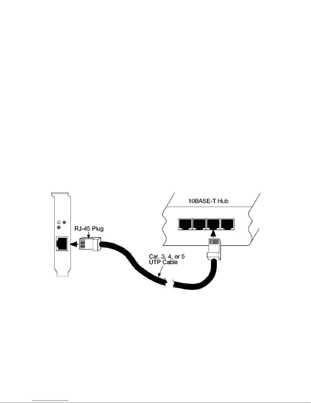
Figure2-3 Connecting10BASE-TCable ................................... 5
Figure2-4Connecting100BASE-TXCable ............................... 6
Figure4-1Main Menu of theSetup Program............................. 9
Figure4-2AdapterInformation ................................................. 11
Figure4-3 DOS ODIDriverInstallationWindow....................... 12
Figure4-4Setup Menu............................................................ 13
Figure4-5DiagnosticsMenu .................................................. 14
FigureA-1RJ-45ConnectorPinAssignments ........................ 19