KTM TROXLER TV 2000 User manual

Document:BA-TV2000-2003-07.doc
Screw capping machine TV 2000
KTM-TROXLER
Wine cellar machines – Stainless steel technology
In der Rohrmatt 8
77955 Ettenheim - Münchweier
Tel. 07822/446940-0
Fax. 07822/446940-25
e-mail : info@ktm-troxler.de
Internet :www.ktm-troxler.de

Declaration of conformity
Contents
1. For your safety ...................................................................................... 3
Symbols used in these instructions .................................................................... 3
Warning signs on the screw capping machine ................................................... 3
During emergencies ........................................................................................... 3
Safe working environment.................................................................................. 3
Stability of the plant ............................................................................................ 3
Safety devices .................................................................................................... 4
Intended use....................................................................................................... 4
For the environment ........................................................................................... 4
Safe transportation ............................................................................................. 4
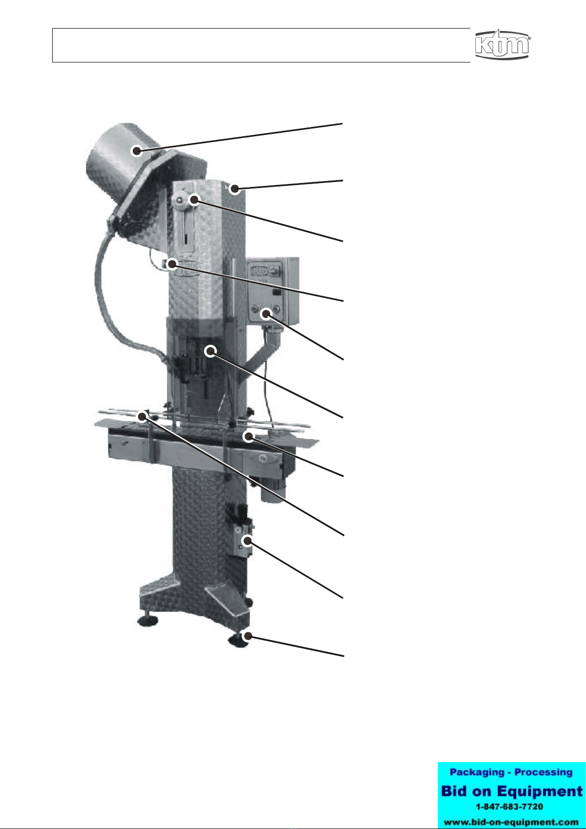
2. Overview of screw capping machine.................................................. 5
3. Operator controls on switching unit................................................... 6
4. Adjusting the TV 2000............................................................................ 7
Preparing the capping unit.................................................................................. 7
Sterilising the screw capping machine................................................................ 7
Adjusting the bottle cap feeder to the bottle height............................................. 8
Adjusting the bottle guide to the bottle diameter................................................. 8
Assembling the capping unit............................................................................... 9
Dismantling the screw cap separator prior to transportation............................. 10
5. Technical Data..................................................................................... 11
6. Maintenance and Care........................................................................ 12
After the work has been completed .................................................................. 12
7. Assistance in case of malfunctions .................................................. 13
Troubleshooting instructions............................................................................. 13
Fault table......................................................................................................... 13
8. Accessories ......................................................................................... 14
9. Appendix.............................................................................................. 14
Parameter change for Siemens LOGO!........Fehler! Textmarke nicht definiert.
Circuit diagram for electricians .....................Fehler! Textmarke nicht definiert.
EU declaration of conformity..................................................................... 15

Declaration of conformity
About these operating instructions
This document
• explains how to safely operate and adjust the machine
• indicates any hazards and explain how they can be avoided (safety
instructions)
• includes numerous tips on efficient working and using the machine to its
full potential
• shows what steps should be taken when a malfunction occurs.
Read through these operating instructions before using the machine for the
first time. Pay particular attention to the safety instructions. Store these
operating instructions in a safe location for future use.
We do not accept liability for damages resulting from improper operation.
The KTM-Team
1. For your safety
Symbols used in these instructions
Hazard
Indicates an immediate hazard. Non-observance may result in death or
serious injury.
Caution
Indicates a potentially dangerous situation. Non-observance may result in
minor injury or material damage.
Information/tip
Indicates important information or a tip on usage.
Warning signs on the screw capping machine
Dangerous electrical voltage. Only qualified electricians should work on the
machine and its components.
During emergencies
If an emergency situation arises, switch off the machine as follows>
• set the main circuit breaker to "OFF/0".
• disconnect the compressed air supply.
Safe working environment
Ensure there is adequate lighting when working on the screw capping
machine.
Stability of the plant
Ensure the stability of all plant components (e.g. connection of belt drives,
bottle transfer points...) used in conjunction with the machine. If necessary,
fit additional support feet.
!
i

Declaration of conformity
Safety devices
Only work on the screw capping machine when the safety devices are fitted
and functioning correctly.
1. Guard on screw capping machine
Plexiglas guard over capping unit. The control system immediately shuts off
the screw capping machine when the guard is pulled up.
The screw capping machine cannot be switched on if the guard is up.
2. Panels fitted to machine frame
The machine frame panels serve to protect against accidental contact with
sharp-edged metallic parts and moving belt drive components during
operation. Only start up the screw capping machine when the panels are
fixed in position.
Intended use
This screw capping machine is used to seal off bottles with screw caps. The
bottles are fed in using a belt drive system, the caps are automatically picked
up. The screw head presses the cap onto the bottle. The screw head then
knurls the thread into the cap. After the bottle is sealed, it is transported
away by the belt drive.
For the environment
Dispose of the condensation from the pneumatic water separator in an
environmentally-friendly manner.
Safe transportation
The TV 2000 screw capping machine may be transported using a fork-lift
truck or overhead crane.
• Two lifting eyes are provided at the top of the TV 2000 (see main diagram
page 5, position 2). These may be used to attach a lifting rope using a
rope shackle or carabiner. The TV 2000 can then be transported using a
crane or on the lifting fork of a fork-lift truck.
• The TV2000 can be laid on its back (rear doors) if it is being transported
by HGV or trailer.
The screw cap container can be detached from the screw cap channel
during transportation, see chapter 4.

Declaration of conformity
2. Overview of screw capping machine
1
Screw cap container:
Storing and separating screw
caps.
2 Lifting eyes:
Suspending the machine for
transportation by crane.
3 Screw head adjustment:
Adjust screw head to the height
of the bottle.
4 Screw cap feeder adjustment:
Adjust the screw cap feed to
the height of the bottle.
5 Switching unit with controls:
Controlling and switching the
TV2000.
6 Guard:
Protects against rotating screw
head.
7 Bottle belt:
Feeds bottles in/out for
capping.
8 Bottle guide:
Adjust to bottle diameter.
9 Compressed air supply:
Connect compressed air and
adjust pressure.
10Adjustable feet:
Used to set the machine upright
on an uneven floor.

Declaration of conformity
3. Operator controls on switching unit
Information/tip
The plexiglas guard is a safety device with an integrated
EMERGENCY-OFF function.
The capping unit can only be switched on when the guard is closed.
Connecting the screw
capping machine
• Establish the compressed air connection and open the
compressed air feed.
• Plug in the cable and set the main circuit breaker to "ON/I".
Adjusting the screw
capping machine
• Adjust the screw head and cap feed mechanism.
Switch the capping unit
on/off
• Close the guard.
• Press the "screw head" button, the screw head turns.
The green indicator lamp in the "screw head" button is lit. Press
again to switch off the screw head.
Switch the belt drive on/off
• Press the "belt drive" button, the belt starts to move.
The green indicator lamp in the "belt drive" button is lit. Press
again to switch off the belt drive.
Note
• Check the pressure drop during capping.
The pressure at the pressure gauge should not drop by more than 0.1 bar
during capping. If the pressure drop is higher, use pressure lines with an
inner diameter of at least 10 mm or ½“.
• Correctly dispose of any condensation which has collected in the
pneumatic water separator (see maintenance tasks).
• The screw head motor will become hot during continuous operation. This
is the operational temperature of the motor and does not represent a
malfunction.
i
1 Main circuit breaker:
Switches the TV2000 on/off
2 "Belt drive" button with indicator lamp:
Switches the belt drive on/off
3 "Screw head“ button with indicator lamp:
Switches the screw head on/off

Declaration of conformity
4. Adjusting the TV 2000
Preparing the capping unit
• Set down the capping machine on flat, level ground.
(engage the wheel brakes, use the support feet to keep the machine
upright if the floor is not level.)
• Connect the mains power cable.
• Connect the compressed air line.
• Adjust the pressure.
Adjust the pressure according to the specified weight exerted by the
screw cap . (e.g. MCA = 180 kg - 200 kg)
Pressure in bar 3 3,5 4 4,5 5
Exerted weight in kg 135 146 178 200 222
Sterilising the screw capping machine
Information/tip
Observe the following in order to guarantee a sterile capping process:
• Clean and sterilise the container before filling it with caps.
• Avoid the ingress of impurities such as foreign bodies, dust and fluids
during capping.
• After capping has been completed, remove any unused caps, clean the
container and cover with a cloth or film to prevent the ingress of dirt.
Suitable sterilisation agents are listed in the Technical Data section.
Sterilise the capping unit
• Switch off the screw capping machine at the main circuit breaker.
• Clean out the bottle cap container using a damp cloth.
• Disinfect the bottle cap container using suitable disinfectant sprays
(manual pump spray/spray can).
• Clean the bottle cap feeder and use a suitable disinfectant spray (manual
pump spray/spray can).
i

Declaration of conformity
Adjusting the bottle cap feeder to the bottle height
• Open out the bottle feeder.
• Pull up the guard.
• Insert a bottle in the area of the screw cap feeder.
• Unscrew the hex socket head screw.
• Adjust the height using the knurled screw.
(adjust the feeder channel until there is 1 mm clearance between the
bottle/mouth and the feeder channel. The mouth of the bottle is at half the
height of the screw cap, see diagram).
• Tighten the hex socket head screw to lock the setting.
Adjusting the bottle guide to the bottle diameter
• Place three bottles on the belt, one at the start, one at the end, and one
under the screw head.
• Fit an unscrewed cap onto the middle bottle and interrupt the air supply.
The screw head will drop onto the bottle. Place the bottles at the start and
end of the belt in the centre of the belt.
• Adjust the bottle guides (bottle rail) at the front and rear until each is a
distance of 1 mm to the bottle.
1
Hexagonal socket head
screw Set height of screw
cap feed
2 Knurled screw Adjust
height of screw cap feed

Declaration of conformity
Assembling the capping unit
Height adjustment of roll-on head
• Connect the machine to the compressed air supply
• Use the socket spanner to loosen the counternut on the hand-wheel
• Adjust the roll-on head upwards by turning the hand-wheel
• Place the spacer bolt on the bottle mouth and centre it under the roll-on
head
•
Turn the hand-wheel to move the roll-on head down and let it rest on the
spacer bolt

Declaration of conformity
Dismantling the screw cap separator prior to transportation
Caution
Possible malfunction at control valve!
Before tipping and transporting the machine, drain the condensation from the
water separator and air reservoir (see chapter 6, Maintenance and Care).
This prevents water from entering the control valve as the machine is tipped.
• Release the screw cap channel at the mouth section (screw).
• Release the screw cap channel at the screw cap separator (snap-fit).
• Unplug the motor for the screw cap separator.
• Lift the screw cap separator out of the suspension.
1
Screw cap separation
2 Motor connection (24V) for
screw cap separation
3 Screw cap channel
4 Mouth section screw cap
guide

Declaration of conformity
5. Technical Data
Electrical data
Voltage 235 V ~ 50 Hz
Control voltage 24 V =
Noise level less than 85 dB(A)
Compressed air
Air requirement 250 l/min effective
Input pressure At least 5 bar
Performance data
Capping performance 2500 bottles/hour
Dimensions/sizes
Height (with/without cap container) 2350/2000 mm
Width 900 mm
Depth 420 mm
Weight approx. 200 kg
Bottle sizes/caps
Bottle diameter 50 to 120 mm
Bottle height 160-370 mm
Lubricants
For the screw head: Food-safe grease spray (e.g.
Biolup) or Teflon spray
For the belt chain: Washing up liquid
Disinfection agent
Capping unit: Sterilising fluids
(e.g. Wigol, Sterilan, ...)
CAUTION! Not for plexiglas
Cleaning agent for V2A-steel
Cleaner: e.g. Nirostol 55
Polishing paste: e.g. Venol

Declaration of conformity
6. Maintenance and Care
Hazard
Accident risk due to moving machine parts when performing repairs.
For all repairs:
• Switch off the machine at the main circuit breaker.
• Pull out the mains power cable.
• Disconnect the compressed air supply.
Information/tip
Avoid "rust spots" on all parts made from V2A-stainless steel.
Almost all components of the screw capping machine are made from V2A-
steel and do not "rust". "Rust spots" may form on the surface of V2A-parts if
items manufactured from other types of steel (e.g. tools) are placed on the
screw capping machine.
To prevent this occurring on V2A-steel parts:
• do not place down any items manufactured from other steels
• use a suitable cleaning agent to remove "rust spots".
After the work has been completed
• Switch off the machine at the main circuit breaker and pull out the mains
power cable.
• Interrupt the compressed air supply.
• Drain the condensation from the water separator and dispose of in an
appropriate manner. Also open the cover at the rear of the machine
and open the drain tap on the air reservoir to drain off the
condensation.
• Clean the cap container using a damp cloth.
• Spray the capping head using a Teflon spray or food-safe grease spray
(e.g. Biolup).
!
i

Declaration of conformity
7. Assistance in case of malfunctions
Troubleshooting instructions
Hazard
Accident risk due to moving machine parts when performing repairs.
For all repairs:
• Switch off the machine at the main circuit breaker.
• Pull the mains power cable.
• Disconnect the compressed air supply.
Who should rectify faults
Operator
Work tasks labelled "Operator" should only be performed by persons who
can safely operate and adjust the screw capping machine.
Electrician
Work tasks labelled "Electrician" should only be performed by persons who
are qualified professional electricians.
Service personnel
Work tasks labelled "Service personnel" should only be performed by the
following persons:
• Service engineer from Troxler GmbH
• Persons authorised by Troxler GmbH to perform specific tasks on the
equipment.
• Persons with appropriate qualifications.
Fault table
Fault Possible cause Remedial measure By
Belt drive and capping unit
cannot be switched on.
Guard on capping unit is
open.
Close the guard. Operator
Caps are not fed through Separation motor does
not turn.
Check motor/plug contact
for separation.
Operator/
electrician
Compressed air pressure
too low
Check pressure. OperatorCapping unit moves very
slowly or not at all.
Condensation has
entered the compressed
air control unit.
Regularly drain the
condensation in the
pressure reducer and air
reservoir. Operate the valve
by hand to remove the
water.
Operator/ service
personnel
Rails not centred. Re-align rails. Operator
Height of dispenser head
not correctly adjusted.
Re-adjust height of
dispenser head.
Operator
Caps are not properly fitted.
Insufficient caps in drop
channel.
Re-fill caps. Operator
Capping head does not hit the
centre of the bottle.
Wedge raising elements
under bottle/belt.
Remove raising elements,
clean raising elements and
cut-outs (glass shards).
Operator
!

Declaration of conformity
8. Accessories
Wheels
Wheels for mobile use, galvanized or stainless steel parts.
Brushes
The brushes serve to support narrow bottles as they are moving.
Crown cork capping device
The machine can be equipped to allow the capping of crown corks. Further
information can be obtained from KTM.
Belt extensions
Information/tip
The standard length of the belt drive is 900 mm. It is possible to extend the
belt depending on the machine model and space restrictions in your factory.
• Double belt extension 450 mm, extension at the input side.
• Double belt extension 450 mm, extension at the output side.
• Double belt deflecting station 450 mm.
• Double belt drive station 450 mm.
Collection table
For the convenient removal of bottles, size 600 x 500 mm. Suitable for
extended double belt drive stations.
9. Appendix
Parameter change for Siemens LOGO!
Circuit diagram for electricians
i

SETTING AND ADJUSTMENT OF THE CAPPING HEAD
To achieve the correct performance of the capping head M2000 a periodic maintenance as well as its accurate setting is
indispensable.
A first and complete setting is given at the time of the final test of the capping head according to the the specific
characteristics of the cap to be applied or according to specific Customer requirements.
Read this Manual accurately and carefully observe the instructions therein in order to guarantee the optimal efficiency of
the equipment.
WARNING
Any modification not in line with the following instructions could lead to serious troubles.
Our Company declines all responsabilities deriving from the non-observance of the following instructions.
1 GENERAL DESCRIPTION
The capping head is a compact group entirely made from stainless steel and mountable on the capping machine turret.
The chuc diameter and ring nut to fix the capping head to the turret conform to the exixsting standards (M52x1.5)
Some elements of the capping head vary dimensionally according to the size and type of cap to be applied, so that the
full range of caps from 18mm dia to 43mm dia can be applied as well as some special caps:
-diameter 18 ÷ 25mm miniature series
-diameter 25 ÷ 35mm standard series
-diameter 38 ÷ 43mm large series
To reduce to a minimun the maintenance operations, the free running shaft is mounted on roller bearings.
The capping head is mounted at the end of a vertical shaft and is completed at its lower end by a particular pressure-
bloc .
This pressure bloc is fitted with a “NO-CAP NO-ROLL” device which stops the threading and tuc -under operation in
the absence of the cap.
On the vertical shaft is mounted the cross piece which carry the four arms: two for the threading rollers and two for the
tuc -under rollers.
The arms which carry the rollers are centrally balanced between two springs and are fitted in the upper end with cam-
followers.
The cam followers, under the push of a conical cam, transmit through the arms, the radial load to the threading and
tuc -under rollers.
The pressure or radial load of the threading and tuc -under rollers is adjustable by acting by means of a threaded bush,
on the load of the springs situated at the extremities of the threading and tuc -under arms.
The lower end of the capping head carries, fixed by four columns, a centering plate which guides the capped bottle
under the pressure-bloc to execute the application of the cap on the bottle finish.
2 MOUNTING/DISMOUNTING THE HEAD ON THE CAPPING MACHINE (Fig.1)
Mounting
-Place yourself with the capping head vertically in line with the head carrier shaft .
-Thread the ring nut D thus fixing the head to the head carrier shaft .
-Then, with the special ey E tighten and firmly loc the ring nut D.
Dismounting
-Loosen the ring nut D with the ey E supplied with the tool- it.
-Completely unscrew the ring nut D by hand and remove the capping head.

3 ADJUSTMENT OF THE SPRING LOAD (Fig.2)
-Remove the centering plate A (Fig.2) by loosening the four screws .
-Measure the following diameters:
D1 = diameter of the root of the thread
D2 = diameter of the tuc -under (nec of the bottle)
D3 = inner diameter of the pressure-bloc and diameter of the pressure-bloc DT3
With the above dimensions previously ta en choose the round calibre C which has the dimensions (DT1, DT2) 1÷2 mm
less than those ta en.
Introduce the chosen calibre C inside the capping head and at the same time push cam D downwards till you bring the
arms in the closed position and the cam-roller E to ride on the cylindrical portion of the cam as shown on Fig. 2
With the capping head in this position, the threading rollers and the tuc -under rollers must touch the cylindrical part of
the calibre as shown in F.
If the rollers are too tight on the calibre ( to the point of mar ing it) or they are too far away from touching it, it is
necessary to adjust the load of the side spring of each arm by proceeding as follows:
-Remove the safety grub screw G on the side of each arm;
-Unscrew the grub screw as far as possible;
-Verify that the roller is touching the cylindrical part of the calibre as shown in F;
-Screw the grub screw H and lightly loc the safety grub screw G so that grub screw H does not move.
WARNING
Make sure that before putting back safety grub screw G it is dipped in medium density “loctite” yellow paste.
Repeat the same operations on the rest of the rollers.
Free the cam D by ta ing it bac in the “rest” position (upwards). The arms will open upwith a light “clic ” leaving the
space required to let calibre C pass through.
Once these operations are completed reassemble the centering plate A.
4 HEIGHT ADJUSTMENT OF THE THREADING ROLLERS (Fig.3)
Fix the capping head on the capping machine.
Cut the upper part A of a cap (Fig.3) ma ing sure that the lining material does not fall out.
Mar with a mar er the start of the thread on the bottle finish.
Insert the bottle, with on top the part A of the cap previously cut, under the capping head and turn the bottle to ma e
sure that the reference mar on the start of the thread on the bottle finish is in line with the axis of the threading roller C.
Lower the machine so that the roller arms close. In this position the cam follower D must be 2[mm] upward on the
cylindrical profile of the cam. At this point the capping inner spring is completely loaded and its load should not allow
the bottle to rotate or even be removed.
Also at this point, verify that the threading roller is in line with the start of the thread E on the bottle and centered within
the first two threads.
To carry out any adjustment it will be necessary to loosen the safety grub screw F thus freeing the bush of the

threading rollers. Screw (cloc wise) or unscrew (anti-cloc wise) this bush by introducing a long pin in the cavities G.
Once the adjustments are completed firmly loc the safety grub screw F.
WARNING
Make sure that before putting back safety grub screw F it is dipped in medium density “loctite” yellow paste.
Lift the machine so that the load on the capping inner spring is now released.
By operating intermittently the machine, turn the capping head intermittently and turning by hand the bottle bring the
second thread rollers in line with the reference mar on the bottle.
Lower the machine thus bringing the arms in the closed position and repeat the above described operations.
5 HEIGHT ADJUSTMENT OF THE TUCK-UNDER ROLLERS(Fig.3)
With the capping head mounted on the machine, insert the bottle with on top the part of the cap A previously cut and
bring the center C of the tuc -under roller in line with the the reference mar on the bottle (Fig.3)
Lower the machine so that the roller arms close. In this position the cam follower D must be 2[mm] upward on the
cylindrical profile of the cam. At this point the capping inner spring is completely loaded and its load should not allow the
bottle to rotate or even be removed.
Also at this point, verify that the tuc -under roller is 0.2÷0.3 [mm] below the nec of the bottle finish H (tuc -under line).
Actually, this gap is the thic ness of the s irt of the cap and therefore can vary according to the type of the cap to be
applied.
In the case of caps with a shaped s irt or with particular metal thic ness, it is in any case necessary to chec this
dimension by trial and error (capping a few bottles and observing the final tuc -under results).
To carry out any adjustments it will be necessary to loosen the safety grub screw I thus freeing the bush of the tuc -
under rollers. Screw (cloc wise) or unscrew (anti-cloc wise) by introducing a long pin in the cavities L.
Once the adjustments are completed firmly loc the safety grub screw l.
WARNING
Make sure that before putting back safety grub acrew I it is dipped in medium density “loctite” yellow paste.
6 ADJUSTMENT OF ARMS RADIAL LOAD
Normally the radial loads of the arms are set according to the technical datas supplied by the manufacturers of the caps.
However, if there should be anomalies in the formation of the thread on the cap on application, it is possible to carry out
further adjustments.
First of all it is necessary to chec that the load on the spring of each arm is the same.
To measure this load it is necessary to hoo the dynamometer to the arm at M (fig.3) and putting one hand on the
fulcrum N of the lever to detect any small movement of the arm itselself.
Pull hard on the dynamometer thus moving the arm towards yourself and read on the dynamometer the load of the
spring the moment you feel any movement of the arm.
To adjust the radial load act on the screw O. Pay particular attention when screwing or unscrewing this screw because
any little variation means a big load variation of the spring.

After verifying that all the arms are adjusted to the same load, carry out a few applications of the cap on the bottle thus
verifying that it conforms to the technical specification.
If the quality of the application is acceptable, then it means that the loads on the arms are correct. If negative, repeat the
above described adjustments.
At this stage, by means of a “torquetester” verify that the effort to unscrew the cap is according to one's own
equirements.
If this does not correspond modify the radial load of the arms bearing in mind that too much load can deform the cap
(cut thread and/or irregular tuc -under) during the application of the cap on the bottle.
It is threfore necessary to carry out several trial and error applications until the right compromise is obtained which
agrees with Customenr's requirements.
7 REPLACEMENT OF THE ROLLER (Fig.4)
Prior to removing the roller to be replaced chec with a caliber the dimension X (Fig.4) between the arm and the flat part
of the roller to be replaced.
Remove the centering plate A (Fig.4) by unscrewing the four screws .
Remove the safety grub screw C and completely unscrew the bush D thus freeing from the arm the whole roller group.
After this, compress the spring and remove the washer (spring retainer).
Now it is possible to remove the spring E, the bush D and the roller G.
Replace the roller, assemble the bush and retain the spring by means of its washer and screw the whole group into the
arm respecting the distance X previously ta en between this and the flat part of the roller.
Once this operation has been completed firmly loc the safety grub screw C.
WARNING
Make sure that before putting back safety grub screw C it is dipped in medium density “loctite” yellow paste.
CHARACTERISTIC DATAS
MAIN SPRING VERTICAL LOAD
Non-Carbonated liquids
80 ÷ 120 g ( Ø = 22 ÷ 25 mm)
110 ÷ 140 g ( Ø = 28 ÷ 31.5mm)
Carbonated liquids
180 ÷ 220 Kg ( Ø = 25 ÷ 35mm)
MAIN SPRING STRENGTH
Load Wire Ø Kg mm
30 4
80 4.5
100 5
140 5.5
180 6*
200 6.2*
*Values for pressure holding sealing with mobile pressure-block.

ROLLERS RADIAL LOAD
Threading Rollers
8 ÷ 13 [Kg]
Tuck-under rollers
6 ÷ 10 [Kg]
These values are starting values and can be varied according to the results to be achieved.
9 PRESSURE- LOCK DESCRIPTION
The pressure-bloc s are divided into two categories:
-Fixed pressure-bloc .
-Mobile pressure-bloc
Assemble/disassemble the pressure-block.
Remove the capping head from the turret of the capping machine.
Unscrew the two loc ing screws A (Fig 6) situated on the cross piece and remove the centering plate together with the
columns by pushing downwards.
Loosen the grub screw C.
Position the special ey D in the holes E provided in the pressure-bloc .
Insert a long pin in the hole provided on the shaft so as to impede its rotation.
Unscrew the pressure-bloc by turning cloc wise the special ey D.
Screw in the new pressure-bloc by turning anticloc wise the special ey D.
Remove the long pin from the shaft and tighten the grub screw which had been previously loosened.
Reassemble the centering plate, ta ing care of the location direction when mounting it, pushing it slowly upwards, and
screw in the two loc ing screws situated on the cross piece.
Fixed pressure-block.
This is used to apply caps to seal flat liquids -non carbonated (Fig. 6 E).
The shape of the inner profile can be flat or concave.
Normally a concave profile of 5° is used.
Mobile pressure-block.
This is used to apply caps to seal carbonated liquids or with STELVIN caps (Fig. 6 G).
Each individual cap manufacturer tests the cap's inner liner pressure holding characteristics on the bottle with its own
pressure-bloc profile.
With equal characteristics of the cap, a change of cap supplier lac of holding pressure can be experienced. To a
different type of inner liner corresponds a different profile of application.
It is therefore necessary to now the profile details of the pressure bloc used by the cap supplier when testing the cap
to assess its pressure holding characteristics.
10 ROLLERS DESCRIPTION
The rollers are divided into two categories:
-Threading rollers.
-Tuc -under rollers.
THREADING ROLLER
The standard threading roller A (Fig. 7) has a profile radius of 0.8mm.
In certain instances, a radius of 0.6 [mm] can be used, or for caps with a diameter above 35 [mm] a radius of
1.2[mm] can be used.

TUCK-UNDER ROLLER
There are two types of tuc -under rollers:
-Tuc -under forming roller
-Tuc -under finishing roller
The standard tuc -under forming roller C (Fig.7) has a radius D of 0.8 [mm]
There are more than one version of the tuc -under finishing roller:
-The standard version E with a step F between the outside diameter and the shoulder (for side tuc ing) of 2 [mm]
-The version for STELCAP caps G with a step H between the outside diameter and the shoulder (for side tuc ing)
which varies according to the cap diameter:
Cap Ø(mm) H (mm)
22 ÷ 25 1.25
28 ÷ 36 1.5
Special version for STELCAP caps l with the step L between the ouside diameter and the shoulder (for side tuc ing)
which can vary according to the diameter of the cap.
Cap Ø (mm) L(mm)
22 ÷ 25 1.25
28 ÷ 36 1.5
11 POSSI LE TROU LES
INSUFFICIENT STEP ON TOP OF CAP
Not enough axial load.
Diameter of the pressure-bloc not adequate for the type of cap. (too big)
CUT ON THE UPPER PART OF THE CAP
Step on top of the cap too deep.
Diameter of the pressure-bloc too small, ma ing sure that the axial load is the right one to form the step.
IRREGULAR STEP ON TOP OF CAP
Incorrect adjustment of the pressure-bloc .
Inclined bottle or inclined bottle nec .
Bottle too tight in the center star of the capping machine.
Center star of the capping machine too low.
SCARCE DEPTH OF THREAD
Verify the radial load of the rollers.
Roller arms incorrectly adjusted.
Rollers too wide apart.
THE THREAD ROLLERS MAKE A GROOVE ON THE CAP WITHOUT ENTERING THE START OF THE THREADOF
THE GLASS FINISH.
Gripped rollers.
Rollers adjusted too high.
Pressure-bloc incorrectly adjusted (unscrewed).
Cap material of poor quality.
Table of contents
Other KTM Industrial Equipment manuals
Popular Industrial Equipment manuals by other brands

Grizzly
Grizzly T32841 instructions

Vestil
Vestil PMPS Series instruction manual

Emerson
Emerson Fisher 2625SST instruction manual

Nord Drivesystems
Nord Drivesystems B 1000 Manual with installation instructions

Festo
Festo HGP A-B Series operating instructions

CaseLife Annealing
CaseLife Annealing CL1-V1.0 manual

SMC Networks
SMC Networks CKZ3T-X2734 Series Information

AIE
AIE G Series INSTALL & MAINTENANCE MANUAL

National Flooring Equipment
National Flooring Equipment Trolley-10 OPERATING & SERVICE MANUAL

SEW-Eurodrive
SEW-Eurodrive MOVIFIT FC/MC manual

Larson Electronics
Larson Electronics Megatower RNT-WCDE-11-PLM50-6X500LTL-LED Operation manual

branatech
branatech PAC Series user manual