Kubota 77700-V5247 User manual

1 Heater Kit
PRINTED IN THE USA © KUBOTA TRACTOR CORPORATION 2023
INSTALLATION
INSTALLATION
MANUAL
MANUAL
HEATER KIT
HEATER KIT
(77700-V5247)
(77700-V5247)
for
RTV-XG850
CALIFORNIA PROPOSITION 65
WARNING:
Cancer and reproductive harm -
www.P65Warnings.ca.gov
SAFETY INFORMATION
READ AND SAVE THESE INSTRUCTIONS.
BEFORE INSTALLATION
• Read all safety instructions in this manual.
Failure to do so may result in serious injury or
death.
• Refer to your machine’s operator manual and
safety instructions on your machine’s safety
decals.
• Wear appropriate personal protective
equipment (PPE) when performing work.
• Hang a “DO NOT OPERATE” tag in operator
station.
WARNING:
• To avoid personal injury and death, park the vehicle on a
firm and level surface.
• Apply parking brake.
• Turn off engine.
• Wear gloves to protect your hands from injury.
• Disconnect machine battery negative (-) terminal before
working.
• Do not short circuit the battery, starter motor or electrical
circuits.
• When cutting the dash, take care not to damage
electrical harness, structural frame or components
located behind the dash.
• The jumper wire harness should only be used to activate
two relays. Do not connect multiple accessories direct to
the factory accessory power as this can overload the
circuit.
• When cutting the dash, be careful not to damage
electrical harness, structural frame or components
located behind the dash.
All products are designed to give safe, dependable service if they are operated and maintained according to the instructions.
Read and understand this manual before operation. It is the owner’s responsibility to ensure anyone operating this product
reads this manual, and all other applicable manuals, to become familiar with this equipment and all safety precautions. Failure
to do so could result in serious personal injury or equipment damage. If you have any questions consult your dealer.

2 PRINTED IN THE USA © KUBOTA TRACTOR CORPORATION 2023
PARTS LIST (Check the contents as shown in the parts list)
Heater Kit
Ref. No.
Part No.
Part Name
REMARKS
1
Round Floor Louvers
2
T23-1017
2
Valve Assy.
1
26-2108
3
24ft
27-0225
4
6
27-3471
5
Source Locally
Plastic Ties
15
28-1907
6
Heater Assembly -12 V
1
T12-13201
7
Round Louver
2
T23-0837
8
Louver Adapter
2
T23-0838
9
Trim Bezel
2
T23-0854
10
Bracket
1
T24-15993
11
Floor Outlet Casing
1
T24-15168
12
Defrost Louver Plenum
2
T28-2165
13
Defrost Louver
2
T28-2166
14
5/8 in P-Clamp
3
27-0520
15
Source Locally
Screws 10-32 x .75 Heater Mount
2
29-1116
16
Source Locally
Washers #10 Heater mount
2
29-0786
17
Screws Trim
4
T29-1277
18
Glove Box Cover Control Panel
1
T56-0242
19
12ft
23-0015
20
1
27-0097
Remarks
Part Ref. Part No. Part Name Qty

3 PRINTED IN THE USA © KUBOTA TRACTOR CORPORATION 2023
ASSEMBLY PROCEDURE
All assembly procedures listed within this manual are generally representative of the machine model for which the manual is written. Your
machine may be configured differently, but the outline for the procedure should still be followed. For further support for any issues not covered
within the pages of this manual, please contact your local Kubota representative.
Heater Kit
PARTS LIST
21
o
fitting
1
T27-5495
22
Dual clamp tie wrap
5
28-1396
23
Main Wire harness
1
T25-3832
24
Jumper wire harness
1
T25-3878
25
Source Locally
Flat washer M6 bracket mount
4
29-0555
26
Source Locally
Nyloc Nut M6 Bracket mount
4
29-0196
27
Source Locally
Screw M6 Bracket mount
4
29-0520
28
29
Screw - Defrost
4
29-1378
Source Locally
Rivets
2
29-1385
Remarks
Part Ref. Part No. Part Name Qty
CAUTION: During handling and assembly do not kink
or damage the heater hose 5/8” (3) and 2” flex hose (19).
NOTE: The heater unit will be installed into the glove box
opening. On completion of the installation, the unit will no
longer have a glove box.
1. Remove the hood and set aside.
2. If installed, remove the windshield and set aside.
3. Refer to the machine’s operator manual to locate the
jack-up points. Use a suitable jack to lift the machine and
place on jack stands as shown.
Jack Stand
4. Raise the cargo bed and secure with the safety stand.
safety stand
5. Remove the glove box cover and glove box
compartment. Retain the four hex screws.
Hex Screws
Hex Screws Glove box cover
Glove box
Compartment

4 PRINTED IN THE USA © KUBOTA TRACTOR CORPORATION 2023
ASSEMBLY PROCEDURE
Heater Kit
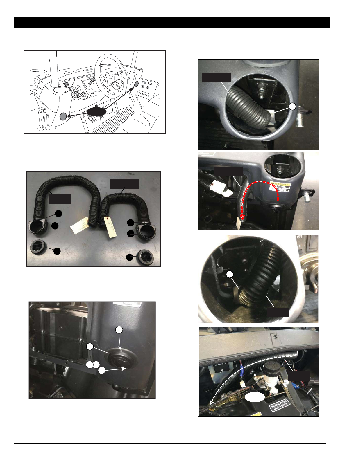
6. Cut the 2” flexible hose (#19) into six pieces as
listed. (Lightly stretch the entire piece untll it is
12ft long then mark out each length)
a. 300mm (12 in.) to driver foot louver
b. 300mm (12 in.) to passenger foot louver
c. 550mm (22 in.) to passenger defrost louver
d. 550mm (22 in.) to driver defrost louver
e. 710mm (28 in.) to passenger dash louver
f. 1200mm (47 in.) to driver dash louver
7. Identify one end of each hose to assist with
routing and connecting to the heater assembly
later.
NOTE: When cutting the dash, take care not to
damage electrical harness, structural frame or
components located behind the dash.
8. Identify the wiring harness connected to the
brake oil level sensor. Secure it with a cable tie to
reduce likelihood of damage when cutting the
dash.
NOTE: The wire harness should be disconnected
and rerouted under the frame member below it to
ensure there is no interference with the defrost
vent.
Wire Harness
Secure harness down to
reduce likelihood of cutting
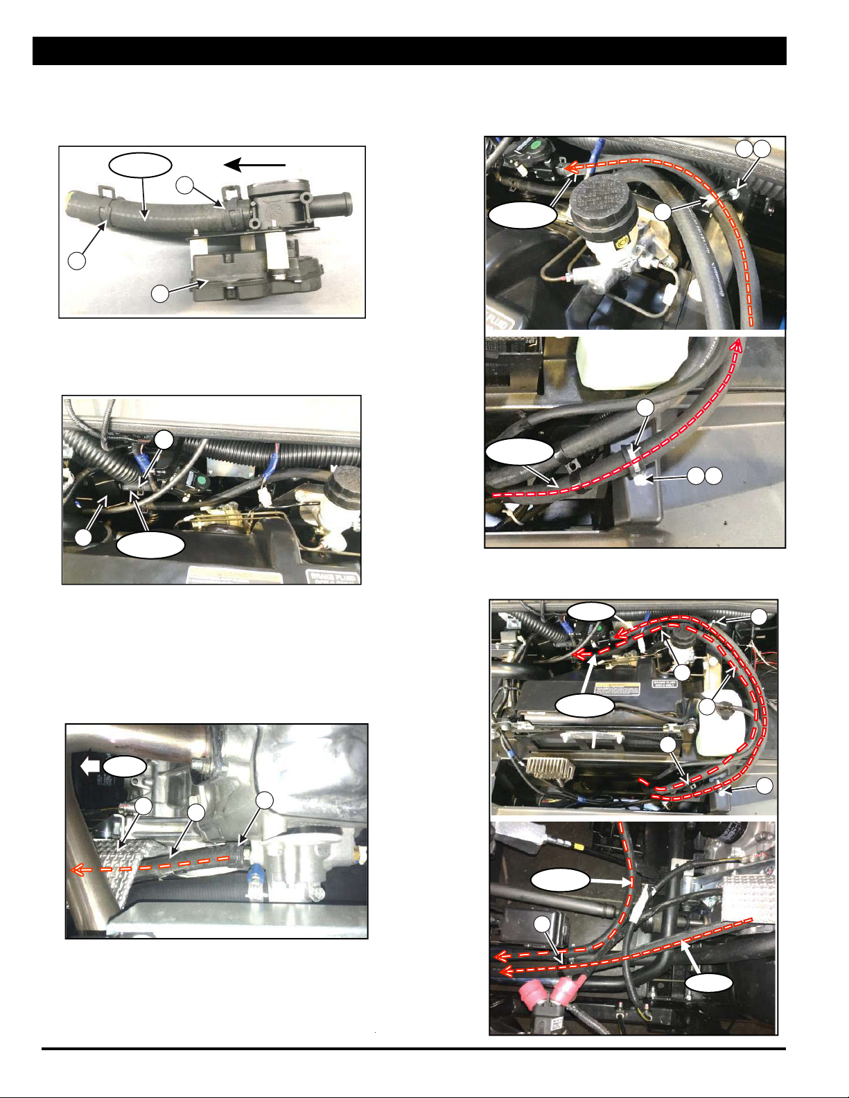
9. Use the cutting template provided at the end of the
manual to mark and cut the two openings shown
for the defrost louver. Drill two 6mm holes at the
marked locations (driver side shown, mirror for
passenger side).
Template
6mm
Hole
6mm
Hole
Align
Edge
Align
Edge
10. Prepare the installation of both defrost louver
plenums (#12) by connecting the two 550mm
(22 in.) long flexible hose cut in step 6. Secure
one hose to each plenum (#12) using a plastic
tie (#5).
5
5
13
13
12
Hose
29
12
11. Install the defrost louver plenum (#12) and
defrost louver (#13) to the holes cut. Secure
with screw defrost (#29) (Driver side shown,
mirror for passenger side).
12
29
29
13
12. Route the 2” flexible hose from the defrost louver
plenum (#12) to the glove box opening as shown.
Wire Harness
Routing
Passenger
Defrost
Hose
Routing

5 PRINTED IN THE USA © KUBOTA TRACTOR CORPORATION 2023
ASSEMBLY PROCEDURE
Heater Kit
13. Cut two openings for the round louver (#7) by using a
70mm (2 ¾ in.) hole saw in the locations shown.
Holes
14. Prepare the installation of both louver adapters (#8) by
connecting the 2” flexible hose cut in step 6. Secure
one hose to each louver adapter using a plastic tie (#5).
Driver’s Side
47in Hose
Passenger’s Side
28in Hose
8
5
7
5
8
7
15. Align the trim bezel (#9), as shown, and drill two 2mm
(0.089 in.) pilot holes. Secure with screws (#17). Install
the louver adapter (#8) and round louver (#7) as shown.
9
87
17
17
16. Route the 2” flexible hose from the louver adapters
(#8) to the glove box opening as shown. Avoid
contact with steering shaft and sharp edges.
Passenger’s Side
28in Hose
8
Passenger’s Side
28in Hose
8
Driver’s Side
47in Hose
Steering
Shaft
Driver’s Side
47in Hose

6 PRINTED IN THE USA © KUBOTA TRACTOR CORPORATION 2023 Heater Kit
ASSEMBLY PROCEDURE
17. Drill two 1/8” (3mm) holes in the lower dash, as
shown, to install the floor outlet casing (#11) for the
floor outlet. Use the floor outlet casing (#11) as a
guide for drilling.
Holes
18. Assemble the round floor louvers (#1) to the bracket
(#11) with the foam gaskets.
11
1
Foam Gasket
1
Tab
Rotate 45°
Slot
19. Prepare the installation of the floor outlet casing (#11)
and round floor louvers (#1) by connecting the 300mm
(12 in.) 2” flexible hose cut in step 2. Secure one hose
to each round floor louver using a plastic tie (#5) as
shown.
Correct Install
Incorrect Install
2” flexible hose (12”)
11
20. Install the floor outlet casing (#11) to the back
side dash panel using the two holes drilled
and the 1/8” rivets (#30). Route the 2” flexible
hose from the floor outlet louver (#1) to the
glove box opening as shown.
11
30
30
1
1
21. Position the heater unit in the glove box opening
with the hose connections towards the center of
the machine, and the electrical harness towards
the front.
CAUTION: Make sure not to crush or damage
the heater hoses.
22. Connect the six pieces of 2” flexible hose from the
louvers to the heater unit connectors as listed.
Secure each hose with a plastic tie (#5).
NOTE: See step 6 for quick reference of the six
hose pieces.
Foam Gasket
77
13 13
11
To front of machine

ASSEMBLY PROCEDURE
7 PRINTED IN THE USA © KUBOTA TRACTOR CORPORATION 2023 Heater Kit
23. Loosen the clamp on the drain tube from the dash.
Route as shown.
Clamp
Drain Tube
6
24. Install the bracket (#10) to the frame using the M6
screw (#27), M6 flat washer (#25) and M6 nyloc
nut (#26). Place the heater assembly (#6) in the
opening so the filter can be accessed for cleaning.
Secure the heater assembly (#6) inside the glove
box opening using the screws (#15) and washers
(#16) as shown.
10
27 2526
15 16
15 16
Filter
25. Using a clean storage container, drain and capture
the engine coolant from the drain shown. Ensure
the radiator cap is removed to completely drain.
Replace both drain plugs once completed and
tighten.
Front Skid Plate
Drain
Plug
26. Remove the underseat tray, support cover and
driver’s seat.
Underseat
Tray
Support
Cover
27. Remove the exhaust “HOT” shield.
Bolt
Exhaust
“HOT”
Shield
Bolt
Bolt
Bolt
Exhaust
“HOT”
Shield
CAUTION: Make sure not to crush or damage
the heater hoses.
NOTE: Refer to the machines operator manual for
detailed instructions on draining and bleeding the
coolant system

8 PRINTED IN THE USA © KUBOTA TRACTOR CORPORATION 2023 Heater Kit
ASSEMBLY PROCEDURE
28. Prepare the 5/8” hose bead x 3/8” NPT fitting (#20)
and 5/8” hose bead x 3/8” NPT 90° fitting (#21)
with PTFE thread seal tape.
29. For current models: Locate the engine coolant inlet
plug on the passenger side of the machine. Remove
the plug with a 8mm hex allen wrench. Install the 5/8”
hose bead x 3/8” NPT 90° fitting (#21) and position as
shown.
21
30. Locate the engine coolant outlet plug behind the
driver’s seat. Remove the plug with a 8mm hex
driver and socket extension.
31. Install the 5/8” hose bead x 3/8” NPT fitting (#20).
Plug
Plug
20
For early 2022 models and older: The engine
coolant inlet plug is in the same spot. However, there
is a yellow oil engine gauge located adjacent to it.
See below.
Remove the plug with a 8mm hex allen wrench.
Install the 5/8” hose bead x 3/8” NPT 90o fitting
(#21) and position as shown.
Plug
Oil Engine
Gauge
Plug
21
Oil Engine
Gauge

9 PRINTED IN THE USA © KUBOTA TRACTOR CORPORATION 2023 Heater Kit
ASSEMBLY PROCEDURE
32. Prepare the 5/8” heater hose (#3) for installation
by cutting the following length pieces:
(A) Inlet hose: 3850mm (152 in.)
(B) Outlet hose: 3300mm (118 in.)
(C) Heater valve connection: 150mm (6 in.)
33. Connect hose (A) - Inlet hose 3850mm (152 in.) -
to the 5/8” hose bead x 3/8” NTP 90° fitting (#21)
installed to the engine. Secure with 5/8” hose
clamp (#4).
34. Route hose (A) - Inlet hose 3850mm (152 in.) 5/8”
heater hose:
• Route it over the engine intake tube, along the
radiator hose, avoiding the 4WD shaft.
Intake Hose
4
4WD Shaft
Hose (A)
Hose (A)
• Follow the radiator hose to the radiator.
Pass under and in front of the radiator.
Intake Hose
4
Hose (A)
• Route around the radiator catch bottle, behind
the brake oil reservoir, and under the dash to the
heater assembly (#6).
Hose (A)
Radiator
catch
bottle
Brake oil
reservoir
6
• Remove the blue cap from the heater assembly
(#6).
• Connect hose (A) - Oulet hose 3850mm (152 in.)
5/8” heater hose - to the lower hose connection of
the heater assembly (#6).
Hose (A)
• Secure the hose with 5/8” hose clamp (#4).
4
Hose (A)

ASSEMBLY PROCEDURE
10 PRINTED IN THE USA © KUBOTA TRACTOR CORPORATION 2023 Heater Kit
35. Connect valve (C) - Heater valve connection
150mm (6 in.) 5/8” heater hose - to the heater valve
assembly (#2) using the 5/8” hose clamps (#4).
Ensure the correct direction of the valve as shown.
Valve (C)
4
Flow Direction
4
2
• Connect valve (C) - Heater valve connection
150mm (6 in.) 5/8” heater hose - to the heater
assembly (#6). Secure with 5/8” hose clamps
(#4).
2
4
Valve (C)
38. Secure hose (B) - Outlet hose: 3300mm (118”) -
with two 5/8” P-Clamps (#14) with nut (#26) and
screw (#27).
Hose (B) 14
26
27
Hose (B)
14
25 26
39. Secure hose (A) and hose (B) together with dual
clamp tie wrap (#22) as shown.
Hose (A)
Hose (B)
22
22
22
14
Hose (A)
22
Hose (B) 14
36. Connect the inlet hose 3300mm (118”) to the 5/8”
hose bead x 3/8” NTP fitting (#20) installed to the
engine. Secure with 5/8” hose clamp (#4).
37. Route hose (B) - Outlet hose: 3300mm (118”) :
• Along the radiator hose under the exhaust heat
shield.
• Follow hose (A) - outlet hose 3850mm
(152”) 5/8” heater hose 5/8” - to the heater
valve assembly (#2)
• Connect to heater valve assembly (#2) and
secure with 5/8” Hose clamp (#4).
44
4
Front

ASSEMBLY PROCEDURE
11 PRINTED IN THE USA © KUBOTA TRACTOR CORPORATION 2023
Heater Kit
40. Reinstall the exhaust “HOT” shield.
• Disconnect the negative terminal from the battery
before working on the electrical circuit.
• Do not short circuit the battery, starter motor or
electrical circuits.
41. Prepare to install the main wiring harness (#23) by
identifying the connectors.
Fan Switch
Potentiometer
Fuse Holder (3A)
To
heater
assembly
To heater valve
Ground x2
Fuse
Holder
(20A)
To accessory
power supply
Relay
To 12V positive supply
42. Start by connecting the main wiring harness (#23)
to the fan switch and potentiometer on the back of
the glove box cover control panel (#18).
Potentiometer
connector
Fan Switch
14
43. Pass the main wire harness (#23) through the glove
box opening over the heater assembly towards the
front of the RTV. Connect to the heater assembly.
23
6
Heater Assembly
Connector
Front
44. Route the main wire harness (#23) across the
machine towards the driver’s side of the radiator.
Connect the two ground ring terminals ensuring the
staking order is, bolt, heater ground, factory ground
then frame in location shown.
Connect the main wire harness (#23) to the valve
assembly (#2).
Ground Ring
Terminal
Valve assembly
connector
Hood support
pivot
Front
45. Secure the relay to the frame using M6 screw (#27)
and nut (#26) as shown.
Locate the accessory power supply on the factory
harness (blue tape) adjacent to the factory head
lamp switch connector. Install the jumper wire
harness (#24) and connect the main wire harness
(#23) to one of the two jumper wire terminals.
26
27
Relay
Factory Accessory
Connector
24
23
Optional Winch/Secondary Accessory Wire
CAUTION: To avoid pinching wires and the risk of
an electrical short, do not pinch the wire harness with
the zip ties.
23

ASSEMBLY PROCEDURE
12 PRINTED IN THE USA © KUBOTA TRACTOR CORPORATION 2023 Heater Kit
NOTE:
(1) The jumper wire harness (#24) should
only be used to activate two relays. Do not connect
multiple accessories direct to the factory accessory
power as this can overload the circuit;
(2) Maximum accessory circuit load 10A.
46. Route the main wire harness (#23) under the
machine following hose (A) and (B) under the
radiator towards the engine. Connect to the 12V
terminal located under the driver’s seat. Ensure
stacking order is nut, heater connector, factory
connector then terminal.
23
12V Terminal
47. Remove the radiator cap and fill with the coolant
previously drained (if captured in a clean container).
Replace the radiator cap.
48. Reconnect the negative terminal to the battery. Turn
the ignition key to accessory position. Check that
the fan works for all three speeds: low, medium and
high.
49. Bleed the cooling system to remove air. Open the
bleed screws indicated in the figures below. Close
them when no more air escapes from them.
Start the engine and the heater fan, turn the
temperature control dial to maximum. Run the
engine at idle until the radiator fan cycles two times.
50. Inspect the system for fluid leaks and correct as
required.
51. Check for heat coming from the defrost louvers,
dash louvers and floor louvers.
52. Stop the engine and allow the radiator to cool.
53. When the radiator is cool, remove the radiator cap
and check the coolant level in the radiator. Add
coolant to the radiator and recovery tank as
required.
NOTE: Do not mix coolant types. Use Kubota
coolant.
54. Reinstall under seat tray, cover support and driver’s
seat.
55. Reinstall the hood.
56. Reinstall the windshield (if removed).
Legal Disclaimer
Kubota Tractor Corporation notes that specifications and technical
information are subject to change without notice and Kubota does
not represent or warrant that the information in this publication is
completely accurate or current; however, Kubota used reasonable
efforts to set forth and include accurate and up to date information
in this publication. Kubota disclaims all representations and
warranties, whether express or implied, including, but not limited
to, warranties of merchantability and fitness for a particular
purpose and Kubota shall not be liable for any damages, whether
compensatory, direct, indirect, incidental, special, or
consequential, arising out of or in connection with the use of this
publication, or the information therein. The Product(s) described in
this Publication are designed and manufactured only for the
country in which they are initially wholesaled by Kubota. Kubota
does not provide parts, warranty or service for any Product which
is re-sold or retailed in any country other than the country for which
the Product(s) were designed or manufactured.
KTC10_23_RTV_1

Cutting Template: Defrost Louver
Driver Side:
Passenger Side
Table of contents
Popular Heater manuals by other brands

MILL
MILL NE900WIFI Assembly and instruction manual

Home
Home FK 31 instruction manual

Lasko
Lasko 754200 operating manual

DèLonghi
DèLonghi KH770925V instructions

Haverland
Haverland ePOINT Instruction & installation manual

Phillips & Temro industries
Phillips & Temro industries G1600 installation instructions