KUDOS ORIGINAL Series User manual

KUDOS
REFRESHING INNOVATION IN SHOWERS
1500/1700 BOWSLIDER
Installation Instructions
Please read these instructions before installing, as incorrect fitting will invalidate the guarantee.
Carry out each stage before moving onto the next. Do not dispose of packaging, no claims for
damaged or missing parts will be accepted if the packaging has been disposed of.
If you are unsure about these instructions please contact Kudos Shower Products:
Customer Service Helpline: 01539 564040
ORIGINAL RANGE
TOOLS REQUIRED KEY STAGES
IMPORTANT
GENERAL - for the frame work and fixings use only warm soapy water and damp cloth/ sponge on a regular basis. After cleaning
please rinse with clean water to remove any residue.
Do not use abrasive scouring powders, chemicals or aerosol cleaners - these may result in damage to the surfaces, in particular, the
plated component parts. See instruction below for glass cleaning advice.
CLEANING
LIFESHIELD
SILICONE
SEALANT
Check appearance of shower enclosure - any defects must be
reported to Kudos Shower Products before assembly/installation
Claims for imperfections will only be accepted prior to
assembly/installation
Ensure the top of shower tray is level in all directions
Any claims made under the terms of the Lifetime Guarantee
must be reported to Kudos within 21 days of the fault occurring
Check the enclosure adjustment sizes are suitable for your
installation
Prior to tiling, any gap or crevice between the rim of the tray and
the wall must be filled with silicone sealant flush with the rim of the
tray - see Fig.1
Waterproof the walls using ceramic tiles/shower panels etc. before
installation of the shower enclosure
Fully seal between tiles/shower panels and the tray BEFORE
installing the enclosure - see Fig.2
Use care when drilling into the walls to avoid hidden pipes or
electric cables
FIG.1 FIG.2
Once the tray is installed but
before the tiles are fitted any
crevice between the tray and
the walls must be filled with
silicone sealant flush with the
top of the tray.
Once the walls have been
tiled but before the
enclosure is installed, the
tiles must be silicone sealed
to the tray all of the way
around in one continuous
bead.
Your Kudos Product is pre-treated with Life Shield on the inside surfaces only. While this makes cleaning the glass a lot easier and
helps prevent the build up of harmful lime-scale and soap deposits the glass still needs to be maintained on a regular basis. We
recommend the use of a detergent and aroma free glass cleaner (A 50/50 mix of Vinegar and Water works well!!) Strong detergents
and abrasives can damage the coating.
DO NOT use abrasive cleaners or abrasive scrubbing equipment for cleaning!!
DO use a squeegee to remove remaining droplets of water from glass after showering, any build up of residue can be removed easily
using an appropriate cleaner and agitation from soft cleaning equipment
THESE INSTRUCTIONS TO BE LEFT WITH THE CUSTOMER
?Decide handing of the door & change
door glass handing if necessary
?Assemble the frame work
?Remove the clip -in extrusions
?Position and level the frame work in situ
Drill walls and fix connector posts level
Secure frame work to connector posts &
adjust so that level
?Fit the fixed panel
?Fit the sliding door
?Silicone seal the enclosure
?
?
?Flat-Headed Screwdriver
?Pozi-Drive Screwdriver
?Spirit Level
?Tape Measure
?Silicone Sealant
?4mm & 2.5mm Allen Key (Supplied)
?Electric Drill
?7mm Drill Bit (Masonry)

23
4
7
5
6
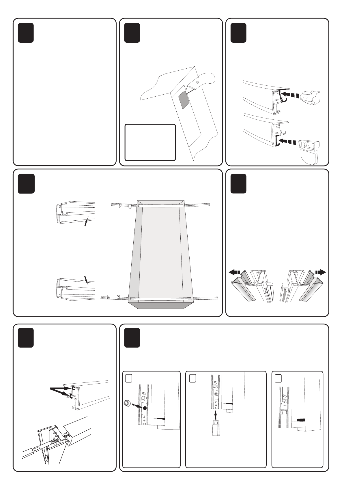
Insert spiral cam as
shown in the image
Slide the main height
adjuster block into the base
of the wall post, it will “Click”
when engaged
When fitted the
height adjuster
block should be
flush with the base
of the wall post
123
Insert the height adjustment blocks into the base of the wall posts as
shown. You will need to lift the wall post slightly to allow space to fit
the height adjustment block.
SCREW
PORTS
OPEN SIDE
FIXED PANEL
SIDE
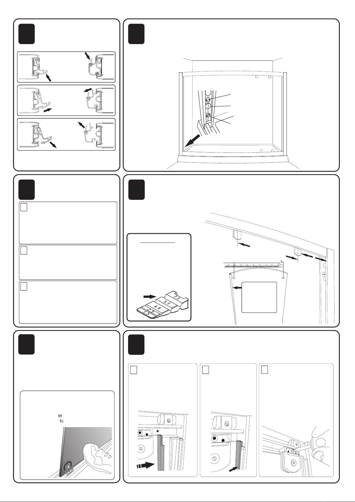
Remove the fixed panel
patches from the fixed glass
(glass without handle) by
removing the allen key screws. Keep
the inner patch covers safe. Slide x1
Stop Block into each rail as shown,
and then x2 Fixed Panel Patches into
each rail as shown. You do not need to
secure these fixings into the rail at this
stage.
Identify both wall posts. The
wall post with the plastic
flipper seal as shown will be
the opening side of the enclosure,
the one without the seal will be the
fixed panel side. Please ensure that
the wall post without the flipper
seal is to go to the end of the rails
with the pre drilled hole as shown in
stage 4.
AT THIS STAGE REMOVE THE
CONNECTOR POSTS FROM BACK OF
WALL POSTS
VIEWED FROM ABOVE
Secure the wall posts to the
rails using the X8 No.6x30PH
screws from the screw
Assembly Pack. Please ensure that
each screw locates into the relevant
screw port in the rail as shown. We
recommend that you start with the top
rail.
To help with assembly insert the rails through the box as shown. The
rails are handed, the fixed panel end can be identified by the pre drilled
hole at the end. These instructions show a Left Hand Entry
Cut out each end of the box
lids where shown. These
will help with the assembly
of the enclosure. If you have help
then these may not be necessary.
Ensure that the
screws are fully
tightened
This stage is best carried out
against a wall. Start off with the
top rail and ensure that the
outer face of the rail is facing
towards the wall. Please
note the Pre-Drilled hole at the
end of each rail.
X1
X2
Fixed panel patch
from fixed glass
Stop block from
installation pack
1
Looking at the door glass from what
would be the outside, with the
wheeled units at the top, check
which side of the door the handle is
on, this will tell you what handing the
door is, if you need to change the
handing of the door, change the
wheeled patches at the top of the
door with the quick release patches
at the bottom, along with the splash
seal. WHEELS ALWAYS TO TOP
We recommend that you then lay
something down to protect the tray
surface and position the door glass
with in the showering area at this
stage, as it can prove difficult to
move through the opening of the
enclosure at the later stages.
Check handing of door glass
then position glass in
showering area.
WE ADVISE
THAT THIS
INSTALLATION
IS CARRIED OUT
BY 2 PEOPLE
TOP
BOTTOM
CUT
HERE

Apply pressure
to the indicated
face of the
extrusion
Release the
inner/outer edge
of the extrusion
over its entire
length
Lift the extrusion
out and away from
the wall posts
89
10 11
12 13
Carefully tear off the box and
discard. Then remove the
extrusions as shown below.
Replace Connector posts that where removed in stage 5. Offer
enclosure onto the tray and expand frame equally into the opening using
the x3 lateral adjustments on each wall post so that the frame wedges
into place. Level the bottom rail if required using the height adjustment.
Mark the base of the connector posts to the wall.
IF USING A SIDE PANEL PLEASE REFER
TO SIDE PANEL INSTRUCTIONS AFTER
THIS STAGE
CAREFULLY
REMOVE THE FRAME
FROM THE TRAY
1
1
2
2
3
3
Remove connector posts and
position to marks made in
previous instruction, ensure they
are level, mark screw holes then
drill holes. CHECK FOR PIPES
AND CABLES
Insert wall plugs or fixings
suitable for your walls. Then
secure connector posts to wall
using X6 No.8x30 PH screws
supplied
Offer frame work to connector
posts, and secure using X6
No.8X30 PH screws, level door
frame using adjustments shown
in stage 9, ensure the wall posts
are straight and not bowed.
Carefully lift fixed glass
panel into the enclosure and
secure to fixed panel patches.
Make sure you have the 4mm Allen
key & inner patch covers to hand.
Ensure the rigid seal is to the wall
post with the Life Shield treated
surface to the inside.
Place fixed glass onto the bottom patches
and hold firm with your foot. Push the top
of glass onto locating holes in top patches
and re-fit the inner patch covers. Repeat
for the bottom patches.
Measure the centres of the holes in the fixed panel in a straight line
a across the inside of the curve, once done position the patch closest to
t the wall post 200mm away from the post, then space the second patch
the equal distance from this to the fixed panel holes (measure to the centre of
the fixed panel patches). Repeat for the patches at the bottom.
Slide the fixed panel
up to the wall post,
slightly loosening the
allen key screws
may make this easier
Ensure the lip on
the rigid seal
locates into the
extrusion over it’s
full length
Using X4 6x20PH
screws secure the
patches into the pre
drilled holes, if the holes
do not line up loosen
the allen key screw and
move patch on glass to
align, re-tighten all allen
key screws.
Re-fit the extrusions by reversing the procedure in stage “8" Slide
fixed panel back to the fixed side wall post, ensure lip of seal fully
locates into the groove in the extrusion. Once secured ensure all
allen screws are fully tightened.
Seal
IMPORTANT
Before fitting the fixed panel
glass, ensure that the Shim
Strip is placed between the
bottom rail and the tray half
way along it’s length, this will
support the weight of the
glass and prevent the bottom
rail bowing
SHIM
STRIP
Screw fixing position
(x3 per wall post)
Lateral Adjustment
(Anti-Clockwise to
expand)
Height adjustment
(Level bottom rail)
200mm
Equal distance to
fixed panel hole
centres
This rigid seal
on the edge of the
fixed panel glass
is to go to the
wall post with the
lip to the inside

3
14 15 16
17 18 19
20 21
Insert glazing seals as
shown, around the
outside of the fixed panel.
Also at this stage fit the inner fixed
patch covers as shown, you will not
be able to fit all of these once the
door glass is installed.
Remove the wheel patch
fixings from the door glass
using the 4mm allen key
supplied. Sit these patch fittings into
TOP rail upside down then turn the
right way around to lock them into the
rail.
Carefully lift the sliding door
glass, and position to the
wheeled patches. Support the
weight of the glass on your foot and
secure the inner cover back on using
the 4mm allen key supplied.
Ensure the shoulders of the patch
fittings are tight against the top
edge of the glass.
FIT COVER CAPS, to all
patch fittings and each wallpost
Secure wallpost cover caps
using No.4 x 10mm long screws
provided.
FIT VERTICAL DOOR seal
onto the opposite edge of the
sliding door to the handle.
Position stop blocks to prevent the
handle of sliding door impacting on
edge of fixed panel, then tighten allen
key grub screws with 2.5mm Allen
Key.
TIP
If seals feel tight, then
wetting in clean water
will help. Ensure you do
not stretch the seals. Trim
to correct length.
Adjust the hanging of the door
so that the closing edge of the
glass meets the closing seal
evenly over it’s entire height. Gain
access to screw “A” by removing the
top patch cover.
SLIDING DOOR
VIEW
FROM INSIDE
TOP
TO RAISE THIS
SIDE OF DOOR
USE SCREW
‘A’
TO LOWER
THIS SIDE OF
DOOR USE
SCREW ‘B’
A
B
TO RAISE THIS
SIDE OF DOOR
USE SCREW
‘A’
TO LOWER
THIS SIDE OF
DOOR USE
SCREW ‘B’
A
B
A
B
Roller bearing adjustment- using
screwdriver, loosen screw (do not remove), re-
position in slot and re-tighten.
Patch fitting adjustment- using allen key,
loosen screw (do not remove), lower glass and
re-tighten.
FIXED
DOOR
Silicone seal the wallposts.
Both wallposts should be
sealed vertically to the tiled /
panelled walls on the Outside &
Inside of the enclosure.
Silicone seal the enclosure
to the tray on the outside only
You should also seal the joint
as shown.
IMPORTANT!! Do not seal to the tray
on the inside, this will prevent drainage
of the frame work and will cause
leakage problems
Seal joint at both ends
of the bottom rail
Keep inner fixings
to hand when
positioning the
glass door
?
?
Check the running of the
door, vasaline can be applied to
the bottom track to improve the
sliding action
Check that the shim strip has
been installed under the bottom
rail
?Check that all the screws and
fittings are fully tightened
?Ensure that the quick release
levers are to the bottom of the
door
?Leave for 24hrs before use to
allow silicone sealant to cure
Bottom & Top
TIP
Support weight of
glass on your foot
when securing to the top
wheel patches
PLEASE ENSURE THAT AFTER ADJUSTMENT
ALL SCREWS ARE FULLY TIGHTENED
Seal
shown
shorter
for clarity
12
This manual suits for next models
2
Other KUDOS Bathroom Fixture manuals
Popular Bathroom Fixture manuals by other brands

Philips
Philips AWP1705 user manual

Franke
Franke AQUALINE-THERM SWV AQLT0036 Installation and operating instructions

Grohe
Grohe Rainshower 28 368 manual

Franke
Franke PR3O0020 Installation and operating instructions

Signature Hardware
Signature Hardware Berwyn SHRS820R2GCP quick start guide

VADO
VADO VEL-149RRK-RO-CP installation guide

Livewell
Livewell Grabcessories 61023 manual

Gessi
Gessi OUTDOOR 63204 manual

Wellis
Wellis Rundo ACS0196 Instruction guide

Geberit
Geberit IDO PORSGRUND Showerama 10-40 Operating and maintenance instruction

Hamwells
Hamwells HomeSpa quick start guide

Hans Grohe
Hans Grohe Raindance Select 26466000 Instructions for use/assembly instructions