4Issue 01 MAR.19
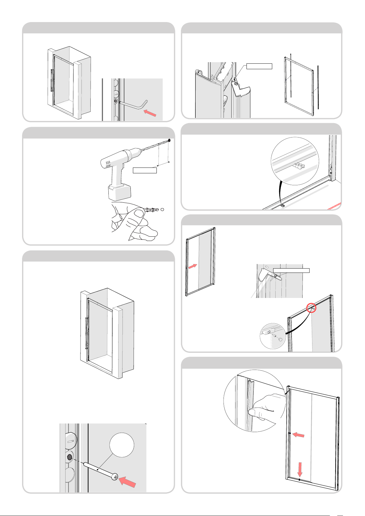
Step 14 - Fixed Glass Panel
Step 15 - Fit Seal to Fixed Glass Panel
Step 10 - Drill Mounting Holes & Insert Wall Plugs
1. Remove the frame from the
recess, loosening the adjustment
screws along each side if required
(do not adjust the bottom height
adjustment screws). Placing safely
off to one-side.
2. Using a 7mm masonry drill bit
and drill (or appropriate drill bit if
drilling tiles), drill six holes using the
‘spot’ marks from step 8, each hole
should be 45mm in depth.
3. Insert the six ‘6mm Wall Plugs’
into the six holes.
Step 11 - Fitting the Frame
1. Insert the frame back into position, tighten the adjustment screws once
again until the frame is even in the gap and held fast. Using a spirit level, check
that the frame is ‘plumb’ vertical and the holes in the frame line up with the
plugs in the wall. Ensure that the frame is not twisted or buckled and square
on all sides.
2. Using 6 x No.8 Pan-head 60mm screws provided, screw the frame to
the wall on each side. Be sure not to over tighten the middle screws (nger
tighten only) as this may cause “bowing” of the door frame. Using the ‘clip-
in’ extrusions as a straight edge, rest the straight edge against edge side of
the frame, you’ll be able to see any bowing that may have occurred. The
middle screws may now be adjusted to assist in plumbing the door frame
and removing the “bow.”
Step 12 - Re-t Clip-In Extrusions
1. Re-t clip-in extrusions, which were removed in stage 4. The clip-in extrusion
with “ipper seal” should be on the handle side of door. Ensure the leading edge is
properly located along the full height before pressing the clip-in extrusion into the
door frame, it will not locate properly if twisted.
45mm Deep
1. Fit the xed panel glass, carefully t glass panel into slot in wall-
post, ensuring panel is square to wall. Tap the plastic prole rmly
into groove of clip-in extrusion along full length, if this is not done,
the xed panel glass may interfere with the door glass when this
is installed. Ensure that the glass surface treated with LIFESHIELD
faces to INSIDE of shower enclosure - see label on glass.
Inserting the glazing seal, starting at top and working
downwards, trim excess length. If tight, lubricate
glazing seal with water. Do not stretch seal when
inserting, because, after cutting to length, the seal
will shrink and leave a gap.
If the seal is misshapen, soak in warm water, not
boiling, for 2-3 minutes prior to use.
Step 13 - Shim Frame
1. Often shower trays have different
angled top faces, in order to help keep the
frame supported use the ‘Shim (M97-01)’
supplied. On the inside of the enclosure
measure the gap between the bottom of
the rail and top of the tray, select the height
required from the shim strip supplied,
break off and insert under rail at xed panel
bracket position . This will support rail when
glass is tted. The shim will be concealed by
silicone sealant later.
2. Attach the ‘Glass Patch Clamps’
(DCM-85-ASM) top and bottom of
the xed panel. Tighten the ‘No.6x12
PH S/S Screws’ into the two clamps,
ensuring the screws engage centrally
with the two pre-drilled pilot holes
in the rails. Finally, ‘push t’ the Patch
Guide Caps (M276-01) into the two
clamps.
Locate Plastic Profile in
1. Uncoil the two
‘Glazing Wedge Seals
(PlexF05),’ Insert the
seals to the outside
of the enclosure,
between the xed
glass panel and lip of
the metal frame, along
the side and across the
bottom.
Step 9 - Mark Position of Holes
1. Using a spirit level, check that the
frame ‘plumb’ vertical.
2. Using a 3mm rod (we recommend
a small Allen key or drill bit), place a
small amount of marking paste (we
recommend shoe polish) on the end
of the rod, and ‘spot’ through the 3
screw holes down each side of the
frame (blue lined).