CLEANING
For frame work and fixings use only warm soapy water and damp
cloth/sponge on a regular basis. Do not use abrasive scouring powders,
chemicals or aerosol products - these may result in damage to the surfaces.
See instruction below for glass cleaning advice.
IMPORTANT
Check that you have the correct packs and shower tray to
suit your installation
Check appearance of shower enclosure and tray. Any
defects must be reported to Kudos Shower Products
before assembly/installation. Claims for imperfections will
only be accepted prior to installation.
Ensure shower tray is installed level in all directions.
Prior to installation, any gap or crevice between tray and
walls must be filled with silicone sealant flush with the top
of the tray.
Waterproof walls (using tiles/shower panels etc.), before
installing the shower enclosure.
Care should be taken when drilling into walls to avoid
hidden pipes and electrical cables.
The blended water to the handset can be supplied from
above or below the enclosure:
OVERHEAD WATER SUPPLY:
Maximum ceiling height allowable (from top of tray) =
2835mm / 9’ 4”
NB- Please ensure that the ceiling entry point for this
supply is clear of any structural framework.
UNDER-TRAY WATER SUPPLY:
Overall height of enclosure (including shower tray) =
2036mm / 6’ 8”
We recommend that you fit lagging to the 2m flexible
hose if it is being installed into a situation where the
ambient temperature may drop below 5c.
Choose your Quartz Processor site and install.
Run data cable to recommended position for shower
control.
Connect 2 metre flexible hose to Quartz Processor.
NB- This connection must be carried out at this stage if
it is not possible to make the connection after the
shower tray has been installed, i.e, when installing the
tray directly onto a solid floor.
Install shower tray.
Apply finish to walls e.g. tiling.
Install shower enclosure.
Connect to flexible hose and fit Water Delivery Column.
THESE INSTRUCTIONS ARE TO BE LEFT WITH THE CONSUMER
1st
2nd
3rd
4th
5th
6th
7th
KEY STAGES TO INSTALLATION
INSTALLATION INSTRUCTIONS
FLAT PANEL
WALK-IN ENCLOSURES
WITH
1500 & 1700
SHOWER TRAYS
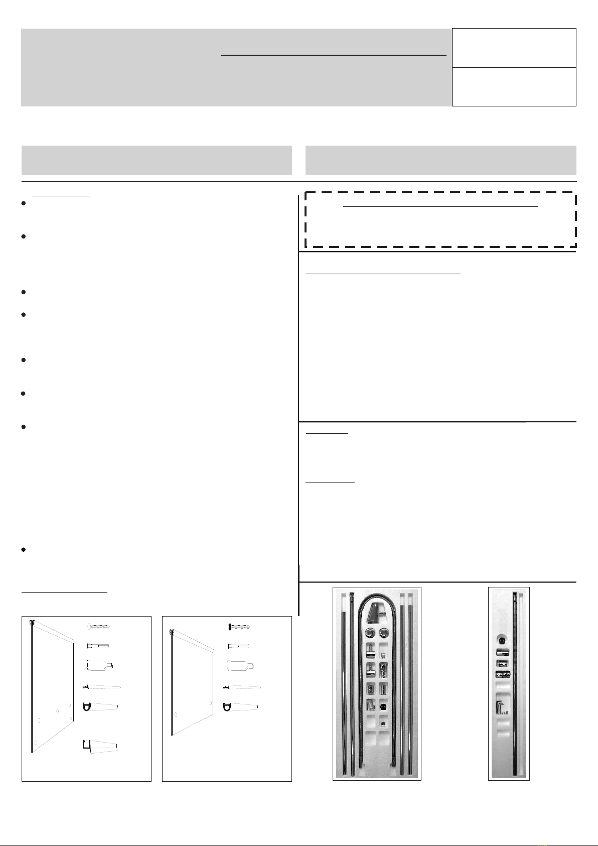
PACK CONTENTS
Please ensure that you have all the necessary components
before starting your installation.
PACK 5WA (for 1500 tray)
PACK 5WC (for 1700 tray)
FRONT GLASS PANEL
PACK 5WG
for 1500 &
SIDE GLASS PANEL
( 1700 tray)
Got a query? Then please contact the relevant number:
Please read these instructions throughout before installing as incorrect fitting will invalidate the guarantee
These installation instructions must be used in conjunction with the QUARTZ Installation Guide
For information on the Walk-In Enclosure/Shower Tray
Kudos Shower Products 01539 564040
For information on the Quartz Shower System
Aqualisa Products Limited 01959 560010
PACK 5WK
1000 / 1200
FRONT PANEL COMPONENT KIT
PACK 5WP
800 / 900 / 1000
SIDE PANEL COMPONENT KIT
FIXING SCREWS x 3
RAWL PLUGS x 3
SPACER BLOCK
GLAZING SEAL
BOTTOM SEAL
for WET ROOM
INSTALLATION
BOTTOM SEAL
for SHOWER TRAY
INSTALLATION
FRONT PANEL
with WALLPOST
ATTACHED
SIDE PANEL
with WALLPOST
ATTACHED
FIXING SCREWS x 3
RAWL PLUGS x 3
SPACER BLOCK
GLAZING SEAL
BOTTOM SEAL
for WET ROOM
INSTALLATION
HEALTH & SAFETY WARNING
DUE TO THE WEIGHT OF THE GLASS PANEL(s)
A MINIMUM OF TWO PEOPLE IS REQUIRED
TO MOVE AND INSTALL THIS ENCLOSURE
WITH
SHOWER TOWER
SYSTEM
Your Kudos product is treated with Life Shield on the inside and
outside surface. Though this helps prevent the build up of lime-
scale and soap deposits, the glass still needs regular
maintenance. We recommend the use of a detergent and aroma
free glass cleaner (A 50/50 mix of vinegar and water works well)
Strong detergents and abrasives can damage the coating.
After showering use a squeegee to remove droplets of water from
the glass.
LIFE SHIELD
KUDOS
U L T I M A T E 1


