Kurt 3600H Series Instruction Manual

3600H-Series Vise
“Hydraulic”
Base Assembly
Operating Instructions Manual
Manual de instrucciones de operación
3600H - Forward
3610H - Reverse
3620H - Forward, Short
3630H - Reverse, Short
ENGLISH ESPAÑOL

2ENGLISH |
Table of Contents
Introduction .................................................................................................................3
Setup Instructions......................................................................................................4
Operating Instructions .........................................................................................5-7
3600H Parts List...........................................................................................................8
3600H Mechanical Drawing ...................................................................................9
3610H Parts List........................................................................................................ 10
3610H Mechanical Drawing ................................................................................ 11
3620H Parts List........................................................................................................ 12
3620H Mechanical Drawing ................................................................................ 13
3630H Parts List........................................................................................................ 14
3630H Mechanical Drawing ................................................................................ 15
36BHU Parts List....................................................................................................... 16
36BHU Mechanical Drawing................................................................................ 17
Hydraulic Intensier Set-Up ..........................................................................18-19
Maintenance Schedule....................................................................................20-23
Troubleshooting Tips ............................................................................................. 24
Vise Data
Use this to ll out information about your vise for quick reference.
Purchase Date: _______ -_______-_______
Purchase Order: _______________________
Purchased From: _______________________
Delivery Date: _______________________
Serial No.: _______________________
Note:
Make sure to register your warranty online at kurtworkholding.com
Table of Contents
CAUTION:
Is used when your action or lack of action may cause serious
injury.

3| ENLGISH
Introduction
Thank you for purchasing a Kurt vise. You have just purchased one of
the best machine vises in the industry. The Versatile Lock 3600-Series
AngLock vise has a time proven design. The outstanding accuracy
of this product is second to none. Backed by a lifetime warranty, this
product will last forever when used and maintained properly.
The original Kurt Anglock vises are designed for precision clamping.
The“Pull-type”action of the 3600 Versatile Lock design reduces jaw
stationary deection by at least 80%. This vise has a one-piece body
and stationary jaw design which reduce weight and increases strength
while providing .0005 clamping repeatability. It oers ultra-high
precision through many important features. Features include: Ground
sides that allow side mounting, upright and back to back mounting,
using the body through holes allows side by side mounting.
With twelve dierent models ranging from standard lengths to short
lengths, forward to reverse and hydraulic to air this series of vises are
truly versatile. The short reverse conguration has the added benet
of easier programming by reducing the“reach-over” distance in the “Y”
axis. This makes it safer and easier for the operator.
The patented Anglock design allows the movable jaw to advance in
such a way that each pound of force forward induces a ½ pound force
downward which minimizes the jaw lift and increases accuracy. This
combined with the needle bearings increases jaw clamping pressure.
Other features include: 80,000 psi ductile iron body, hardened vise bed
& jaw plates, semi-hard steel screw.
Introduction
Induces 1/2 pound of force in this direction.
Spherical segment
(hardened) produces
“all directional”
alignment.
Each pound of force in this direction.

4ENGLISH | Set-Up Instructions
Set-up Instructions
Now that you have your new Kurt 3600-Series vise, it’s time to set-
up and begin using it. You will see that your new vise comes with a
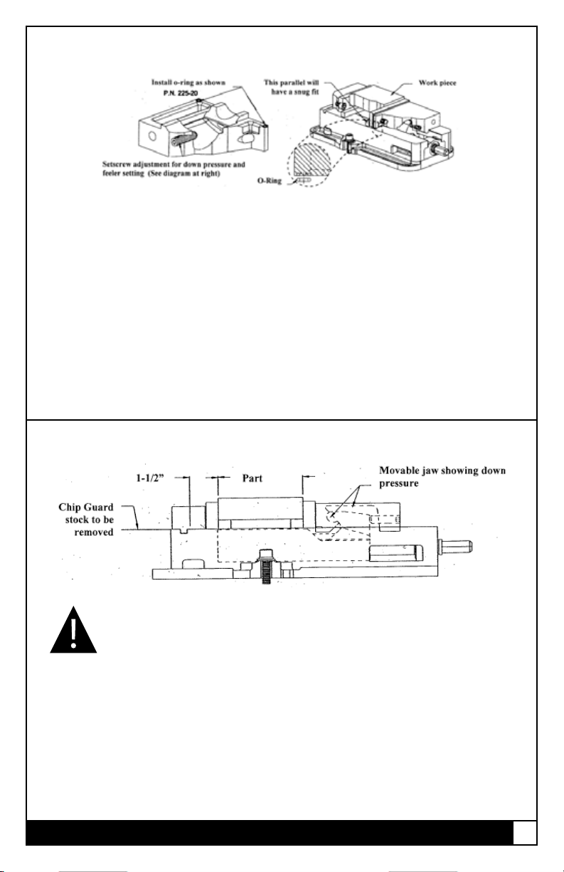
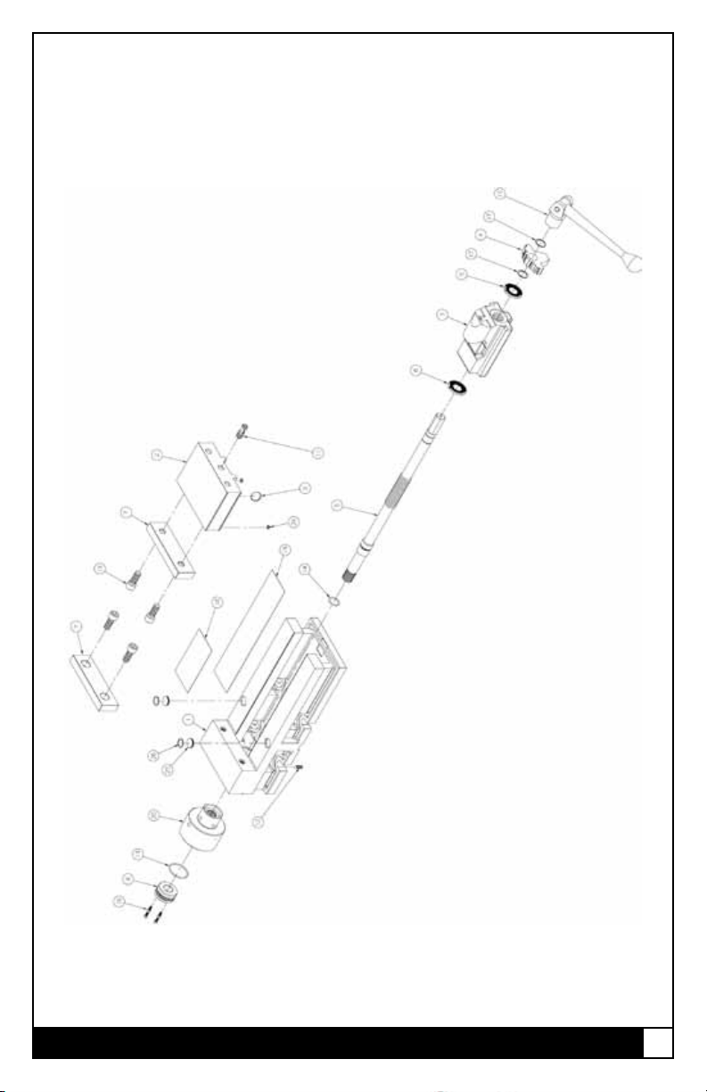
Kurt swivel handle, two chip guards (short & long) and an instruction
manual along with the O-ring installation guide supplied in the
shipping carton. The chip guard rests between the ways of the vise and
can be trimmed to size to help keep the chips out of the screw. The
handle is specically designed to provide maximum torque to your
vise. Your vise should be mounted to a clean at surface. The surface
and the vise must be free of any chips, dirt or debris of any kind. The
mounting surface can be honed if necessary. Clean the bottom of the
vise with solvent or other cleaner if needed. Air activated vises require
shop air power. Air lter/lubricator required.
To minimize vise bed deection, clamp your Kurt vise to your machine
table, pallet, or sub-plate using the built-in clamping slots provided.
To access the through holes, simply pick the edge of the protective
cap up and expose the C’ bored hole. Replace the cap after you have
mounted the vise to keep debris out of the holes. If you are mounting
the vise on it’s side or back to back, other clamping methods may be
required.
Additional clamping can be used, but may not be necessary. Please
be sure to exercise good judgment when securing your vise to the
mounting surface. Be sure your vise is secured and will not move when
applying the machine pressure.
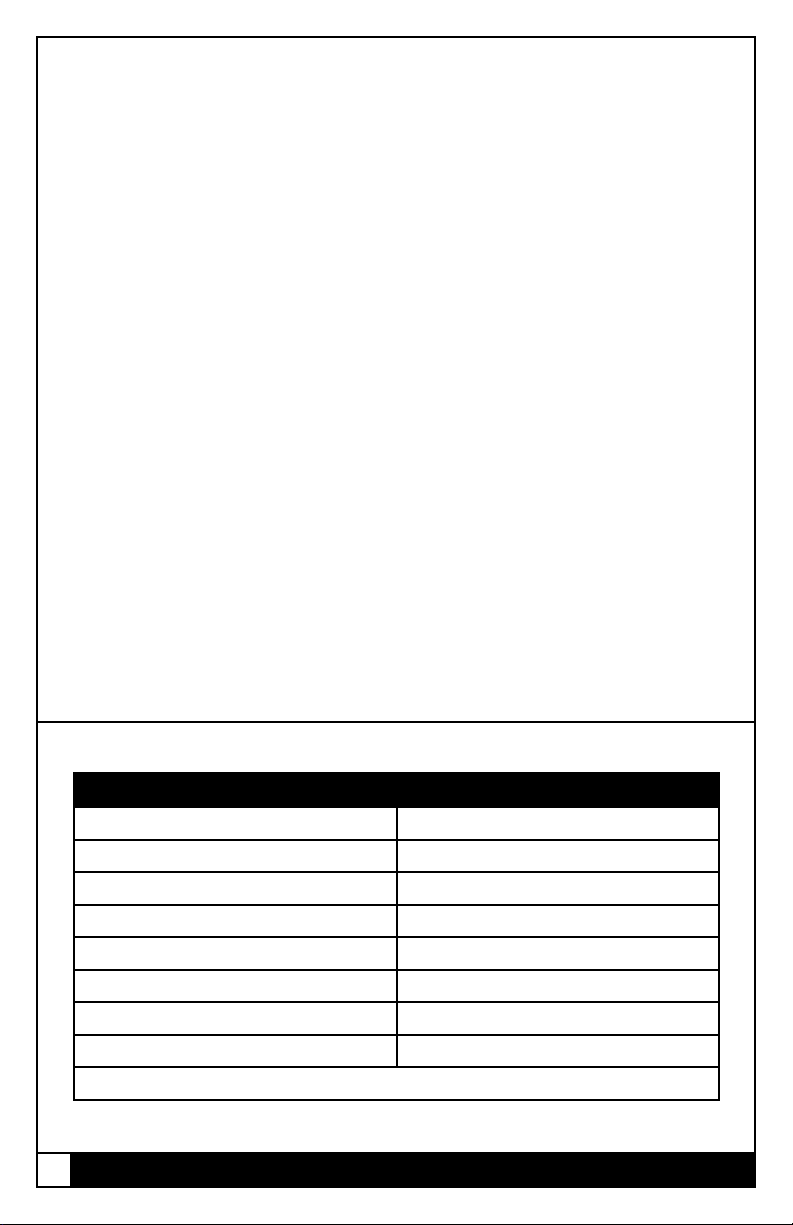
Manual Vise Clamping Force
Hydraulic PSI Hydraulic Series
400 1575
800 3150
1200 4725
1600 6300
2000 7875
2400 9450
2800 11025
3200 12600
Hydraulic displacement cu. In. 1.18

5| ENLGISH
Operating Instructions
For proper vise operation insert the handle on to the hex end of the
vise. Rotate clockwise to clamp and counterclockwise to unclamp
your vise. This handle combined with the correct amount of torque
will provide you with all the clamping force you will need to machine
your parts. Air pressure is only used for clamping purposes 1/4” stroke
maximum. All other operations remain the same. A high quality
calibrated torque wrench can be used if needed. DO NOT use any
other type of pressure to open or close your vise.
The uses of handle extensions, air impact wrenches, breaker
bars or hammer strikes are not recommended and will void the
warranty if used. This will also cause damage to the thrust bearing
and screw threads. If you need more clamping force you may need to
upgrade the vise to a larger one.
To properly clamp a part in your Kurt vise you should place the part in
the center of the jaws resting on the ways of the vise. Clamping only
on one side or above the movable and stationary jaws can result in jaw
lift or loss of accuracy. (See Fig. 1 on next page)
If one-sided clamping is necessary you MUST use a dummy part on
the other side. When using parallels or step jaws you must select a size
that keeps the bottom of the clamped part at or below the top of the
movable and stationary jaws. Always use jaw plates for clamping. If jaw
plates are not used damage to the mounting surface of the movable
and stationary jaw will occur. This will result in reduced clamping
accuracy and repeatability.

6ENGLISH |
Fig.1
Sketch #2A
Incorrect part
clamping.
Vise width
centerline
Sketch #2B
Correct part
clamping.
Sketch #2C
Correct part
clamping.
Sketch #2D
Correct part
clamping.
Non-
machined
spacer
Operating Instructions

7| ENLGISH
D40 Parts List
Proper O-Ring installation and usage
Proper Chip Guard installation and usage
Most jobs require a tight contact between the workpiece and the
parallels (see above). This option oered by Kurt Manufacturing
Company is ideal for that. The O-Ring installation will provide for the
movement needed when working with parallels.
Note: We do not recommend using this option with step jaws.
Installation: Install the O-Ring in the movable jaw as shown above in
two places. Tighten the adjustment set screw for a .002”space under
the front face of the movable jaw, then the jaw will tighten down
during clamping and provide down movement, pulling the part onto
the supporting parallel.
Example: Part plus 1 1/2 inches = Length of Chip Guard stock.
Note: Remove Chip Guard stock to lift vise. Corners of Chip Guard
stock if left extended as shown above could cause injury.
CAUTION:
Chip Guard stock shown above is provided to keep chips
from the nut and screw assembly and must be cut and
deburred to meet your application and safety needs.
*This Chip Guard stock should be cuto to ll the opening
between jaw plates.

8ENGLISH | 3600H Parts List
3600H Parts List
ITEM# PART # DESCRIPTION QTY.
1 3600V-1 Body 1
2 3600V-2 Movable Jaw 1
3 3600V-3 Nut 1
4 3600V-224B Screw Support 1
5 360HU-5 Screw (STD Hydraulic) 1
6 3600V-211 Internal Brush Seal 2
7 D60-7 Jaw Plate 2
8 3600V-8-P Retaining Nut, Two Piece 1
9 D60-9 Segment 1
10 D60I-10-SA Handle Assembly 1
11 3600V-11A Socket Set Screw, 1/2-13 1
12 Jan-78 Screw, SHSS, 1/4-20 x 3/4 1
13 3600V-128 O-Ring, Buna N, #129 1
14 3600V-99 O-Ring, Buna N, #117 1
15 00-1419 Screw, SHCS, 1/2-13 x 1-1/4 4
16 00-1191 Screw. SHCS, #8-32 x 3/8 4
17 3600V-147 Spiral Retaining Ring 2
18 3600V-248 Chip Guard, Short 1
19 3600V-249 Chip Guard, Long 1
20 36BHU Hydraulic Clamping Unit 1
25 225-20 O-Ring, Polyurethane #008 2
26 DLU4-96 O-Ring, #016 2
27 3600V-191 Protective Plug 2

9| ENLGISH
3600H Mechanical Drawing

10 ENGLISH | 3610H Parts List
3610H Parts List
ITEM# PART # DESCRIPTION QT Y.
1 3600V-1 Body, Machined, Versalock 1
2 3600V-2 Movable Jaw 1
3 3600V-3 Nut 1
5 361HU-5 Screw (Reverse Hydraulic) 1
6 3600V-211 Internal Brush Seal 2
7 D60-7 Jaw Plate, Purchased 2
8 3600V-8-P Retaining Nut, Two Piece 1
9 D60-9 Segment 1
10 D50-10A-SA Handle Assembly 1
11 3600V-11A Socket Set Screw, 1/2-13 1
12 Jan-78 Screw, SHSS, 1/4-20 x 3/4 1
13 3600V-128 O-Ring, Buna N, #129 1
14 3600V-99 O-Ring, Buna N, #117 1
15 00-1419 Screw, SHCS, 1/2-13 x 1-1/4 4
16 00-1191 Screw. SHCS, #8-32 x 3/8 4
18 3600V-248 Chip Guard, Short 1
19 3600V-249 Chip Guard, Long 1
20 36BHU Hydraulic Clamping Unit 1
24 225-20 O-Ring, Polyurethane #008 2
25 3600V-191 Protective Plug 2
26 DLU4-96 O-Ring, #16 2
25 225-20 O-Ring, Polyurethane #008 2
26 3600V-191 Protective Plug 2
27 DLU4-96 O-Ring, #16 2

11| ENLGISH
3610H Mechanical Drawing

12 ENGLISH | 3620H Parts List
3620H Parts List
ITEM# PART # DESCRIPTION QT Y.
1 3620V-1 Body (SHORT) 1
2 3600V-2 Movable Jaw 1
3 3600V-3 Nut 1
4 3600V-224B Screw Support 1
5 362AU-5 Screw 1
6 3600V-211 Internal Brush Seal 2
7 D60-7 Jaw Plate 2
8 3600V-8-P Retaining Nut, Two Piece 1
9 D60-9 Segment 1
10 D60I-10-SA Handle Assembly 1
11 3600V-11A Socket Set Screw, 1/2-13 1
12 Jan-78 Screw, SHSS, 1/4-20 x 3/4 1
13 3600V-128 O-Ring, Buna N, #129 1
14 3600V-99 O-Ring, Buna N, #117 1
15 00-1419 Screw, SHCS, 1/2-13 x 1-1/4 4
16 00-1191 Screw. SHCS, #8-32 x 3/8 4
17 3600V-147 Spiral Retaining Ring 2
18 3600V-248 Chip Guard, Short 1
19 3600V-249 Chip Guard, Long 1
20 36BHU Hydraulic Clamping Unit 1
24 225-20 O-Ring, Polyurethane #008 2
25 3600V-191 Protective Plug 2
26 DLU4-96 O-Ring, #16 2

13| ENLGISH
3620H Mechanical Drawing

14 ENGLISH |
3630A Parts List
ITEM# PART # DESCRIPTION QT Y.
1 3620V-1 Body (SHORT), Machined 1
2 3600V-2-SA Movable Jaw Assebly 1
3 3610V-3 Nut 1
5 363HU-5 Screw (SHT. REV. HYD.) 1
6 3600V-211 Internal Brush Seal 2
7 D60-7 Jaw Plate 1
8 3600V-8-P Retaining Nut, Two Piece 1
9 D60-9 Segment 1
10 D50-10A-SA Handle Assembly 1
11 3600V-11A Socket Set Screw, 1/2-13 1
12 Jan-78 Screw, SHSS, 1/4-20 x 3/4 1
13 3600V-128 O-Ring, Buna N, #129 1
14 3600V-99 O-Ring, Buna N, #117 1
15 00-1419 Screw, SHCS, 1/2-13 x 1-1/4 4
16 00-1191 Screw. SHCS, #8-32 x 3/8 4
18 3600V-248 Chip Guard, Short 1
19 3600V-249 Chip Guard, Long 1
20 36BHU Hydraulic Clamping Unit 1
24 225-20 O-Ring, Polyurethane #008 2
25 3600V-191 Protective Plug 2
26 DLU4-96 O-Ring, #16 2
3630H Parts List

15| ENLGISH
3630A Mechanical Drawing
3630H Mechanical Drawing

16 ENGLISH |
36BHU Parts List
ITEM# PART # DESCRIPTION QT Y.
1 N/A Cylinder House 1
2 N/A Piston 1
3 N/A Retainer 1
4 PTH600-96 O-Ring, 2-230 1
5 360HU-98 O-Ring, 2-121 1
6 N/A Thrust Bearing 1
7 N/A Retaining Ring 1
8 N/A Retaining Ring 1
9 PTH600-188 Backer Ring 1
10 360HU-187 Backer Ring 1
11 N/A Thrust Bearing Washer 2
12 360HU-230 Washer 2
13 360HU-87A Spring 1
NOTE: 36BHU-P is purchased as a unit. Items 4-5, 9-10 and 12-13 can be
purchased as replacement items.
36BHU Parts List

17| ENLGISH
36BHU Mechanical Drawing

18 ENGLISH | Hydraulic Intensier Set-Up
Hydraulic Intensier Set-up
The 3600H Series Hydraulic vises use the APD50-112
Hydraulic Intensier.
1. Remove plastic caps from pressure and release ports on Hydraulic
Intensier. Install 90° ttings.
2. Remove plastic caps from pressure and release ports on hand or
foot valve. Install straight tting.
3. Install straight tting on the Hydraulic Unit of the 3600H vise.
4. Connect air hose from Hydraulic Intensier pressure port to Hand
or Foot Valve pressure port.
5. Connect air hose from Hydraulic Intensier release port to Hand or
Foot Valve release port.
6. Connect high-pressure (shiny black) hydraulic hose to nose of
Hydraulic Intensier and to tting on Hydraulic unit on 3600H vise.
7. Add hydraulic oil to intensier reservoir (8 ounce bottle supplied).
8. Connect shop air to inlet port of Hand or Foot Valve.
9. A lter-lubricator-regulator (FLR) combination is recommended to
insure clean air coming into the unit. See Clamping Force Chart for
air pressure required to attain desired clamping force.
10. Apply air pressure (80 PSI maximum) to system. Loosen swivel
tting at vise and bleed air. Tighten tting. Release air pressure.
11. Repeat previous step until all air is purged.
NOTE: Add oil to reservoir as needed.
NOTE: Mount Hydraulic Intensier at same level or higher than
vise.
12. System is now ready for use.
NOTE: For multiple vise hook-ups, call factory for recommendations.

19| ENLGISH
Hydraulic Intensier Set-Up
Fig.2
Fig.3
Fig.4
Resevoir
Release to intensier
Pressure to intensier
Release to intensier
Exhaust
Air inlet from FLR
Air inlet from FLR
Pressure to intensier
From Release
From Pressure

20 ENGLISH |
Maintenance Schedule
It is very important to perform regularly maintenance on your Kurt vise
to assure proper operation. Improper maintenance will result in poor
vise performance and may void your warranty.
Daily/ Weekly
1. Remove chips from surface of vise.
2. Visually inspect for chips, seals for damage and cleanliness.
3. Visually inspect for chip entrapments and remove when necessary.
4. Air-dry and apply rust inhibiting oil to the machined surface of the
vise.
Monthly
1. Open the vise to the maximum opening.
2. In the back of the movable jaw (handle end, center hole) loosen
the socket head set screw (approx. 6 turns) With the hex key (Allen
wrench) in the set-screw socket lift up and forward to pivot the Jaw
o of the vise bed.
3. Slide the Jaw slightly toward the stationary jaw and lift up to
remove the jaw from the“hook”of the nut. Note: A spherical
segment (shaped as ½ of a steel ball) is inside the cavity of the
movable jaw and may fall out as the jaw is removed. Take care not
to lose or misplace the spherical segment.
4. Turn the movable jaw over and clean the inside cavity. Also clean
the spherical segment.
5. Remove chips, clean and apply a light coat of machine oil to the
machined surface of the following item:
a. Nut & Screw assembly (clean exposed threads on the screw)
b. Bed of vise (top of“rails”)
c. Inside of the vise between the center ways.
6. To re-assemble the movable jaw, apply a “glob”of grease to the
under side of the movable jaw in the pocket. Place the spherical
segment in the mating pocket and push into the grease. The
grease will hold the segment in place when the jaw is turned over
to replace.
7. Tip the jaw so the front of the jaw (the side with the jaw plate) is
on the vise bed. Lower the jaw on to the bed so that the segment
contact the hook part of the nut and rest the jaw on to the vise
bed.
Maintenance Schedule
This manual suits for next models
4
Table of contents
Other Kurt Industrial Equipment manuals
Popular Industrial Equipment manuals by other brands

ABB
ABB HT575199 Operation manual

Festo
Festo CPX-FB6 Translation of the original instructions

Hawk
Hawk HAWKJAW 100K-2GSR Operation, maintenance and service manual

Belimo
Belimo LM24A-MOD Technical data sheet

Carlisle
Carlisle Ransburg Color Select System CCV-6100 Service manual

Husky
Husky 33158 Assembly, Installation, Operation and Maintenance Instructions