manuals.online logo
Brands
  1. Home
  2. •
  3. Brands
  4. •
  5. Kurt
  6. •
  7. Tools
  8. •
  9. Kurt HDL6 User manual

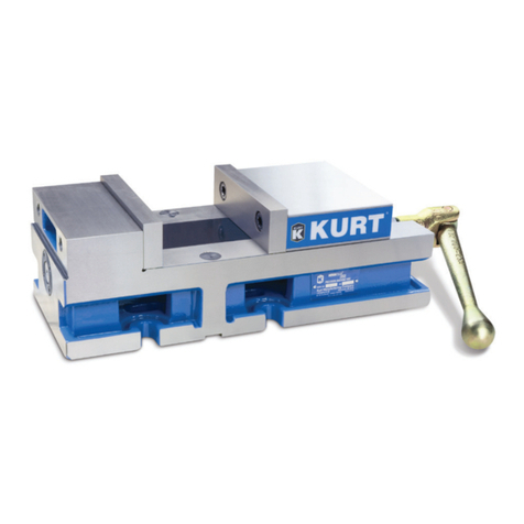
Kurt HDL6 User manual

HDL(M)6 Nut/Screw Assembly
Remove, repair, and reassemble the nut and screw assembly in your HDL
series double lock vise.
In these instructions when we refer to the “front” of the vise or nut/screw
assembly, we mean the end that has the hex for the handle and is closest to
the operator. The end that is farthest from the operator is considered the
“rear”.
(Numbers in parentheses reference the mechanical drawing on the last page.)
Removing the nut and screw assembly from your vise
1.
Remove the rear moveable jaw from your vise.
2.
Remove the button head cap screw (#28) from the front end of the
vise body.
3.
Place a spacer block between the stationary jaw and the front
moveable of the vise. Place your handle on the hex end of the lead
screw (#7) and turn clockwise to draw the jaws together. As the front
jaw tightens on the block, continue turning. This will push the holding
block (#17) out of the vises center channel. A small rubber springpre-
load block (#34) and steel wedge friction clamp (#33) will fall out of
the holding block (#17) when it is clear of the vise.
4.
Once the holding block (#17) is free of the vise remove your spacer
block, the remaining moveable jaw, and the stationary jaw.
5.
Remove the chip guards (#46 & 47)
6.
Slide the nut and screw assembly toward you until it is all the wayout
of the vise body.
Disassembling the nut and screw assembly
1.
Remove the small spiral retaining ring (#6) from the rear nut.
This ring has a small tab on the end of it that can be hooked and pried
inward then lifted up until it is out of the snap ring groove.
2.
Unscrew and remove the rear nut (#4) from the screw (#7) byholding
on to the rear nut and turning the hex on the lead screw in a counter
clockwise direction.
As you unscrew the nut from the lead screw a rubber seal (#5) will
come out of the nut. This was being held in by the retaining
ring that was removed in the previous step.
3.
Hold on to the front nut and turn the screw in a clockwise direction
until you can see the small spiral retaining ring (#16) in the back of
the front nut. Remove this spiral retaining ring the same way you did
with the one in the rear nut in step #1.
4.
Once the spiral retaining ring (#16) has been removed continue to turn
the screw in a clockwise direction until the nut (#14) is free from the
threads on the clutch (#13) and gently slide the nut off the end of the
screw. There is an o-ring that will come out of the nut and remain on
the clutch when you remove the nut. The spiral retaining ring you
removed was holding this o-ring in the nut.
5.
Stand the screw (#7) up on the hex end and using an external snap
ring pliers remove the external snap ring (#10) from the screw.
6.
Place the clutch (#13) in a vise with non marring jaws or wrap a rag
around the clutch to prevent the clutch from being damaged. Apply
only enough pressure to prevent the clutch from turning when you
turn the lead screw using the hex handle. Do not apply so much
pressure that you crush or oblong the clutch. Turn the lead screw
clockwise until you feel the pin (#12) being depressed and popping
out of the drive notch. Continue turning the screw clockwise 180
degrees. If the nut and screw assembly has a pin that has been over
traveled it will be resting in the ramped slot in the clutch. You will
need to turn the screw counterclockwise to release the pin from the
over travel notch. Then turn the screw 180 degrees in a counter
clockwise direction.
7.
Wearing gloves or wrapping a rag around the clutch, firmly grasp the
clutch and tap the threaded end of the lead screw on a soft, non
marring surface until the clutch spacer starts to slide off the screw.
When the clutch reaches the area where the pin (#12) and the springs
(#11) are contained by the clutch sleeve hold a rag or your hand over
that area so the pin and springs don’t fly out. Continue to slide the
clutch sleeve down and remove it from the lead screw. If your visehas
built up excessive grit and chips it may take a few hard blows to get
the clutch off the screw.
8.
If the pin and springs are still in the screw remove them at this time.
9.
Slide the holding block assembly (#17) down and off the threaded end
of the lead screw. If the holding block binds in the area of the drive
slot use a file to smooth out any ridges on the slot edge.
Disassembling the holding block
1.
Remove set screw (#25) and set aside
2.
Using a spanner wrench turn the threaded collar (#23) counter
clockwise and remove it from the holding block.
3.
Turn the holding block upside down and gently tap it until remaining
items slide out of holding block. Remaining items will be the thrust
washers (#19) 3 each, thrust bearing (#20) 1 each, collar (#22) 1 each,
spring (#21) 6 each.
Reassembly of the holding block
1.
Place a new o-ring (#18) in the holding block (#17)
2.
Place a new o-ring (#24) in the threaded collar (#23)
3.
Place holding block (#17) on a flat surface with the threaded end up.
4.
Place the following parts in the holding block in the order listed
a.
Thrust bearing washer (#19)
b.
Thrust bearing (#20) Coat with a high grade grease
c.
Thrust bearing washer (#19)
d.
Collar (#22)
e.
Six compression springs (#21) Placed in the holes of the collar
f.
Thrust bearing washer (#19)
5.
Place the threaded collar (#23) on top and compress the springs
while threading the collar into the holding block. The threaded
collar has two holes for the spanner wrench and two half moon slots ¾
of the way down the side making an intermittent thread. Looking
through the tapped hole where the set screw was (#25), continue to
screw the collar into the holding block until you can see one of the
slots appear. Watching the slots through the threaded hole, continue to
thread the collar into the holding block ½ turn at a time until the last
thread on the collar before the slot is past the set screw hole. You
should only be able to see the slot in the collar.
6.
Place set screw (#25) in the threaded hole of the collar and tighten.
Then back off the set screw and tighten until it is snug.
Over tightening of this set screw will deform the collar and cause your
vise screw to bind during use.
Reassembling the nut and screw assembly
1.
Stand the screw on the hex end. Apply a thin coat of oil in the slot that
holds the springs (#11) and the pin (#12) and down the length of the
screw to the shoulder on the hex end
2.
Place the holding block on the threaded end of the screw with the
threaded collar side facing towards the hex end of the screw. Slide the
holding block all the way down to the shoulder of the screw.
3.
Slide a new o-ring (#15) onto the smooth end of the clutch
4.
Place a new spiral retaining ring (#16) onto the smooth end of the
clutch after the o-ring
5.
Place clutch (#13) on the screw, smooth end first, with the two
notches on the inside of the clutch facing downward opposite the
drive slot. Slide the clutch down the screw, stopping just before the
slot. Do not cover the slot with the clutch.
6.
Place three springs (#11) into the slot standing them up vertically, one
spring in each hole
7.
Lay the pin (#12) on top of the 3 springs holding them in place with
your hand. Use a pliers to compress and hold down the pin while you
slide the clutch over the top of the pin.
8.
When the clutch is on far enough to hold the pin in place, grasp the
clutch with a rag or gloved hand and slide it all the way down, seating
it in the mating bore of the holding block (#17). There is a snap ring
groove on the screw that will be visible when the clutch is in proper
position.
9.
Stand the screw up with hex end on your work surface. Hold the
screw with one hand and turn the clutch counter clockwise until the
pin drops into the notch on the inside diameter of the clutch. Thereare
two notches on the inside diameter of the clutch. One has a ramp and
the other does not. The pin must me in the notch that does not have
the ramp
10.
Using an external snap ring pliers, slide the snap ring (#10) down the
length of screw and snap into place in the groove on the screw. Snap
rings have one side that the edges will feel sharp and the other side
the edges will feel rounded. The sharp side of the edges should be
facing away from the clutch when installed. If the snap ring is
installed backwards. The snap ring will have a tendency to pop out of
its groove.
11.
Place a small amount of grease in the front nut (#14) then slide it on
the screw with the plunger (#40) facing the hex end of the screw until
it reaches the threads on the clutch. Thread the nut onto the clutch in a
counter clock wise direction until all the threads of the clutch are
inside the nut. The threads in the front nut are left handed.
12.
Stand the screw on a soft surface with the threaded end down.
Use a small screw driver to push the o-ring (#15) down into the
recess of the nut.
13.
Slide the spiral retaining ring down using a small screw
Driver. Spread the end that is nearest the nut apart and push the
leading edge into the groove on the inside diameter of the nut. Follow
the retaining ring around with the screw driver (in the same fashion as
threading a nut onto a bolt) until it snaps into the groove. Push the
snap ring out from the inside to make sure it is seated in the groove in
the nut.
14.
Using the vise handle turn the screw counter clockwise while
holding the front nut until the nut comes to a stop near theholding
block. There should be a small gap between the front nut and holding
block.
15.
Spin the holding block counter clockwise until the set screw is
facing straight up and in line with the top of the nut.
16.
Place spiral retaining ring (#6) on the threaded end of the screw
and slide it down towards the front nut.
17.
Take seal (#5) and using a utility knife cut a slit in the diameter
and place the seal around the diameter of the screw just behind
the threads at the end of the screw. This seal is very stiff. Cuttinga
slit in it allows you to slip it around the screw without having to push
it on over the threads and possibly damaging the seal.
18.
Place a small amount of grease in the rear nut (#4)
and thread it onto the screw in a clockwise direction
until the threads are fully engaged in the nut.
19.
Stand the screw and nut up on the rear nut. Slide the seal (#5)
down and use a small screw driver to push the seal into the relief
of the rear nut until it sits below the snap ring groove in the nut.
20.
Slide the spiral retaining ring down and thread it into the
retaining ring groove of the nut in the same manner as you did in
step 12 for the front nut.
21.
Turn the rear nut counter clock wise until you can feel resistance.
Do not force the nut any further than the point you feelresistance
or it will force the seal and retainer out of place.
22.
Turn the nut back until the front and rear nut are in line with
each other. This sets the timing of the front and rear nut.
23.
Slide the nut and screw assembly back into the vise until it reaches
the holding block assembly.
24.
Make sure that the set screw in the holding block is facing up.
Place the rubber spring pre-load block (#34) and steel wedge friction
clamp (#33) into the space on the right side of the holding block
(#17). If these parts show excessive ware, or are deformed you may
want to replace them.
25.
Place the stationary jaw back on your vise and tighten
26.Place the rear moveable on your vise and snap into place
27.
Place the handle on the hex of the screw and turn clockwise
until the rear moveable closes tight against the stationary
jaw. Continue to tighten your vise until it draws the holding block
containing the friction clamp into the vise. You will feel some
resistance until the friction block slides into the vise. If the friction
clamp will not slide into the vise, it may be necessary to use a
hammer and punch to lightly tap on the friction clamp while
maintaining pressure on the screw.
28.
Once the holding block has slid into the vise body you can place
your front moveable jaw on the vise and snap into place.
29.
Continue to close the jaws of the vise until both the front and rear
moveable contact the stationary.
30.
Replace the button head cap screw (#28)
31.Your vise is now ready for use.

Other manuals for HDL6

1

This manual suits for next models

1

Other Kurt Tools manuals

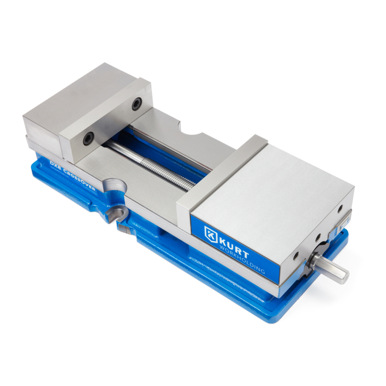
Kurt CROSSOVER DX6H Instruction Manual

Kurt

Kurt CROSSOVER DX6H Instruction Manual

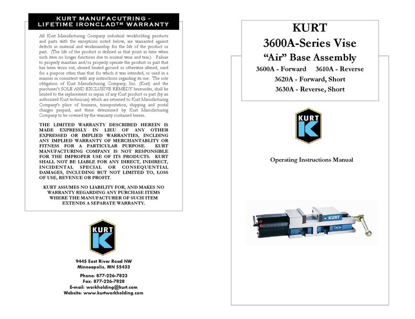
Kurt 3600A Series Instruction Manual

Kurt

Kurt 3600A Series Instruction Manual

Kurt CROSSOVER ANGLOCK VISE DX6 Instruction Manual

Kurt

Kurt CROSSOVER ANGLOCK VISE DX6 Instruction Manual

Kurt HDL6 User manual

Kurt

Kurt HDL6 User manual

Kurt D688 AngLock Vise Base Assembly Instruction Manual

Kurt

Kurt D688 AngLock Vise Base Assembly Instruction Manual

Kurt 360PWS Instruction Manual

Kurt

Kurt 360PWS Instruction Manual

Kurt DL640 Original operating instructions

Kurt

Kurt DL640 Original operating instructions

Kurt DTR10 Instruction Manual

Kurt

Kurt DTR10 Instruction Manual

Kurt CROSSOVER ANGLOCK VISE DX8 Instruction Manual

Kurt

Kurt CROSSOVER ANGLOCK VISE DX8 Instruction Manual

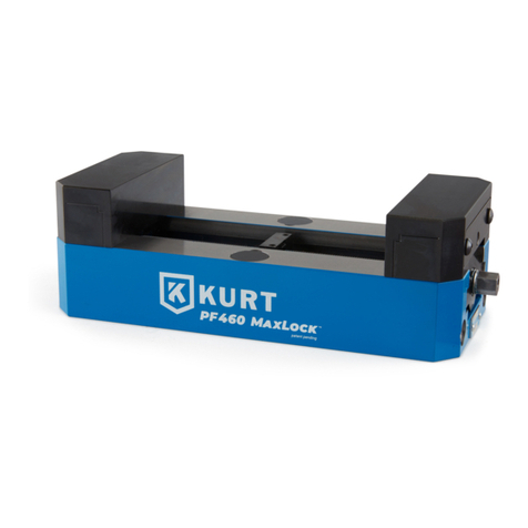
Kurt PF Series Instruction Manual

Kurt

Kurt PF Series Instruction Manual

Kurt VERSATILELOCK 3600H Instruction Manual

Kurt

Kurt VERSATILELOCK 3600H Instruction Manual

Kurt DTR20 Instruction Manual

Kurt

Kurt DTR20 Instruction Manual

Kurt VERSATILELOCK 3410V Instruction Manual

Kurt

Kurt VERSATILELOCK 3410V Instruction Manual

Kurt 3800V Series Instruction Manual

Kurt

Kurt 3800V Series Instruction Manual

Kurt DT20 User manual

Kurt

Kurt DT20 User manual

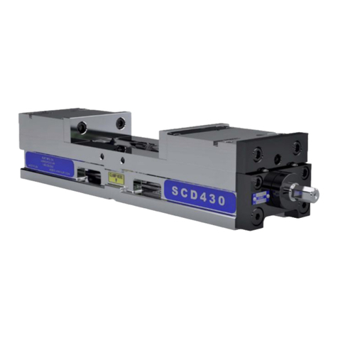
Kurt SCD430 Instruction Manual

Kurt

Kurt SCD430 Instruction Manual

Kurt 3600V Series User manual

Kurt

Kurt 3600V Series User manual

Popular Tools manuals by other brands

Sealey DH01.V3 quick start guide

Sealey

Sealey DH01.V3 quick start guide

Beta 1924B instructions

Beta

Beta 1924B instructions

Duralast 80-375 Operating instructions and parts manual

Duralast

Duralast 80-375 Operating instructions and parts manual

pela tools 511054 manual

pela tools

pela tools 511054 manual

Chicago Pneumatic CP 0016 Safety and operating instructions

Chicago Pneumatic

Chicago Pneumatic CP 0016 Safety and operating instructions

Maximum 058-9365-2 instruction manual

Maximum

Maximum 058-9365-2 instruction manual

The Cool Tool PLAYMAT manual

The Cool Tool

The Cool Tool PLAYMAT manual

Vivosun HR-20 instruction manual

Vivosun

Vivosun HR-20 instruction manual

ATD Tools ATD-5831 instruction manual

ATD Tools

ATD Tools ATD-5831 instruction manual

RIDGID SeeSnake microDRAIN APX Operator's manual

RIDGID

RIDGID SeeSnake microDRAIN APX Operator's manual

Sealey SA40 instructions

Sealey

Sealey SA40 instructions

SMC Networks VMG Operation manual

SMC Networks

SMC Networks VMG Operation manual

Performance Tool W2007 owner's manual

Performance Tool

Performance Tool W2007 owner's manual

Truper ENNE-160 manual

Truper

Truper ENNE-160 manual

AG SHIELD 12" CROSS AUGER Operator's manual

AG SHIELD

AG SHIELD 12" CROSS AUGER Operator's manual

Bostitch IC50-2-E Original instructions

Bostitch

Bostitch IC50-2-E Original instructions

VEVOR FSH-Y10 user manual

VEVOR

VEVOR FSH-Y10 user manual

Sonex Aircraft 883 Pilot operating handbook

Sonex Aircraft

Sonex Aircraft 883 Pilot operating handbook

manuals.online logo
manuals.online logoBrands
  • About & Mission
  • Contact us
  • Privacy Policy
  • Terms and Conditions

Copyright 2025 Manuals.Online. All Rights Reserved.