Kurz B-Series User manual

Operations Guide for B-Series Flow Meters
368042E

KurzB‐SeriesOperationsGuideii
Copyrights and Trademarks
Copyright©2020KurzInstruments,Inc.
Allrightsreserved.
Nopartofthispublicationmaybereproducedortransmittedinanyformorbyanymeans,electronicormechanical,
includingphotocopying,recording,orbyanyinformationstorageandretrievalsystemwithoutexpresswritten
permissionfromKurzInstruments,Inc.,2411GardenRoad,Monterey,California93940;Phone:831‐646‐5911,
Fax: 831‐646‐8901,orwww.kurzinstruments.com
Thematerialinthismanualisforinformationonlyandissubjecttochangewithoutnotice.Everyreasonableefforthas
beenmadetoensurethattheinformationinthismanualiscompleteandaccurate.KurzInstruments,Inc.makesno
representationsorwarrantiesofanykindconcerningthecontentsofthispublication,andthereforeassumesno
liability,loss,ordamagesresultingfromuse,errors,oromissionsinthispublicationorfromtheuseoftheinformation
containedherein.KurzInstruments,Inc.,isnotresponsibleforprintingorclericalerrors.
KurzInstruments,Inc.,reservestherighttomakeengineeringchanges,productimprovements,andproductdesign
changeswithoutreservationandwithoutnotificationtoitsusers.ConsultyourKurzInstruments,Inc.representativeor
afactoryapplicationsengineerforinformationregardingcurrentspecifications.
KurzInstruments,Inc.assumesnoliabilityfordamagesorinjuries(consequentialorotherwise)causedbytheimproper
useand/orimproperinstallationofthisproductorwherethisproductisusedinanyapplicationotherthanwhatitwas
designedforandintended.KurzInstruments,Inc.expresslydeniesanyresponsibilityifthisproducthasbeenmodified
withoutKurzInstruments,Inc.writtenapprovalorifthisproducthasbeensubjectedtounusualphysicalorelectrical
stress,oriftheoriginalidentificationmarkshavebeenremovedoraltered.
EquipmentsoldbyKurzInstruments,Inc.isnotintendedforuseinconnectionwithanynuclearfacilityoractivity
unlessspecificallysoldforsuchapplicationsandspecificconditionsforsuchusagearedetailed.Iftheequipmentis
usedinanuclearfacilityoractivitywithoutsupportingquotation,KurzInstruments,Inc.disclaimsallliabilityforany
damage,injury,orcontamination,andthebuyershallindemnifyandholdKurzInstruments,Inc.,itsofficers,agents,
employees,successors,assigns,andcustomers,whetherdirectorindirect,harmlessfromandagainstanyandall
losses,damages,orexpensesofwhateverformandnature(includingattorneysfeesandothercostsofdefendingany
action)whichthey,oranyofthem,maysustainorincur,whetherasaresultofbreachofcontract,warranty,tort
(includingnegligence),strictliabilityorothertheoriesoflaw,byreasonofsuchuse.
TheKurzlogoisatrademarkofKurzInstrument,Inc.,registeredintheU.S.andothercountries.UseoftheKurzlogo
forcommercialpurposeswithoutthepriorwrittenconsentofKurzInstruments,Inc.mayconstitutetrademark
infringementinviolationoffederalandstatelaws.MetalClad,B‐Series,Series410FTB,Series454FTB,Series454FTB‐
WGF,Series504FTB,Series 534FTB,andK‐BAR2000B,K‐BAR200B‐WGF,WetGas,Series155MassFlowComputer,and
Series255FlowAveragingTransmitteraretrademarksofKurzInstruments,Inc.
Othercompanyandproductnamesmentionedhereinaretrademarksoftheirrespectiveowners.Mentionofthird‐
partyproductsisforinformationalpurposesonlyandconstitutesneitheranendorsementnorarecommendation.
Kurz Instruments,Inc.,assumesnoresponsibilitywithregardtotheperformanceoruseoftheseproducts.
KurzInstrumentsInc. KurzTechnicalSupport
2411GardenRoad CustomerService
Monterey,CA93940 800‐424‐7356(tollfree)
831‐646‐5911(main) www.KurzInstruments.com
831‐646‐8901(fax) Service@KurzInstruments.com

KurzB‐SeriesOperationsGuideiii
List of Tables
Chapter1
B‐SeriesFlowMeterModes & Menus
Table 1‐1. ProgramMode.......................................................................... 1‐8
Table 1‐2. LogMode.................................................................................. 1‐15
Table 1‐3. ExtendedUtilitiesMode............................................................ 1‐17
Table 1‐4. Keyboard‐KeypadEquivalentKeys............................................ 1‐18
Chapter2
B‐SeriesFlowMeterDisplay Mode Options
Table 2‐1. DisplayMode............................................................................ 2‐3
Chapter3
Program ModeBasic Setup
Table 3‐1. ProgramMode‐BasicSetup..................................................... 3‐3
Chapter4
Program ModeAdvanced Setup
Table 4‐1. 4‐20mAOutputFunctions........................................................ 4‐12
Table 4‐2. Temporary4‐20mAProcessMeasurementOverride.............. 4‐12
Table 4‐3. 4‐20mAOutputFunctions........................................................ 4‐14
Table 4‐4. Temporary4‐20mAProcessMeasurementOverride.............. 4‐14
Table 4‐5. 4‐20mARangesforPredefinedCalibrationCurves................... 4‐42
Table 4‐6. ModbusCommunicationParameters....................................... 4‐47
Chapter5
Extended Utilities Mode
Table 5‐1. ExtendedUtilityMode(DriftOptions)...................................... 5‐2
Chapter6
Flow Meter Configuration
Table 6‐1. Summaryofflowcontrollercapabilities................................... 6‐4

KurzB‐SeriesOperationsGuide v
Table of Contents
Preface ..................................................................................... x
BeforeYouBegin............................................................................................ xi
UsingthisManual........................................................................................... xi
ManualConventions....................................................................................... xii
SystemRequirements..................................................................................... xii
SoftwareRequirements.................................................................................. v‐xiii
Chapter1
B‐SeriesFlowMeterModes & Menus...................................... 1‐1
Overview......................................................................................................... 1‐1
FlowMeterUserInterface.............................................................................. 1‐2
MeterKeypad.......................................................................................... 1‐3
FlowMeterDisplayScreen...................................................................... 1‐4
BootMode...................................................................................................... 1‐5
RunMode....................................................................................................... 1‐6
ProgramMode................................................................................................ 1‐7
LogMode........................................................................................................ 1‐15
EventLog................................................................................................. 1‐15
Min/MaxLog........................................................................................... 1‐16
TrendLog................................................................................................. 1‐16
ConfigLog................................................................................................ 1‐16
RunDataLog............................................................................................ 1‐17
ExtendedUtilitiesMode................................................................................. 1‐17
RemoteTerminalAccess................................................................................. 1‐18
QuickReferenceCard..................................................................................... 1‐18
Chapter2
B‐SeriesFlowMeterDisplay Mode Options............................. 2‐1
Overview......................................................................................................... 2‐1
DisplayMode.................................................................................................. 2‐3
Option1—BasicSetup.................................................................................. 2‐5
Option2—LowFlowCutoff........................................................................... 2‐8
Option3—SensorBlockageCorrectionFactor............................................. 2‐9
Option5—AnalogOutput1.......................................................................... 2‐10
Option8—Relays.......................................................................................... 2‐11

KurzB‐SeriesOperationsGuidevi
Option10—NE‐43Alarm.............................................................................. 2‐12
Option13—CalibrationData........................................................................ 2‐13
Option15—VariableFlowCorrectionData.................................................. 2‐16
Option23—DriftCheck................................................................................ 2‐17
Option27—WGFVaporCorrectionFactor.................................................. 2‐19
Option32—FactorySensorSetup................................................................ 2‐20
Option41—ExternalInputCurrent.............................................................. 2‐22
ViewingtheExternalAnalogInputforShiftingGases............................ 2‐22
ViewingtheExternalAnalogInputforMultipleGasCurves................... 2‐23
Option42—FlowData.................................................................................. 2‐24
Option43—TemperatureData.................................................................... 2‐26
Option44—InputVoltage............................................................................ 2‐27
Option45—SensorOutput........................................................................... 2‐28
Option47—ElectronicsTemperature.......................................................... 2‐29
Option48—SensorLeakage......................................................................... 2‐29
Option49—MeterEventCode..................................................................... 2‐30
Option50—FirmwareVersion..................................................................... 2‐30
Chapter3
Program ModeBasic Setup..................................................... 3‐1
Overview........................................................................................................ 3‐1
ProgramMode—BasicSetup....................................................................... 3‐2
BasicSetupParameters.................................................................................. 3‐3
BasicFlowMeterSetup.................................................................................. 3‐5
Chapter4
Program ModeAdvanced Setup............................................... 4‐1
Overview........................................................................................................ 4‐1
ProgramMode—AdvancedSetup................................................................ 4‐3
Option1—BasicSetup.......................................................................... 4‐4
Option2—LowFlowCutoff................................................................... 4‐8
Option3—FlowCorrectionFactorandFlowTimeConstant................ 4‐9
Option4—FlowTotalizerReset............................................................ 4‐10
Option5—SettingUpAnalogOutput1................................................. 4‐12
Option6—SettingUpAnalogOutput2................................................. 4‐14
Option7—SettingUpRunModeDisplay.............................................. 4‐16
StaticVariables................................................................................ 4‐17
ScrolledVariables............................................................................. 4‐18
Option8—SettingUpRelays................................................................. 4‐19
Option9—SettingUpAlarms................................................................ 4‐21
Option10—SettingUptheNE‐43Alarm............................................... 4‐24

KurzB‐SeriesOperationsGuidevii
Option11—SettingUpaPulseOutput................................................. 4‐25
Option12—SettingUptheSensorPurge............................................. 4‐26
Option13—CalibrationData................................................................ 4‐28
Option14—Recalibratingthe4‐20mAOutputs.................................... 4‐32
Option15—VariableFlowCorrection................................................... 4‐34
Option16—RemoteCorrectionFactor................................................. 4‐35
Option17—ConfiguredforShiftingGases............................................ 4‐37
ShiftingGasComposition................................................................ 4‐37
ChangingtheShiftingGasCompositionManually.......................... 4‐38
ChangingtheShiftingGasCompositionAutomatically
ThroughtheExternalInput............................................................. 4‐39
ViewingtheExternalAnalogInputforShiftingGases..................... 4‐41
TroubleshootingShiftingGasComposition..................................... 4‐41
Option17—ConfiguredforMultipleGases.......................................... 4‐42
MultipleGasCalibrations................................................................ 4‐42
ChangingtoAnotherGasCurveManually...................................... 4‐43
ChangingtoAnotherGasCurveAutomaticallyThrough
theExternalInput............................................................................ 4‐44
ViewingtheExternalAnalogInputforMultipleGasCurves........... 4‐45
TroubleshootingMultipleGasCurves............................................. 4‐45
Option18—SettingUpDataLogging.................................................... 4‐46
Option19—SettingUpModbusCommunication................................. 4‐47
Option20—SettingUpExternalInput.................................................. 4‐49
VMReference.................................................................................. 4‐50
CalibrationDataSW........................................................................ 4‐51
RemoteCF....................................................................................... 4‐51
PurgeCommand.............................................................................. 4‐52
Option21—SettingUpPIDData........................................................... 4‐53
Option22—ManualPIDAdjustments................................................... 4‐56
ManuallyTuningAPIDLoop............................................................ 4‐57
Option23—DriftCheck......................................................................... 4‐59
Option24—BasicandAdvancedPasswords......................................... 4‐61
Option25—EEPROMUpdate................................................................ 4‐62
Option26—SettingaDelayforBootupOutput.................................... 4‐63
Option27—WGFVaporCorrectionFactor .......................................... 4‐64
Option28—FrequencyOutputScale ................................................... 4‐65

KurzB‐SeriesOperationsGuideviii
Chapter5
Extended Utilities Mode.......................................................... 5‐1
Overview........................................................................................................ 5‐1
ExtendedUtilitiesModeOptions................................................................... 5‐2
Option1—ZeroDriftCheck.......................................................................... 5‐4
Option2—MidDriftCheck........................................................................... 5‐5
Option3—SpanDriftCheck......................................................................... 5‐6
Option4—CycleDriftCheck......................................................................... 5‐7
Option5—ResettingFlowTotalizer............................................................. 5‐8
Chapter6
Flow Meter Configuration....................................................... 6‐1
Overview........................................................................................................ 6‐1
SpecifyingDriftCheckTriggers....................................................................... 6‐2
Specified‐TimeIntervalDriftCheck........................................................ 6‐2
ExternalDigitalInput.............................................................................. 6‐2
ModbusProtocolWriteCoilCommand.................................................. 6‐3
ModbusStatusRegisters........................................................................ 6‐3
HARTInterface........................................................................................ 6‐4
ConfiguringtheBuilt‐InFlowController........................................................ 6‐4
SettingUptheFlowController............................................................... 6‐5
SettingUpAPID...................................................................................... 6‐5
CleaningASensor&ThePurgeController..................................................... 6‐6
UsingtheIntegratedPurgeController.................................................... 6‐6
WiringforthePurgeController.............................................................. 6‐7
AssigningaRelaytothePurgeFunction................................................. 6‐8
OperatingandMonitoringPurgeCleaningUsingModbus .................... 6‐8
OperatingandMonitoringPurgeCleaningUsingHART......................... 6‐8
AutomaticallyTriggeringDriftCheckandPurge .................................... 6‐9

KurzB‐SeriesOperationsGuide ix
Preface

KurzB‐SeriesOperationsGuidex
Before You Begin
Important Thedevicewarrantyisvoidifthedeviceisnotinstalledinaccordancewiththe
specifiedinstallationrequirements.Readandthoroughlyunderstandthe
installationrequirementsbeforeattemptingtoinstallthedevice.Ifyouhave
anyquestions,contactyourKurzcustomerservicerepresentativebefore
attemptinginstallation.
Using this Manual
KurzInstruments,Inc.,documentationincludesmanuals,productliterature,AdobeAcrobatPDF
files,andapplicationonlineHelpfiles.TheKurzInstrumentsCDcontainsalltheavailable
documentationfiles.ToreadPDFfiles,downloadthefreeAdobeAcrobatReaderfrom
www.adobe.com.
TheKurzInstrumentsWebsiteprovidesadditionalinformation:
•WorldWideWeb:www.KurzInstruments.com
•Email:Service@KurzInstruments.com
•Documentationlinkstothemostcurrentmanualsandliterature
Youcanaccessdevicesupportinthefollowingways:
•Main:831‐646‐5911
•Phone:800‐424‐7356
•Fax:831‐646‐8901

KurzB‐SeriesOperationsGuide xi
Manual Conventions
ThefollowingtablelistsconventionsusedintheKurzInstruments,Inc.,documentation,andgives
anexampleofhoweachconventionisapplied.
System Requirements
TheB‐SeriesusetheXMODEMcommunicationprotocolviaUSBcable,ortheMODBUSprotocol
overRS‐485orMODBUSTCP/IPinterface.TheKurzUSBdevicedriverorFTDIUSBdevicedriver
mustbeinstalledbeforeattemptingtoconnectacomputerwithaB‐SeriesdeviceviaaUSBcable.
TheB‐Seriesdevicesrequire:
•Ashieldedtwisted‐paircableforModbusRTU.
•FortheXMODEMprotocol,aUSBTypeA‐to‐miniBcable.
Note TheKurzUSBdevicedriverorFTDIUSBdevicedrivermustbeinstalled
beforeattemptingtoconnectacomputerwithaB‐Seriesdeviceviaa
USBcable.Thesedriversareaninstallationoptionduringtheinstallof
KzComm.
•FortheModbusTCP/IPprotocol,anEthernetcabletoaModbusTCP/IPtoRS‐485gateway.
Table1.Conventionsusedinthismanual
Convention ForExample
Texttype,click,orselect(forexample,
fieldnames,menus,andcommands)
areshowninbold.
ChecktheConfigurationFilecheckbox.
Textappearinginadisplayorwindowis
shownincourier.
PRESS ENTER TO
SET METER DATA
Anarrow(→)isusedtoseparatea
menunamefromitsmenucommand.
SelectStart→AllPrograms→KurzInstruments→KzComm.
Simplifieddirectorystructuresandpath
namesareusedinexamples.Your
foldernamesmaybedifferent.
ProgramsFiles\KurzInstruments\KzComm.

KurzB‐SeriesOperationsGuidexii
Software Requirements
KzCommissupportedonWindowsXP,WindowsVista,Windows7,Windows8,andWindows 10.
All platformsrequireup‐to‐dateservicepacks.
Note OnWindowsVista,downloadingtheTrendLoghasinfrequentlycaused
theoperatingsystemtofreeze(noscreenactivity).Restartthecomputer
asdescribedinyourcomputerhardwaremanual.
Basiccomputerknowledgeisnecessaryforcopyingandmovingfiles,navigatingfilestructures,
identifyingfiletypes,andinstallingapplications.
TheKurzUSBdevicedriverorFTDIUSBdevicedrivermustbeinstalledbeforeattemptingto
connectacomputerwithaB‐SeriesdeviceviaaUSBcable.Bothdriversareavailableduringthe
KzComminstallation,ontheKurzcustomerCDintheUSBDeviceDriverfolder,andontheKurz
website(kurzinstruments.com).TheFTDIUSBdriverisa64‐bitvirtualCOMport(VCP)driver
availablefromtheFTDIChipwebsite(ftdichip.com).

KurzB‐SeriesOperationsGuide xiii
List of Figures
Chapter1
B‐SeriesFlowMeterModes & Menus
Figure 1‐1. Flowmeteruserinterface......................................................... 1‐2
Figure 1‐2. Flowmeterdisplayscreen........................................................ 1‐4
Figure 1‐3. Menusuboptionindicator ....................................................... 1‐4
Figure 1‐4. Userinterfacequickreferencecard.......................................... 1‐19
Chapter4
Program ModeAdvanced Setup
Figure 4‐1. 4‐20mAoperationwiththeNE‐43alarm................................. 4‐24
Figure 4‐2. Examplesofsystemresponses‐Increasevs.Decrease............ 4‐57
Figure 4‐3. Examplesofsystemresponses‐Decreasevs.Increase............ 4‐58
Figure 4‐4. Examplesofsystemresponses‐TunedCorrectly..................... 4‐58
Chapter6
Flow Meter Configuration
Figure 6‐1. Maskedpurgeblast................................................................... 6‐7

KurzB‐SeriesOperationsGuide 1–1
Chapter 1
B-Series Flow Meter
Modes & Menus
Overview
ThissectiondescribestheuserinterfacefortheB‐Seriesflowmeterandprovidesthemenu
structureforeachmode:
•Boot‐Upmode
•Runmode
•Displaymode
•Programmode
•Logmode
•ExtendedUtilitiesmode
Important Alloptionparametersandexamplesusesamplevaluesandmeasurement
units.Thevaluesandmeasurementunitsyouseereflecttheconfigurationof
theflowmeter.
Thischapterisintendedforusersaccessingtheflowmetermenususingthelocalkeypadand
display.However,themenusandcommandsremainthesameevenifyouareusingaterminal
emulatorwithablinddevice.

KurzB‐SeriesOperationsGuide1–2
B‐SeriesFlowMeterModes & Menus
Flow Meter User Interface
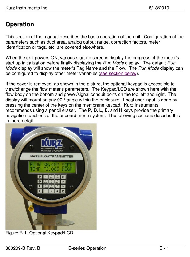
Toaccesstheflowmeteruserinterface,unscrewtheenclosurelid.
Theflowmeteruserinterface(Figure 1‐1)includesadisplayscreenwithtworowsof16
charactersandakeypadwith20 keys(severalofwhichhavedualfunctions).Youmayneedtouse
asmall‐tippointingdevicetopressthekeys.
Figure 1‐1. Flowmeteruserinterface
Therearesixoperatingmodesforthemeter:
•Boot‐upmode
Occursduringapowercyclewhenthemeterperformsself‐testsfordiagnostics.
•Runmode
AninstalledmeterisnormallyinRunmodetomeasuretheflowandtemperatureof
theprocessgas.
•Displaymode
Aview‐onlyofthemeter’sconfigurationparameters.
•Programmode
Allowsyoutomakeconfigurationandparameterchangestothemeter.
•Logmode
Allowsyoutosendreportstothemeter’sserialport.
•ExtendedUtilitiesmode
Allowsaccesstoadvancedmeterfunctions.
ABC DEF
GHI JKL MNO
PQRS TUV WXYZ
123
456
789
P
D
H
0
L
C
E

KurzB‐SeriesOperationsGuide1–3
B‐SeriesFlowMeterModes & Menus
Meter Keypad
Thelargeletterkeysareusedfor:
•ThePkeyaccessesProgrammodeformakingconfigurationchangestothemeter.Thisisan
accesscode‐protectedmode.Italsoallowsyoutoacceptthecurrentparametervalueand
movetothenextparameter.
•TheDkeyaccessesDisplaymodeforaview‐onlyofthemeter’sconfigurationparameters.
Itcanalsobeusedasabackspacekey.
•TheLkeyaccessesLogmodeandsendsreportstothemeter’sUSBport.
•TheEkeyaccessesExtendedUtilitiesmodefortheadvancedfeaturesofthemeter.Thisis
anaccesscode‐protectedmode.TheEkeyisalsousedasanEnterkeyandtoacceptand
savechangesafterenteringdata.
•TheHkeyistheHomekeyusedforbackingoutofanymenu.PressHtobackuponelevel
orpressittwicetoreturntoRunmode.
•TheCkeyisusedtoclearadataentryfield.
Thealphanumerickeysincludenumbers0through9,withkeys2through9alsobeingusedfor
lettersAtoZ.Fordatafieldsthatacceptalphabeticdata,continuepressingthealphanumerickey
tocyclethroughtheletters.Forexample,ifyouwantedtoentertheletter“R,”youwouldpress
the7key,pressagainfor“P,”pressagainfor“Q,”andpressagainfor“R.”PresstheEkeytosave
theselectionandmovetothenextfield.
Thesymbolkeysare:
•Theuparrow()anddownarrow()keysareusedtoscrollthroughamenu.Thescroll
optionisavailablewhenthesymbol^vappears.
•Thebar(—)keyisusedforenteringnegativevaluesorahyphen.
•Thedot()keyisusedforenteringadecimalorperiod.
•Thearrow()keyoverlayingtheDkeybecomesabackspacekeyafteryouentera
mode.Itisusedfordeletingcharacterstotheleft.

KurzB‐SeriesOperationsGuide1–4
B‐SeriesFlowMeterModes & Menus
Thealphanumerickeysincludenumbers0through9,withkeys2through9alsobeingusedfor
lettersAtoZ.Fordatafieldsthatacceptalphabetic/numericstrings,continuepressingthekeyto
cyclethroughtheletters.Forexample,continuepressingthe7keytocyclethroughthe
charactersuntilyoureachR.ThenpresstheEkeytosavetheselectionandmovetothenext
field.Keys0and1providesymbols,includingaspace.
Thekeycharactermapisasfollows:
Flow Meter Display Screen
Therearetwowaystonavigatethroughthemenuoptions:
•MenuScrollallowsyoutosequentiallyscrollthrougheachmenuoption.
•QuickJumpallowsyoutojumpdirectlytoanoptionnumber.
Figure 1‐2. Flowmeterdisplayscreen
Whenmenusuboptionsareavailable,upanddownsymbolsappearattheendofthesecondline.
Figure 1‐3. Menusuboptionindicator
Key CharacterMap Key CharacterMap
00,<sp>,(,),+,,,<,>55,J,K,L
11,/,#,:,$,@,%,&66,M,N,O
22,A,B,C77,Q,R,S
33,D,E,F88,T,U,V
44,G,H,I99,W,X,Y, Z
1: M E N U S C R O L L
2: Q U I C K J U M P
^v

KurzB‐SeriesOperationsGuide1–5
B‐SeriesFlowMeterModes & Menus
Boot Mode
Thedeviceboottestverifiesthattheconfiguration,sensor,andwiringarevalid.Thelengthofthe
boot‐uptimevariesonwhetherthesensoriscoldorhotwhenthepowerisapplied.
TheB‐Seriesflowmetercanboot‐upandstartrespondingtohostcommunicationsorupdating
the4‐20mAoutputanddisplaywithinonesecondofrestarting/poweringup.However, theboot
sequencehastocompletetoguaranteetheintegrityofthedata,anditisgenerallyrecommended
towaitanadditional20secondsbeforeissuinganycommands.
Anearzeroflowratecancauseabootdelayupto2minutes,duringwhichtimethevelocity
sensormustcooloffsoitsresistancevaluecanbecheckedtoensuretherearenosensorfaults.
A highprocessvelocityduringboot‐upreducesthedelaybecausethehotsensorcancooldown
faster.
Whenthemeteristurnedonfromapower‐offstate,theNE‐43alarmissetuntilthesensorboot
processcompletes.Theflowandtemperaturewillthenindicatetheirpropervalues.
Whenyouboot‐up(poweron)theflowmeter,thedisplayprogressesthroughaseriesof
initializationindicators:
KURZ INSTRUMENTS
DISP DRIVER V4.X
CHECKING TYPE OF
CONNECTED SENSOR
WAIT PERFORMING
SENSOR LEAK TEST
KURZ INSTRUMENTS
SERIES MFT-B
FIRMWARE VERSION
MFT-B VER 2.XX
Note IfthedevicesupportsHartcommunication,anHappearsbeforethe
firmwareversionnumber.

KurzB‐SeriesOperationsGuide1–6
B‐SeriesFlowMeterModes & Menus
Oncebootupcompletes,theflowmeterautomaticallygoesintoRunmode.
Anerrormessageindicatestheunithasfailedboot‐uptestingduetoasensormismatch,wiring,
orotherproblem.
•Thedevicewillcyclethroughboottestingagainuntiltheissueisresolved
(forfirmware2.03andearlier).
Note DownloadingtheMin/Max,Event,andTrendlogsisnotpossibleuntil
boottestingcompletessuccessfully.
•YoucanforceabootexitbypressingtheCkey.
OncebootupcompletesyoucanstartdownloadingtheMin/Max,Event,andTrendlogs.
Run Mode
RunmodeisthenormaloperationalstateofthemeterafterBoot‐Upmode.Thedefaultdisplay
formatinRunmodeis“scrollall.’Thefollowingexampleshowstheflowmeter’stagnameand
flow:
TAG NATURAL GAS1
FLOW 0.0000 SCFM
Firmwareversion2.0andhigherallowsyoutodeterminehowprocessvariablesappearinRun
mode.SettingtheRunmodedisplayformatisavailablebyselectingoption7inProgrammode
withtheAdvancedaccesscode.YoucanalsoaccesstheRunmodedisplayformatbyselecting
option 1inProgrammodewiththeBasicaccesscode,althoughyoumustscrollthrough
the entirebasicsetup.SeeOption 7intheProgramMode—AdvancedAccesschapterformore
information.

KurzB‐SeriesOperationsGuide1–7
B‐SeriesFlowMeterModes & Menus
Program Mode
Programmodeallowsyoutomakeconfigurationandparameterchangestothemeter.Thisisan
accesscode‐protectedmode.Theaccesscodedeterminesthenumberoffunctionsyouhave
availablewhileinProgrammode.
•ThedefaultBasicaccesscodeis123456.Basicmetersetup(seeChapter3,“Program Mode
Basic Access”)isusedtoconfiguretheessentialflowmeterparameters(option1only):
—Metertagname
—Flowunits
—Flowarea
—Probedepth(forinsertionmeters)
—Analogoutputtypeandrange
—Runmodedisplaysetup
•ThedefaultAdvancedaccesscodeis654321.AdvancedSetup(seeChapter4,
“Program ModeAdvanced Setup”)isusedforchangingadvancedflowmeterparameters,
suchastimeconstantsandaccesscodes.
BeforemakinganyconfigurationchangesinProgrammode,itisimportanttoremember:
•AnyconfigurationchangesareautomaticallysavedtoEEPROMwhentheflowmeterexits
outofProgrammode.Therearenopromptstoconfirmchanges.
•Tobackoutofaseriesofmenus,continuetopressHforeachlevel(manualexit).
•Ifthereisnomenuactivityfor3minutes,thedisplayautomaticallyexitstoRunmode.Any
changesmadebeforetheauto‐exitaresavedtoEEPROM.
•Theconfigurationisretainedthroughflowmeterrebootsandpowercycles.
Important Youshouldnotmakeanychangestothemeterconfigurationwithouta
completeunderstandingoftheflowmeterparameters.Changingasetting
incorrectlycancausetheflowmetertomalfunction.
ToenterProgrammode:
1> PressP.
2> EntertheBasicaccesscodeortheAdvancedaccesscode.
3> PressE.
4> YoucanscrollthroughthemenuorquickjumptoanyoftheoptionsshowninTable 1‐1.
Note Notallparametersmayappearbasedontheflowmeterconfiguration.
Functionswith()supportHart.
Withinamenu,pressEorPtoscrollthroughthesubmenuoptionsunless
theup/downarrowsappear.
Inmostcases,whenyoureachtheendoftheparametersforamenu,the
promptautomaticallyreturnstothemainoptionmenu.Ininstances
whereyoucontinuetocyclethroughtheparameters,pressHtoexitthe
menu.
Other manuals for B-Series
1
This manual suits for next models
2
Table of contents
Other Kurz Measuring Instrument manuals