Kurz B-Series User manual

Complex Technology Made Simple
Technical Reference
Kurz Instruments, Inc.
2411 Garden Road
Monterey, CA 93940
800-424-7356 / 831-646-5911
www.kurzinstruments.com
B-Series Flow Meter
Operations Guide
368042A

B‐SeriesFlowMeterOperationsGuideii
Copyrights and Trademarks
Copyright©2013KurzInstruments,Inc.
Allrightsreserved.
Nopartofthispublicationmaybereproducedortransmittedinanyformorbyanymeans,electronicormechanical,
includingphotocopying,recording,orbyanyinformationstorageandretrievalsystemwithoutexpresswritten
permissionfromKurzInstruments,Inc.,2411GardenRoad,Monterey,California93940;Phone:831‐646‐5911,
Fax: 831‐646‐8901,orwww.kurzinstruments.com
Thematerialinthismanualisforinformationonlyandissubjecttochangewithoutnotice.Everyreasonableefforthas
beenmadetoensurethattheinformationinthismanualiscompleteandaccurate.KurzInstruments,Inc.makesno
representationsorwarrantiesofanykindconcerningthecontentsofthispublication,andthereforeassumesno
liability,loss,ordamagesresultingfromuse,errors,oromissionsinthispublicationorfromtheuseoftheinformation
containedherein.KurzInstruments,Inc.,isnotresponsibleforprintingorclericalerrors.
KurzInstruments,Inc.,reservestherighttomakeengineeringchanges,productimprovements,andproductdesign
changeswithoutreservationandwithoutnotificationtoitsusers.ConsultyourKurzInstruments,Inc.representativeor
afactoryapplicationsengineerforinformationregardingcurrentspecifications.
KurzInstruments,Inc.assumesnoliabilityfordamagesorinjuries(consequentialorotherwise)causedbytheimproper
useand/orimproperinstallationofthisproductorwherethisproductisusedinanyapplicationotherthanwhatitwas
designedforandintended.KurzInstruments,Inc.expresslydeniesanyresponsibilityifthisproducthasbeenmodified
withoutKurzInstruments,Inc.writtenapprovalorifthisproducthasbeensubjectedtounusualphysicalorelectrical
stress,oriftheoriginalidentificationmarkshavebeenremovedoraltered.
EquipmentsoldbyKurzInstruments,Inc.isnotintendedforuseinconnectionwithanynuclearfacilityoractivity
unlessspecificallysoldforsuchapplicationsandspecificconditionsforsuchusagearedetailed.Iftheequipmentis
usedinanuclearfacilityoractivitywithoutsupportingquotation,KurzInstruments,Inc.disclaimsallliabilityforany
damage,injury,orcontamination,andthebuyershallindemnifyandholdKurzInstruments,Inc.,itsofficers,agents,
employees,successors,assigns,andcustomers,whetherdirectorindirect,harmlessfromandagainstanyandall
losses,damages,orexpensesofwhateverformandnature(includingattorneysfeesandothercostsofdefendingany
action)whichthey,oranyofthem,maysustainorincur,whetherasaresultofbreachofcontract,warranty,tort
(includingnegligence),strictliabilityorothertheoriesoflaw,byreasonofsuchuse.
TheKurzlogoisatrademarkofKurzInstrument,Inc.,registeredintheU.S.andothercountries.UseoftheKurzlogo
forcommercialpurposeswithoutthepriorwrittenconsentofKurzInstruments,Inc.mayconstitutetrademark
infringementinviolationoffederalandstatelaws.MetalClad,SeriesMFTB,Series454FTB,Series504FTB,
Series 534FTB,andKBar‐2000BaretrademarksofKurzInstruments,Inc.
Othercompanyandproductnamesmentionedhereinaretrademarksoftheirrespectiveowners.Mentionofthird‐
partyproductsisforinformationalpurposesonlyandconstitutesneitheranendorsementnorarecommendation.
Kurz Instruments,Inc.,assumesnoresponsibilitywithregardtotheperformanceoruseoftheseproducts.
KurzInstrumentsInc. KurzTechnicalSupport
2411GardenRoad CustomerService
Monterey,CA93940 800‐424‐7356(tollfree)
831‐646‐5911(main) www.kurzinstruments.com
831‐646‐8901(fax) service@kurzinstruments.com

KurzB‐SeriesOperationsGuide iii
Table of Contents
Preface ..................................................................................... ix
BeforeYouBegin............................................................................................ x
UsingthisManual........................................................................................... x
ManualConventions....................................................................................... x
SystemRequirements..................................................................................... xi
SoftwareRequirements.................................................................................. xi
Chapter1
B‐SeriesFlowMeterModes&Menus...................................... 1‐1
Overview......................................................................................................... 1‐1
FlowMeterUserInterface.............................................................................. 1‐2
MeterKeypad.......................................................................................... 1‐3
FlowMeterDisplayScreen...................................................................... 1‐4
BootMode...................................................................................................... 1‐5
RunMode....................................................................................................... 1‐7
StaticVariables........................................................................................ 1‐7
ScrolledVariables.................................................................................... 1‐8
DisplayMode.................................................................................................. 1‐9
ProgramMode................................................................................................ 1‐11
LogMode........................................................................................................ 1‐20
EventLog................................................................................................. 1‐20
Min/MaxLog........................................................................................... 1‐20
TrendLog................................................................................................. 1‐21
ConfigLog................................................................................................ 1‐21
RunDataLog............................................................................................ 1‐21
ExtendedUtilitiesMode................................................................................. 1‐22
QuickReferenceCard..................................................................................... 1‐24

KurzB‐SeriesOperationsGuideiv
Chapter2
B‐SeriesFlowMeterMenu Applications................................... 2‐1
Overview........................................................................................................ 2‐1
DisplayMode—WetandDryFlowRates..................................................... 2‐2
ProgramMode—BasicAccess...................................................................... 2‐3
ProgramMode—AdvancedAccess.............................................................. 2‐7
EnablingDataLogging.................................................................................... 2‐8
TotalizingVolumeorMassFlow.................................................................... 2‐9
DeterminingAccuracyLimits.................................................................. 2‐9
ViewingtheTotalizedFlow..................................................................... 2‐9
ResettingtheFlowTotalizerValue......................................................... 2‐10
SettingUpAlarms.......................................................................................... 2‐12
AlarmSetup............................................................................................ 2‐12
SettingUptheRelayOutputforanAlarmFunction............................... 2‐14
SettingUpAnalogOutputChannels.............................................................. 2‐15
AnalogOutputSetupMenu.................................................................... 2‐16
PIDFlowControl..................................................................................... 2‐17
Zero‐Mid‐SpanDriftCheck...................................................................... 2‐17
NE‐43Alarms.......................................................................................... 2‐17
SettingRelayAssignments............................................................................. 2‐18
AssigninganAlarmtoaRelay................................................................. 2‐19
AssigningaPulsetoaRelay.................................................................... 2‐21
AssigningaPurgetoaRelay................................................................... 2‐22
PulseModeTotalizerOutput......................................................................... 2‐24
AssigningaTotalizerPulsetoaRelay..................................................... 2‐24
AccessingtheTotalizerPulseSetupMenu............................................. 2‐25
Built‐InZero‐Mid‐SpanDriftCheckCalibration.............................................. 2‐27
ConfiguringIndependentCalibrationforDriftCheck............................. 2‐27
SettingUpDriftCheck............................................................................. 2‐28
SpecifyingDriftCheckTriggers............................................................... 2‐29
Specified‐TimeIntervalDriftCheck ................................................ 2‐29
ExternalDigitalInput....................................................................... 2‐30
ExtendedUtilitiesModeOptions..................................................... 2‐30
ModbusProtocolWriteCoilCommand........................................... 2‐32
ModbusStatusRegisters ................................................................ 2‐32
HARTInterface........................................................................................ 2‐33
ConfiguringtheBuilt‐InFlowController........................................................ 2‐33
SettingUptheFlowController............................................................... 2‐34
SettingUpaPID...................................................................................... 2‐34
AccessingthePIDDataMenu................................................................. 2‐35
SettingUpthePID4‐20mAControlOutput........................................... 2‐37
SettingUptheExternalInputforPIDRemoteReference....................... 2‐38

KurzB‐SeriesOperationsGuidev
DeterminingthePIDControlMode........................................................ 2‐40
PIDControlinAutomaticMode...................................................... 2‐40
PIDControlinManualMode........................................................... 2‐40
ViewingthePIDExternalInputCurrent.................................................. 2‐41
ManuallyTuningAPIDLoop................................................................... 2‐42
ChangingtheWGFVaporCorrectionFactor.................................................. 2‐44
SettingFlowMeterModbusConnectivity..................................................... 2‐45
CleaningASensor.......................................................................................... 2‐47
UsingtheIntegratedPurgeController................................................... 2‐47
WiringforthePurgeController.............................................................. 2‐48
AssigningaRelaytothePurgeFunction................................................. 2‐48
ChangingthePurgeControllerConfiguration........................................ 2‐49
OperatingandMonitoringPurgeCleaningUsingModbus .................... 2‐51
OperatingandMonitoringPurgeCleaningUsingHART ........................ 2‐51
AutomaticallyTriggeringDriftCheckandPurge.................................... 2‐52

KurzB‐SeriesOperationsGuidevi

KurzB‐SeriesOperationsGuidevii
List of Tables
Chapter1
B‐SeriesFlowMeterModes&Menus
Table 1‐1. NominalBoot‐UpTimes............................................................ 1‐5
Table 1‐2. DisplayMode............................................................................ 1‐9
Table 1‐3. ProgramMode.......................................................................... 1‐12
Table 1‐4. LogMode.................................................................................. 1‐20
Table 1‐5. ExtendedUtilityMode.............................................................. 1‐22
Chapter2
B‐SeriesFlowMeterMenu Applications
Table 2‐1. 4‐20mAOutputFunctions........................................................ 2‐15
Table 2‐2. Temporary4‐20mAProcessMeasurementOverride.............. 2‐15
Table 2‐3. RelayFunctions......................................................................... 2‐18
Table 2‐4. ExtendedUtilityMode(DriftOptions)...................................... 2‐30
Table 2‐5. Summaryofflowcontrollercapabilities................................... 2‐33
Table 2‐6. ModbusCommunicationParameters....................................... 2‐45

KurzB‐SeriesOperationsGuide viii
List of Figures
Chapter1
B‐SeriesFlowMeterModes&Menus
Figure 1‐1. Flowmeteruserinterface......................................................... 1‐2
Figure 1‐2. Flowmeterdisplayscreen........................................................ 1‐4
Figure 1‐3. Menusuboptionindicator ....................................................... 1‐4
Figure 1‐4. Userinterfacequickreferencecard.......................................... 1‐24
Chapter2
B‐SeriesFlowMeterMenu Applications
Figure 2‐1. 4‐20mAoperationwiththeNE‐43alarm................................. 2‐17
Figure 2‐2. Examplesofsystemresponses.................................................. 2‐43
Figure 2‐3. Maskedpurgeblast................................................................... 2‐48
Figure 2‐4. HartSensorPurgeSetupmenu................................................. 2‐52

KurzB‐SeriesOperationsGuide ix
Preface

KurzB‐SeriesOperationsGuidex
Before You Begin
Important Thedevicewarrantyisvoidifthedeviceisnotinstalledinaccordancewiththe
specifiedinstallationrequirements.Readandthoroughlyunderstandthe
installationrequirementsbeforeattemptingtoinstallthedevice.Ifyouhave
anyquestions,contactyourKurzcustomerservicerepresentativebefore
attemptinginstallation.
Using this Manual
KurzInstruments,Inc.,documentationincludesmanuals,productliterature,AdobeAcrobatPDF
files,andapplicationonlineHelpfiles.TheKurzInstrumentsCDcontainsalltheavailable
documentationfiles.ToreadPDFfiles,downloadthefreeAdobeAcrobatReaderfrom
www.adobe.com.
TheKurzInstrumentsWebsiteprovidesadditionalinformation:
•WorldWideWeb:www.kurzinstruments.com
•Email:service@kurzinstruments.com
•Documentationlinkstothemostcurrentmanualsandliterature
Youcanaccessdevicesupportinthefollowingways:
•Main:831‐646‐5911
•Phone:800‐424‐7356
•Fax:831‐646‐8901
Manual Conventions
ThefollowingtablelistsconventionsusedintheKurzInstruments,Inc.,documentation,andgives
anexampleofhoweachconventionisapplied.
Table1.Conventionsusedinthismanual
Convention ForExample
Texttype,click,orselect(forexample,
fieldnames,menus,andcommands)
areshowninbold.
ChecktheConfigurationFilecheckbox.
Textappearinginadisplayorwindowis
shownincourier.
PRESS ENTER TO
SET METER DATA
Anarrow(→)isusedtoseparatea
menunamefromitsmenucommand.
SelectStart→AllPrograms→KurzInstruments→KzComm.
Simplifieddirectorystructuresandpath
namesareusedinexamples.Your
foldernamesmaybedifferent.
ProgramsFiles\KurzInstruments\KzComm.

KurzB‐SeriesOperationsGuide xi
System Requirements
TheB‐SeriesusetheXMODEMcommunicationprotocolviaUSBport,ortheMODBUSprotocol
viaRS‐485portorMODBUSTCP/IP.TheKurzUSBdevicedriverorFTDIUSBdevicedrivermustbe
installedbeforeattemptingtoconnectacomputerwithaB‐SeriesdeviceviaaUSBcable.
TheB‐Seriesdevicesrequire:
•Atwo‐wireshieldedcableforModbusRTU.
•FortheXMODEMprotocol,aUSBTypeA‐to‐miniBcable.
Note TheKurzUSBdevicedriverorFTDIUSBdevicedrivermustbeinstalled
beforeattemptingtoconnectacomputerwithaB‐Seriesdeviceviaa
USBcable.
•FortheModbusTCP/IPprotocol,anEthernetcabletoaModbusTCP/IPtoRS‐485gateway.
Software Requirements
KzCommissupportedonWindowsXP,WindowsVista,Windows7,andWindows8.
All platformsrequireup‐to‐dateservicepacks.
Note OnWindowsVista,downloadingtheTrendLoghasinfrequentlycaused
theoperatingsystemtofreeze(noscreenactivity).Restartthecomputer
asdescribedinyourcomputerhardwaremanual.
Basiccomputerknowledgeisnecessaryforcopyingandmovingfiles,navigatingfilestructures,
identifyingfiletypes,andinstallingapplications.Youwillneedadecompressionutilitytoextract
filesfromcompressedfilepackages.
TheKurzUSBdevicedriverorFTDIUSBdevicedrivermustbeinstalledbeforeattemptingto
connectacomputerwithaB‐SeriesdeviceviaaUSBcable.Bothdriversareavailableduringthe
KzComminstallation,ontheKurzcustomerCDintheUSBDeviceDriverfolder,andontheKurz
website(kurzinstruments.com).TheFTDIUSBdriverisa64‐bitvirtualCOMport(VCP)driver
availablefromtheFTDIChipwebsite(ftdichip.com).

KurzB‐SeriesOperationsGuidexii

KurzB‐SeriesOperationsGuide 1–1
Chapter 1
B-Series Flow Meter
Modes & Menus
Overview
ThissectiondescribestheuserinterfacefortheB‐Seriesflowmeterandprovidesthemenu
structureforeachmode:
•Boot‐Upmode
•RunMode
•Displaymode
•Programmode
•Logmode
•ExtendedUtilitiesmode
Thischapterisintendedforusersaccessingtheflowmetermenususingthelocalkeypadand
display.However,themenusandcommandsremainthesameevenifyouareusingKzCommor
aterminalemulatorwithablinddevice.RefertotheKzCommUser’sGuideforinformation
aboutKzComm.

KurzB‐SeriesOperationsGuide1–2
B‐SeriesFlowMeterModes&Menus
Flow Meter User Interface
Toaccesstheflowmeteruserinterface,unscrewtheenclosurelid.
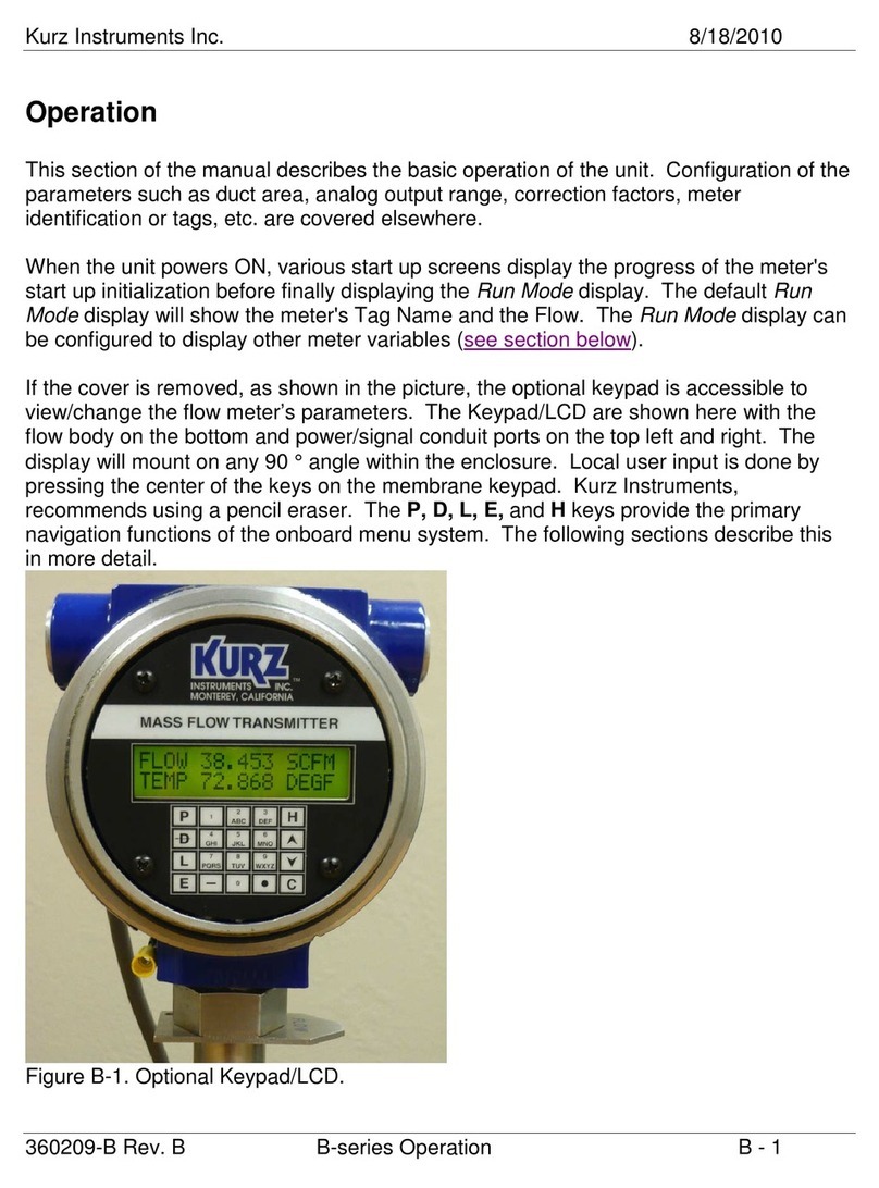
Theflowmeteruserinterface(Figure 1‐1)includesandisplayscreenwithtworowsof16
charactersandakeypadwith20 keys(severalofwhichhavedualfunctions).Youmayneedtouse
asmall‐tippointingdevicetopressthekeys.
Figure 1‐1. Flowmeteruserinterface
Therearesixoperatingmodesforthemeter:
•Boot‐upmode
Occursduringapowercyclewhenthemeterperformsself‐testsfordiagnostics.
•Runmode
AninstalledmeterisnormallyinRunmodetoshowtheflowandtemperatureofthe
processedgas.
•Displaymode
Aview‐onlyofthemeter’sconfigurationparameters.
•Programmode
Allowsyoutomakeconfigurationandparameterchangestothemeter.
•Logmode
Allowsyoutosendreportstothemeter’sserialport.
•ExtendedUtilitiesmode
Allowsaccesstoadvancedmeterfunctions.
ABC DEF
GHI JKL MNO
PQRS TUV WXYZ
123
456
789
P
D
H
0
L
C
E

KurzB‐SeriesOperationsGuide1–3
B‐SeriesFlowMeterModes&Menus
Meter Keypad
Thelargeletterkeysareusedfor:
•ThePkeyaccessesProgrammodeformakingconfigurationchangestothemeter.Thisisa
passwordprotectedmode.
•TheDkeyaccessesDisplaymodeforaview‐onlyofthemeter’sconfigurationparameters.
Itcanalsobeusedasabackspacekey.
•TheLkeyaccessesLogmodeandsendsreportstothemeter’sserialorUSBport.
•TheEkeyaccessesExtendedUtilitiesmodefortheadvancedfeaturesofthemeter.Thisisa
passwordprotectedmode.TheEkeyisalsousedasanEnterkeyandtoacceptandsave
changesafterenteringdata.
•TheHkeyistheHomekeyusedforbackingoutofanymenu.PressHtobackuponelevel
orpressittwicetoreturntoRunmode.
•TheCkeyisusedtoclearadataentryfield.
Thealphanumerickeysincludenumbers0through9,withkeys2through9alsobeingusedfor
lettersAtoZ.Fordatafieldsthatacceptalphabeticdata,continuepressingthealphanumerickey
tocyclethroughtheletters.Forexample,ifyouwantedtoentertheletter“R,”youwouldpress
the7key,pressagainfor“P,”pressagainfor“Q,”andpressagainfor“R.”PresstheEkeytosave
theselectionandmovetothenextfield.
Thesymbolkeysare:
•Theup()anddown()arrowkeysareusedtoscrollthroughamenu.Thescrolloption
isavailablewhenthesymbol^vappears.
•Thebarkey(—)isusedforenteringnegativevalues.
•Thedotkey()isusedforenteringdecimalplaces.
•Thearrowkey()overlayingtheDkeybecomesabackspacekeyafteryouenteramode
andisusedfordeletingcharacterstotheleft.

KurzB‐SeriesOperationsGuide1–4
B‐SeriesFlowMeterModes&Menus
Flow Meter Display Screen
Eachuserconfigurablemodeprovidesmenuoptionsbasedontheaccesscodeyouenter.For
example,onecodemightonlyallowaccesstobasicmetersettingswhileanothercodeallows
accesstoallmetersettings.Fullmeteraccessprovidestheoptionofscrollingthroughthelistof
availablemenuoptionsorenteringthenumberofaspecificmenuitem.
•MenuScrollallowsyoutogothroughallmenuoptionsforthatmode.
•QuickJumpallowsyoutoenteramenunumberwithinthespecifiedmode.
Figure 1‐2. Flowmeterdisplayscreen
Whenmenusuboptionsareavailable,upanddownsymbolsappearattheendofthesecondline.
Figure 1‐3. Menusuboptionindicator
1: M E N U S C R O L L
2: Q U I C K J U M P
^v

KurzB‐SeriesOperationsGuide1–5
B‐SeriesFlowMeterModes&Menus
Boot Mode
Thedeviceboottestverifiesthattheconfiguration,sensor,andwiringarevalid.Thelengthofthe
boot‐uptimevariesonwhetherthesensoriscoldorhotwhenthepowerisapplied.
TheB‐Seriesflowmetercanboot‐upandstartrespondingtoModbuscommunicationsor
updatingthe4‐20mAoutputanddisplaywithinonesecondofrestarting/poweringup.
However, thebootsequencehastocompletetoguaranteetheintegrityofthedata,anditis
generallyrecommendedtowaitanadditional20secondsbeforeissuinganycommands.
Anearzeroflowratecancauseabootdelayupto2minutes,duringwhichtimethevelocity
sensormustcooloffsoitsresistancevaluecanbecheckedtoensuretherearenosensorfaults.
A highprocessvelocityduringboot‐upreducesthedelaybecausethehotsensorcancooldown
faster.
Whenthemeteristurnedonfromapower‐offstate,theNE‐43alarmlow(3.6mAorless)isset
untilthesensorbootprocessstarts.Theflowandtemperaturewillthenincreasetotheirproper
valuesdependingontheprocessvelocitymeterfiltersettings.
Note Firmwareversion1.10andlaterholdtheNE‐43alarmuntilboot‐upand
sensorstabilizationcomplete.
Table 1‐1. NominalBoot‐UpTimes
SettlingTime
(1%Reading,Modbus,4‐20mA,orDisplay)
ColdSensor
(PowerOff)
HotSensor
(PowerCycled)
1600SFPM,velocity,filterTC=0.5seconds 15seconds 17seconds
1600SFPM,temperature,filterTC=0.5seconds 10seconds 13seconds
Zeroflow,velocity,filterTC=0.5seconds 15seconds 60seconds
Zeroflow,temperature,filterTC=0.5seconds 10seconds 55seconds

KurzB‐SeriesOperationsGuide1–6
B‐SeriesFlowMeterModes&Menus
Whenyouboot‐up(poweron)theflowmeter,thedisplayprogressesthroughaseriesof
initializationindicators:
KURZ INSTRUMENTS
DISP DRIVER V4.X
CHECKING TYPE OF
CONNECTED SENSOR
WAIT PERFORMING
SENSOR LEAK TEST
KURZ INSTRUMENTS
SERIES MFT-B
FIRMWARE VERSION
MFT-B VER 2.XX
Note IfthedevicesupportsHartcommunication,anHappearsbeforethe
firmwareversionnumber.
Onceboottestingcompletes,theflowmeterautomaticallygoesintoRunmode.
Anerrormessageindicatestheunithasfailedboot‐uptestingduetoasensormismatch,wiring,
orotherproblem.
•Thedevicewillcyclethroughboottestingagainuntiltheissueisresolved.
Note DownloadingtheMin/Max,Event,andTrendlogsisnotpossibleuntil
boottestingcompletessuccessfully.
•YoucanforceabootexitbypressingtheCkey.
OncebootcompletesyoucanstartdownloadingtheMin/Max,Event,andTrendlogs.

KurzB‐SeriesOperationsGuide1–7
B‐SeriesFlowMeterModes&Menus
Run Mode
RunmodeisthenormaloperationalstateofthemeterafterBoot‐Upmode.Thedefault
informationinRunmodeistheflowmeter’stagnameandflow,asshowninthefollowing
example:
TAG NATURAL GAS1
FLOW 0.0000 SCFM
Firmwareversion2.0andhigherallowyoutodeterminehowprocessvariablesappearinRun
mode.SettingRunmodevariablesisavailablebyselectingoption7inProgrammodewithan
advancedpassword.YoucanalsoaccessRunmodevariablesbyselectingoption1inProgram
modewithabasicpassword,althoughyoumustscrollthroughtheentirebasicsetup.See
“ProgramMode”onpage 1‐11formoreinformation.
Static Variables
Staticshowsonlyonesetofprocessvariables.
•Flowonly
Line1isflow
Line2isblank
FLOW 0.0000 SCFM
•Flowandtotalizedflow
Line1isflow
Line2istotalizedflow
FLOW 0.0000 SCFM
FLTOT 183545.0
•Flowandvelocity
Line1isflow
Line2isvelocity
FLOW 0.0000 SCFM
VEL 0.00000 SFPM
•Tagnameandflow
Line1istagname
Line2isflow
TAG NATURAL GAS1
FLOW 0.0000 SCFM
•Flowandtemperature
Line1isflow
Line2istemperature
FLOW 0.0000 SCFM
TEMP 82.52 DEGF

KurzB‐SeriesOperationsGuide1–8
B‐SeriesFlowMeterModes&Menus
Scrolled Variables
Scrolledshowsallorspecificprocessvariables.Eachprocessvariableprovidesthealabel,avalue,
andtheunitofmeasure.Youalsodeterminefrom2to8secondsthateachprocessvariable
appearsbeforeshowingthenextvariable.
Thescrollcombinationsare:
•Scrollall
•Flowonly
•Flowandtotalizedflow
•Flowandvelocity
•Tagnameandflow
•Tagname,flow,andvelocity
•Flow,totalizedflow,andvelocity
•Flowandtemperature
•Flow,temperature,andvelocity
•Flow
FLOW RATE
0.0000 SCFM
•Temp
TEMPERATURE
82.52 DEGF
•Velocity
VELOCITY
0.00000 SFPM
•Totalizedflow
TOTAL FLOW
183545.0 SCF
•Tagname
TAG NAME
NATURAL GAS1
Other manuals for B-Series
1
Table of contents
Other Kurz Measuring Instrument manuals
Popular Measuring Instrument manuals by other brands

ElektroPhysik
ElektroPhysik MiniTest 7200 FH Technical manual and operating instructions

bluelab
bluelab Truncheon instruction manual

Sierra
Sierra Smart-Trak 100 series Quick installation guide

Ducati Energia
Ducati Energia DUCA-LCD96 Series Assembly and use instructions

Zoom
Zoom F2 Operation manual

PCB Piezotronics
PCB Piezotronics J320C04 Installation and operating manual