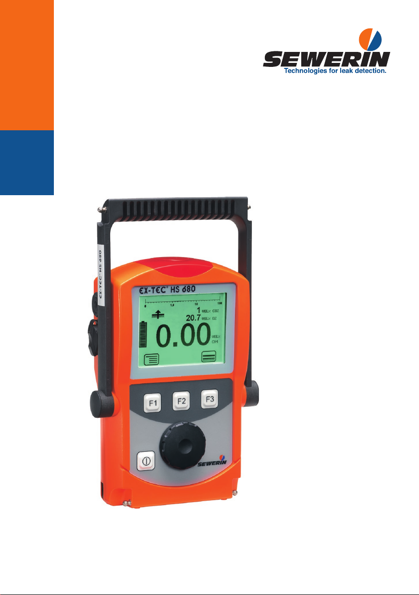
sewerin EX-Tec HS 680 User manual
03.06.2019 a – 105734 – en
EX-TEC®HS 680/660/650/610
Operating Instructions
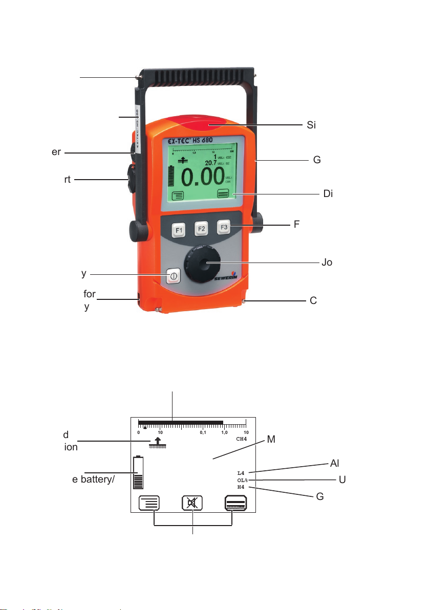
Connector
Buzzer
USB port
ON/OFF key
Connection for
power supply
Signal light
Gas input
Function keys
Jog dial
Connector
Display
CH4
AL4
VOL%
CH4
0,1 1,0
010 100 10
0.90
Measurement value
Capacity
disposable battery/
rechargeable battery
Selected
application
Bar display
Alarm
Unit
Gas type
Current assignment of
function keys F1 – F3
Supporting bracket
Fig. 1: EX-TEC HS 680 device overview
Fig. 2: EX-TEC HS 680 display
EX-TEC®HS 680/660/650/610
General
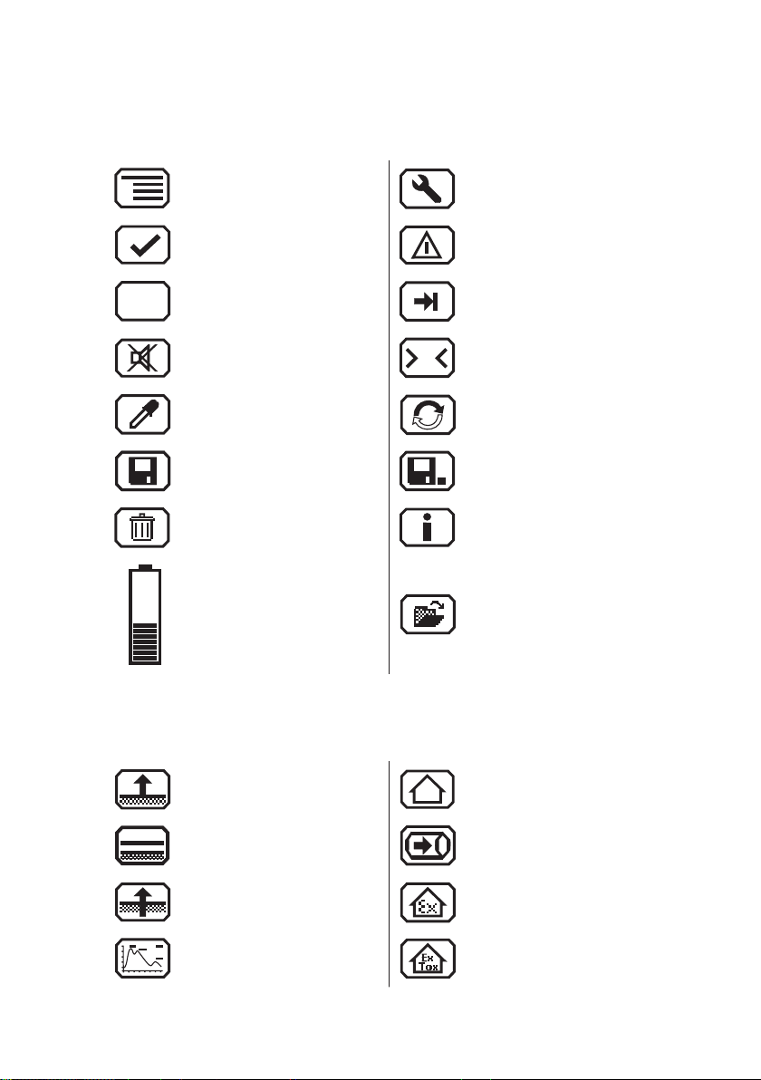
Menu Fault
OK Carry out device inspection
Esc
Cancel Tab (jump to next input
eld)
Buzzer o
0
Set zero point
Take sample Purge
Save Stop measurement
Delete Information
Capacity disposable bat-
tery/rechargeable battery
Open stored comment
Open stored inspector
Applications
Inspection above ground Structure
Plants Gas measuring
Measuring in bar holes Warning %LEL
Ethane analysis Warning ExTox
Display symbols

Information about this document
The warnings and notes in this document mean the following:
ADANGER!
Risk of personal injury. Will result in serious injury or
death.
AWARNING!
Risk of personal injury. Can result in serious injury or
death.
ACAUTION!
Risk of personal injury. Can result in injury or a risk to
health.
Notice!
Risk of damage to property.
Note:
Tips and important information.
Numbered lists (numbers, letters) are used for:
●Instructions that must be followed in a certain order
Lists with bullet points (point, dash) are used for:
●Lists
●Instructions that only involve one step
Numbers between forward slashes /.../ refer to the referenced doc-
uments.

I
Contents Page
1 General.....................................................................................1
1.1 Warranty....................................................................................1
1.2 Purpose.....................................................................................2
1.3 Intended use .............................................................................3
1.4 General safety information ........................................................4
1.5 Allocation of tasks to applications .............................................5
2 Features ...................................................................................6
2.1 Visual and audible signals.........................................................7
2.2 Sensors .....................................................................................8
2.3 Explosion protection..................................................................9
2.3.1 Passive explosion protection..................................................9
2.3.2 Active explosion protection ..................................................10
3 Operation ............................................................................... 11
3.1 General information on operation............................................ 11
3.1.1 Keys and jog dial.................................................................. 11
3.1.2 Selecting/exiting menus and menu items.............................12
3.1.3 Switching the device on .......................................................12
3.1.4 Selecting/changing the application.......................................14
3.1.5 Dierences between measuring mode and settings mode ..15
3.2 Measuring mode .....................................................................15
3.2.1 Accessing the menu (measuring mode menu structure)......16
3.2.2 Zero point .............................................................................17
3.2.3 Inspection above ground......................................................18
3.2.4 Plants ...................................................................................19
3.2.5 Measuring in bar holes.........................................................20
3.2.6 Ethane analysis ...................................................................21
3.2.6.1 General information on ethane analysis............................22
3.2.6.2 Purging the detector..........................................................24
3.2.6.3 Carrying out an ethane analysis........................................25
3.2.6.4 Evaluating an ethane analysis ..........................................26
3.2.7 Structure...............................................................................29
3.2.8 Gas measuring.....................................................................30
3.2.9 Warning %LEL ....................................................................31
3.2.10 Warning ExTox .....................................................................32
3.2.11 Settings ................................................................................33
3.2.12 Start/stop/save a measurement ...........................................33
3.2.13 Protocols ..............................................................................35

II
Contents Page
3.2.14 Device inspection .................................................................36
3.2.15 Gas type CxHy .....................................................................36
3.2.16 Device information ...............................................................37
3.3 Settings ...................................................................................37
3.3.1 Opening settings ..................................................................37
3.3.2 Settings menu structure .......................................................39
3.3.3 Adjustment ...........................................................................40
3.3.4 System .................................................................................42
3.3.5 Alarms ..................................................................................44
3.3.6 Date/time..............................................................................44
3.3.7 Memory ................................................................................44
4 Power supply.........................................................................46
4.1 Suitable disposable/rechargeable battery types .....................46
4.2 Operation with rechargeable batteries ....................................47
4.2.1 Charging...............................................................................48
4.2.2 Rechargeable battery maintenance .....................................49
4.3 Battery alarm...........................................................................49
4.4 Replacing disposable/rechargeable batteries .........................50
5 Maintenance ..........................................................................51
5.1 Device inspection ....................................................................51
5.1.1 General information on the device inspection ......................51
5.1.1.1 Scope................................................................................51
5.1.1.2 Frequency .........................................................................52
5.1.1.3 Documentation..................................................................53
5.1.1.4 Integrated device inspection .............................................53
5.1.1.5 Order.................................................................................54
5.1.1.6 Test gases for the device inspection .................................54
5.1.2 Performing the device inspection .........................................56
5.1.2.1 Accessing the device inspection .......................................56
5.1.2.2 Concluding the device inspection......................................57
5.1.3 Testing the general status ....................................................58
5.1.3.1 Housing.............................................................................58
5.1.3.2 Signals ..............................................................................59
5.1.3.3 Probe.................................................................................59
5.1.3.4 Filter ..................................................................................59
5.1.3.5 Pump.................................................................................59
5.1.4 Testing indication accuracy with supply of fresh air .............60
5.1.5 Testing indication accuracy with supply of test gas..............60

III
Contents Page
5.2 Adjustment ..............................................................................62
5.2.1 Scope ...................................................................................62
5.2.2 Test gases for the adjustment ..............................................63
5.2.3 Special features of adjustment with gas mixture..................64
5.2.4 Preparation...........................................................................65
5.2.5 Performing the adjustment ...................................................65
5.2.5.1 Adjusting the zero point.....................................................66
5.2.5.2 Adjusting the sensitivity.....................................................66
5.2.6 Carrying out an oxygen adjustment .....................................68
5.2.6.1 Adjusting the zero point for oxygen...................................68
5.2.6.2 Adjusting the sensitivity for oxygen...................................69
5.3 Servicing .................................................................................69
6 Faults......................................................................................70
7 Appendix................................................................................71
7.1 Specications and permitted operating conditions..................71
7.2 Alarms .....................................................................................72
7.2.1 Features ...............................................................................72
7.2.2 Occupational exposure limits (OEL) and excess factors
(STEL and LTEL)..................................................................75
7.2.3 Alarm thresholds (factory settings).......................................75
7.2.4 Setting ranges for gas types ................................................76
7.3 Limit values for the device inspection .....................................77
7.4 Memory capacity .....................................................................78
7.5 Sensors ...................................................................................79
7.5.1 Infrared sensors (IR) ............................................................79
7.5.1.1 Methane CH4, propane C3H8, butane C4H10 for
Warning %LEL and Warning ExTox ..................................79
7.5.1.2 Methane CH4, propane C3H8for gas measuring ...............80
7.5.1.3 Carbon dioxide CO2for warning ExTox.............................80
7.5.1.4 Carbon dioxide CO2for measuring in bar holes................81
7.5.2 Electrochemical sensors (EC)..............................................81
7.5.2.1 Oxygen O2........................................................................81
7.5.2.2 Carbon monoxide CO .......................................................82
7.5.2.3 Hydrogen sulphide H2S.....................................................83
7.5.3 Gas-sensitive semiconductor ...............................................83
7.6 Technical information ..............................................................84
7.6.1 Identication sticker (back of device) ...................................84
7.6.2 Cleaning ...............................................................................84

IV
Contents Page
7.6.3 Electrostatic charge..............................................................84
7.7 Accessories and consumables................................................85
7.8 Declaration of conformity ........................................................86
7.9 Inspection protocols ................................................................87
7.9.1 Test with individual gases.....................................................87
7.9.2 Test with gas mixture............................................................89
7.10 Advice on disposal ..................................................................91
7.11 Terminology and abbreviations ...............................................92
7.12 Referenced documents ...........................................................93
8 Index.......................................................................................94

1
1 General
1 General
1.1 Warranty
The following instructions must be complied with in order for any
warranty to be applicable regarding functionality and safe opera-
tion of this equipment. This product must only be commissioned
by qualied professionals who are familiar with the legal require-
ments (Germany: DVGW).
●Read these operating instructions prior to operating the product.
●Use the product only as intended.
●Repairs and maintenance must only be carried out by special-
ist technicians or other suitably trained personnel. Only spare
parts approved by Hermann Sewerin GmbH may be used when
performing repairs.
●Use only suitable battery types, otherwise the device will not
be explosion-proof.
● Changes or modications to this product may only be carried
out with the approval of Hermann Sewerin GmbH.
●Use only Hermann Sewerin GmbH accessories for the product.
Hermann Sewerin GmbH shall not be liable for damages resulting
from the non-observance of this information. The warranty con-
ditions of the General Terms and Conditions (AGB) of Hermann
Sewerin GmbH are not aected by this information.
In addition to the warnings and other information in these Oper-
ating Instructions, always observe the generally applicable safety
and accident prevention regulations.
The manufacturer reserves the right to make technical changes.

2
1 General
1.2 Purpose
The EX-TEC HS 680 and the models 660, 650 and 610 are hand-
held measuring devices which can be used for all gas pipeline
testing applications.
The devices are designed for professional industrial use and
require the necessary specialist knowledge for working in gas
pipelines. Sample applications are described in /3/.
All devices are tted with infrared sensors for measuring hydro-
carbons CXHYand carbon dioxide CO2as standard. Models 680
and 660 also feature a gas-sensitive semiconductor.
Models 680 and 660 can be optionally tted with a detector for
ethane analysis to help you safely distinguish between natural
gas and swamp gas.
All devices can also be individually tted with electrochemical
sensors.
The infrared sensors operate on the principle of absorption via
infrared-active gases, and the electrochemical sensors operate
on the electrochemical cell principle. The gas-sensitive semi-
conductor reacts to changes in conductivity brought about by
reducible gases.
Note:
These operating instructions describe the EX-TEC HS 680 with
all additional equipment (rmware version 2.XXX). All descrip-
tions refer to the device as delivered (factory settings) and apply
to all device versions. The manufacturer reserves the right to
make changes.

3
1 General
1.3 Intended use
This device is intended for professional residential and commer-
cial use including small rms and commercial operations. The
appropriate specialist knowledge is required to operate the device.
The device may only be used to measure the following gases
(depending on the device model and additional equipment):
●Methane CH4/propane C3H8/butane C4H10
●Carbon dioxide CO2
●Oxygen O2
●Hydrogen sulphide H2S
●Carbon monoxide CO
The device must not be used for:
●Gas analysis of technical processes
●Monitoring liquids
The device can be used up to a temperature of 40 ºC. However,
high temperatures reduce the lifetime of the sensors and re-
chargeable batteries.
If a device with an electrochemical sensor is exposed to gas
concentrations above the measuring range limit, this can reduce
the lifetime of the sensor.

4
1 General
1.4 General safety information
●The device has been tested to ensure that it is explosion-proof
in accordance with European standards (CENELEC).
●The device must only be switched on with fresh air.
●Do not use this device in oxygen-enriched atmospheres, oth-
erwise it will not be explosion-proof.
● Only probe hoses with a hydrophobic lter may be used.
Exception:
If the probe has a built-in hydrophobic lter, the hose does not
require any other lters.
●The device must only be tested and adjusted with test gases
in well ventilated rooms or in the open air. Test gases must be
handled in a professional manner.
●Always carry out a device inspection (see section 5.1) after
the device has suered an impact (for example, if dropped
accidentally).
●The device complies with the limits of the EMC directive. Always
observe the information in the manuals of (mobile) radio equip-
ment when using the device close to (mobile) radio equipment.
Note:
Follow the advice regarding explosion protection (see section 2.3).

5
1 General
1.5 Allocation of tasks to applications
The table is designed to help you decide which application to
choose for which activity (in accordance with /3/).
Location Activity Application
Gas lines, gas systems, … ●Measuring the gas concentration
– Purging (to demonstrate purity or absence of gas,
e.g. when commissioning/decommissioning gas systems)
Gas measuring
Buried gas lines ●Measuring very low gas concentrations:
– Ground
– Gas line
– Possible leakage points
Inspection
above ground
●Distinguishing between natural gas and swamp gas Ethane analysis
Gas lines, gas systems, …
in houses, enclosed spaces
and shafts
●Warning against explosive gas concentrations through work
area monitoring
Warning %LEL
●Warning against explosive and toxic gases through work area
monitoring
Warning ExTox
In the ground ●Measuring the gas concentration to:
– Determining gas dispersion (detection limit)
– Classify leaks
– Locating a probable gas escape (repair point)
– Preventing possible dangers
Measuring in
bar holes
Poorly accessible gas pipes,
systems
●Measuring very low gas concentrations
●Locating the source of gas
●Finding leaks
Plants
In the house ●Measuring very low gas concentrations
●Locating the source of gas
●Finding leaks at internal connections
Structure

6
2 Features
2 Features
The device comes in four models:
EX-TEC HS 680
EX-TEC HS 660
EX-TEC HS 650
EX-TEC HS 610
The models are suitable for the following applications:
Application HS 680 HS 660 HS 650 HS 610
Inspection above ground × ×
Measuring in bar holes
O2
×
○
×
○
×
○
×
○
Plants × ×
Structure
CO
×
○
×
○
Gas measuring × × × ×
Warning %LEL × ×
Warning ExTox
CO
H2S
O2
×
○
○
○
×
○
○
○
Ethane analysis ○ ○
× standard ○ optional

7
2 Features
2.1 Visual and audible signals
The device features two alarms:
● Signal light on top of device (visual signal)
● Buzzer on side of device (audible signal)
The signals indicate alarms and faults. The device also emits
signals when it is switched on and o.
If this symbol appears on the display, the audible signal
can be switched o.
When an audible signal has been switched o it cannot
be switched back on while the concentration level re-
mains above the alarm threshold.
This symbol appears at the top left of the display as soon
as the audible signal has been switched o. It disappears
automatically if the level falls below the alarm threshold.
Operating signal
When using the Warning %LEL and Warning ExTox applications,
the device emits a visual and audible signal at regular intervals.
This indicates that the device is working properly.
Alarm
The device can monitor several gases at the same time. If the
measured gas concentration of one or more gases exceeds spec-
ied limit values (alarm thresholds) the device gives a warning. It
emits both audible and visual signals, which are clearly dierent
from the operating signal.
AWARNING! Risk to life from dangerous gas concen-
trations
An alarm always indicates danger.
●Take all necessary measures for your own safety and
the safety of others immediately.
There is detailed information on alarms in section 7.2.

8
2 Features
2.2 Sensors
The device features three types of sensor:
● Gas-sensitive semiconductor (SC)
● Infrared sensor (IR)
● Electrochemical sensor (EC)
Application Gas Measuring range Sensors
Inspection above
ground
CH41 ppm – 10 % vol. SC, IR
Plants CH41 ppm – 100 % vol. SC, IR
Measuring in bar
holes
CH40.0 – 100 % vol. IR
CO20 – 30 % vol. IR
O20 – 25 % vol. EC
Ethane analysis CH4--- Gas chroma-
tograph, SC
C2H6
C3H8
Structure CH41 ppm – 100 % vol. SC, IR
CO 0 – 500 ppm EC
Gas measuring CH40.0 – 100 % vol. IR
Warning %LEL and
warning ExTox
CH40 – 100% LEL IR
CO 0 – 500 ppm EC
CO20 – 5 % vol. IR
O20 – 25 % vol. EC
H2S 0 – 100 ppm EC

9
2 Features
2.3 Explosion protection
2.3.1 Passive explosion protection
The device is assigned to the following explosion-proof groups:
Explosion-proof
group
For the following
atmospheres
When
using
II2G Ex d e ib IIB T4 Gb – Methane CH4
– Propane C3H8
– Butane C4H10
– Hydrogen sulphide H2S
– Carbon monoxide CO
Device
without
carrying
bag TG8
II2G Ex d e ib IIC T4 Gb – Methane CH4
– Propane C3H8
– Butane C4H10
– Hydrogen sulphide H2S
– Carbon monoxide CO
– Hydrogen H2
Device
with
carrying
bag TG8
EC type-examination certicate: TÜV 07 ATEX 553353 X
ADANGER! Risk of explosion from sparks
●Only ever open the battery compartment outside of
explosive areas.
●Only ever charge the device outside of explosive areas.
●Only use the USB port outside of explosive areas.
●Use only suitable battery types.
●When working with hydrogen, always use the TG8 car-
rying bag for the device.

10
2 Features
2.3.2 Active explosion protection
The functional safety test applies to:
Applications: Warning %LEL
Warning ExTox
Gas types: Measuring range:
– Methane CH40 – 100% LEL
– Propane C3H80 – 100% LEL
Gases: Measuring range: As per:
– Oxygen O20 – 25 % O2/7/
– Carbon dioxide CO20 – 5 % CO2/5/
– Carbon monoxide CO 0 – 500 ppm CO /5/
– Hydrogen sulphide H2S 0 – 100 ppm /5/
Tested accessories: – Test set SPE VOL
– Flexible hand probe, 1 m
– Floating probe 2 m / 6 m
Type examination
Testing institute: DEKRA EXAM GmbH
Certicates: PFG 08 G 002 X
BVS 09 ATEX G 001 X
The following points were not part of the type examination:
●Saving measurement data (see section 3.2.12)
●Saving protocols from the integrated device inspection (see
section 5.1.1.4)
●Disposable alkaline batteries for the power supply (see sec-
tion 4.1)

11
3 Operation
3 Operation
3.1 General information on operation
3.1.1 Keys and jog dial
The ON/OFF key is the only control on the device that does not
change its function.
When switched on, the device is operated using the jog dial and
function keys to navigate the display.
Control Action Function
ON/OFF key Press ●Switches the device on
● Switches the device o
Function keys
F1, F2, F3
Press ●Variable
●As indicated on the display at
the bottom of the screen
●Function keys may also have
no function assigned in some
cases
Jog dial Turn ●Selects functions, settings,
measurement data, etc.
● Modies values
Press ●Opens the next program lev-
el (for example, menu item,
function, measurement data,
selectable values)
●Accepts values

12
3 Operation
3.1.2 Selecting/exiting menus and menu items
Functions, applications and settings etc. are selected via the
main menu (for short: Menu). This menu has submenus and
menu items. Refer to section 3.2.1 for information on accessing
the menu.
Selecting submenus/menu items
Submenus and menu items are selected and opened using the
jog dial and/or the function keys.
In measuring mode the name of the selected application is in-
dicated by the symbol at the top left of the display. You can nd
detailed information on selecting and switching applications in
section 3.1.4.
Exiting menus/menu items
There are generally two ways to exit open menus/menu items
and return to the next level up:
●Press Esc
●Select Back from the menu
3.1.3 Switching the device on
Note:
Always switch the device on with fresh air.
1. Press the ON/OFF key. The device switches on.
The switching on process involves an internal check.
Process Test purpose
Buzzer emits audible
signal.
Is the audible signal working?
Signal light gives visual
signal.
Is the visual signal working?
Display is inverted. Are there pixels missing from the
display?
This manual suits for next models
3
Table of contents
Other sewerin Measuring Instrument manuals

sewerin
sewerin SR2-EX-P User manual

sewerin
sewerin Multitec 560 User manual

sewerin
sewerin Multitec 540 User manual

sewerin
sewerin COMBIPHON User manual

sewerin
sewerin SPE 2 User manual

sewerin
sewerin FLIS-EX User manual

sewerin
sewerin EX-TEC PM 4 User manual

sewerin
sewerin VARIOTEC 480 EX User manual

sewerin
sewerin Multitec 545 User manual

sewerin
sewerin Stethophon 04 User manual


