manuals.online logo
Brands
  1. Home
  2. •
  3. Brands
  4. •
  5. Kurzweil
  6. •
  7. Synthesizer
  8. •
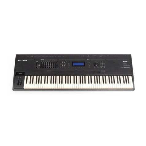
  9. Kurzweil K250 User manual

Kurzweil K250 User manual

·----.......-
.
,.,
...
Kurzweil250
SERVICE MANUAL
(K250, K250X
and
RMX
Models)
Kurzweil Music Systems, Inc.
411
Waverley Oaks Road
Waltham, MA 02154
(617) 893-5900
January, 1989
Document No.: 92000201
~-
-
~--
./
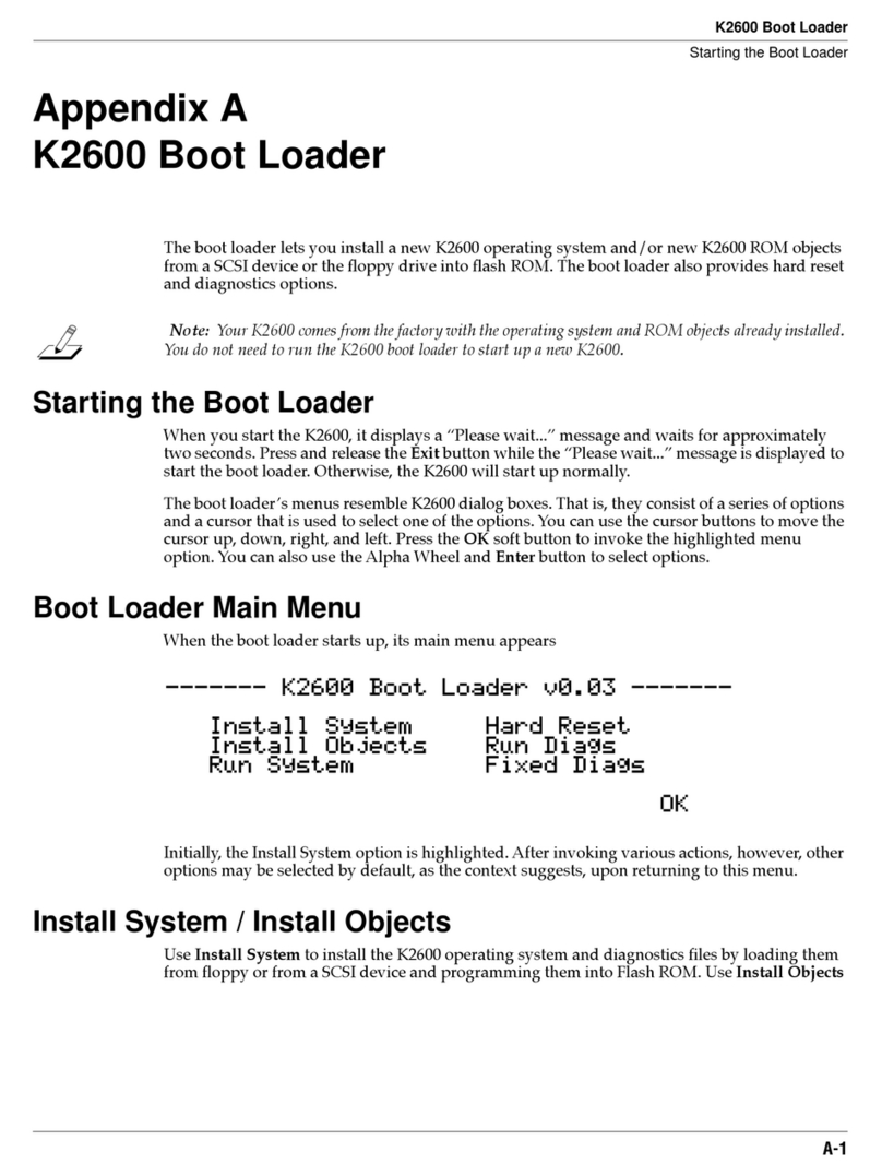
CHAPTER
1
CHAPTER
2
CHAPTER
3
CHAPTER
4
CHAPTERS
CHAPTER
6
CHAPTER
7
Table of Contents
INTRODUCTION
PRODUCT
HISTORY
SYSTEM
OVERVIEW
DIAGNOSTICS
DISASSEMBL
Y/ASSEMBL
Y
PROCEDURES
PARTS
LISTS
SCHEMATICS,
LAYOUTS,
WIRING
DIAGRAMS
KURZWEIL
MUSIC
SYSTEMS,
INC.
411
WAVERLY
OAKS
ROAD
WALTHAM,
MA
021S4
DOCUMENT
PART
NO.
92000201
January,
1989
Kurzweil Music Systems,
Inc.
The information contained herein
is
confidential and proprietary
to
Kurzweil Music
Systems, Inc. It
is
disclosed
to
you
solely for purposes of instruction
as
to
operation of
the
equipment
and
maintenpnce
as
appropriate. It
is
not
to
be
used
by
you
for any other
purpose, nor is it to
be
disclosed
to
others without the express permission of Kurzweil
Music Systems, Inc.
Kurzwell 250 Service Manual
i
•..
_---
----
.~
Chapter 1 - Introduction
1.1
Product Description
1.2 Specifications
1
.2.1
Kurzweil 250
1.2.2 Kurzweil 250X
1.2.3 KurzweiI 250 RMX
and
225 RMX
1.3 How the Kurzweil 250 Works
1.3.1
Masters Section
1.3.2 Assignments Section
1.3.3 Selection Section
1.3.4 Program Section
1.3.5 Media Section
1.3.6 Back Panel
Kurzweil 250 Service Manual, Chapter 1
1 - 1
1-2
1-3
1-3
1-3
1-4
1-5
1-5
1-5
1-6
1-6
1-7
1-7
1.1 -PRODUCT DESCRIPTION
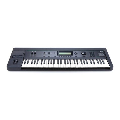
The Kurzweil 250 uses artificial intelligence principles and a
Motorola
68000
microprocessor
to
create
complex
models of
acoustic sounds. The Kurzweil 250's design gives the instrument a
velocity-sensitive keyboard so that a
note's
volume·
and timbre
relates to the force
on
the key. The 12-note, polyphonic keyboard
can accurately reproduce the sounds of several instruments
at
once
and each key
on
the 88 note keyboard can be individually assigned
to
play a different sound.
Currently,
the
Kurzweil
250
comes
with
36
different
instruments arranged into 98 keyboard setups in the basic Enhanced
Resident Sound Block excluding Sound Blocks A thorugh
D.
The
original Kurzweil 250 came with 30 different instruments arranged
into
40
keyboard setups.
The Kurzweil
250's
sequencer
is a
built-in,
12,OOO-note
multi-track digital recorder, which can be used to build up to 12
different tracks. Older Kurzweil 250's may have either 4,000 or
8,000 note sequencer. These units can be updated
to
the current
12,000 with the purchase of available options.
All
Kurzweil
250s
are
currently
manufactured
with the
Kurzweil Sound Modeling Program for user sampling. Older Kurzweil
250s may not have this option, but may be updated with the purchase
of the Sound Modeling Program option.
There are many configurations
of
Kurzweil 250s currently
in
the field. The Kurzweil 250 Product Line also includes the Kurzweil
250X,
an
expander unit without keyboard, and the Kurzweil RMX 250
or 225, a rack mount expander unit. Please see the Product History,
Chapter 2, for more information.
Kurzwell
250
Service Manual, Chapter 1
1 - 2
1.2 -SPECIFICATIONS
1.2.1 -
Kurzweil
250
Keyboard:
88 keys with velocity-sensing and piano action.
Pedals:
2,
assignable piano-type
in
the POD,
2,
external
volume-type
Dimensions
(Cabinet):
56"(L) X 27"(W) X 9"(H)
Dimensions
(POD): 22"(L) X
11
"(W) X 4.5"(H)
Weight
(Cabinet):
95 Ibs.
Weight
(POD): 22 Ibs.
Power
Consumption:
110/220 VAC, 50/60Hz, 380 watts
max.
Operating
Conditions:
0
to
50
0C Ambient 20 to
80%
Relative Humidity
Storage
Conditions:
-25
to
1250C,10 to 90% Relative
Humidity
Audio
Outputs:
High level, Low level, Balanced, Stereo
headphones
External
I/O: High-speed parallel computer port, MIDI In,
MIDI Out and MIDI Thru ports, Sync In, Sync Out, Trigger In,
Click Out, MIC, Line In, 2 External volume-type pedals,
cartridge slot
1.2.2 -
Kurzweil
250X
Dimensions
(Cabinet):
49
1/2"
(L)
X
20
1/2"
(W)
X 6
3/4"(H)
Dimensions
(POD): 22"(L) X 11"(W) X 4.5"(H)
Weight
(Cabinet):
45 Ibs.
Weight
(POD): 22
Ibs.
Power
Consumption:
110/220 VAC, 50/60Hz, 380 watts
max.
Operating
Conditions:
0
to
50
0C Ambient
20
to
80%
Relative Humidity
Storage
Conditions:
-25 to 1250C,10 to
900/0
Relative
Humidity
Audio
Outputs:
High level, Low level, Balanced, Stereo
headphones 1
External
I/O: High-speed parallel computer port, MIDI In,
MIDI Out and MIDI Thru ports, Sync In, Sync Out, Trigger In,
Click Out, MIC, Line
In,
2 External volume-type pedals
Kurzwell
250
ServiceManual, Chapter 1
1 - 3
1.2.3 -
Kurzweil
250 RMX AND 225 RMX
Dimensions
(Cabinet):
19"
(L)
X 22" (W) X 10 1/2"(H)
Weight
(Cabinet):
53 Ibs. r
Power
Consumption:
110/220 VAC, 50/60Hz, 380 watts
max.
Operating
Conditions:
0
to
50
0C Ambient 20 to
800/0
Relative Humidity
Storage
Conditions:
-25 to 1250
C,1
0 to
90%
Relative
Humidity
Audio
Outputs:
High level, Low level, Balanced, Stereo
headphones
External
I/O: High-speed parallel computer port, MIDI In,
MIDI Out and MIDI Thru ports, Sync
In,
Sync Out, Trigger In,
Click Out, MIC, Line
In,
2 External volume-type pedals
Kurzwell
250
ServiceManual, Chapter 1
1 • 4
1.3 -HOW THE KURZWEIL 250 WORKS
This section describes briefly how the Kurzweil 250 controls
work. Refer to the Kurzweil 250 rUser's Guide for more detailed
information. Since this is a complex instrument, always confirm
that
a problem
truly
exists before
attempting
to·
service the
instrument.
1.3.1 -
Masters
Section
The group of slider controls
in
the Masters section controls the
overall sounds that the instrument makes.
TUN
E - Use this slider control to control the overall pitch of
all active voices.
INSTRUMENT GROUPS A & B - These two sliders move two
different, assignable instrument groups from left to right in
the stereo image.
VOlUM
E - This controls overall volume.
1.3.2
-
Assignments
Section
This section
of
the Front Panel controls are used primarily
during live performance.
Each of the three vertical sliders can
be
assigned to control one
of approximately
20
different functions such as tremolo, pitch bend,
vibrato, legato, attack, decay and sustain. By using these controls,
you can simulate a wide variety of playing techniques, including a
full variety of synthetic effects.
Musicians can also assign the foot pedals and Mod
levers
using
switches
in
this section.
Kurzwell
250
Service Manual, Chapter 1
1 - 5
1.3.3 -
Selection
Section
The Selection area
on
the Front Panel contains the switches
that allow users to control the main r functions of the system. With
the LCD display, they tell what operating mode' the instrument is
in
and allow the musician to make changes and answer questions.
SPLIT KEYBOARD -This is another control used at per-
formance time. It allows you
to
assign a certain section of
the keyboard temporarily to a certain instrument.
CHORUS
-When you press this button, you can turn one sound
into many. The "Chorus" capability can be used for doubling,
built-in echo and flanging.
SELECTION SWITCHES -The YES,
NO
and SELECT switches are
used to choose options and answer questions displayed
on
the
LCD.
NUMERIC KEYPAD -Use the numeric keypad to enter choices
and
to
select functions (with the "F" switch).
1.3.4 -
Program
Section
This group of controls, along with the numeric keypad, allow
you to program the Kurzweil 250. These controls are generally used
for setup before a performance.
CURSOR KEYS -The cross shaped group of keys below PLAY are
the cursor controls. The center key (R) is for resetting when
you have made a mistake or want to return to the initial cursor
placement.
S
EQU
ENCER - The Kurzweil 250's sequencer is a built-in,
12,000 -note multi-track digital recorder. You can use it to lay
down one instrument and then play a second instrument on top
of it.
By
repeating this process, you can build up to 12 diff-
erent tracks.
Other keys
in
this section speed up or slow down the tempo of a
piece, modulate
to
another key, change modes or edit keyboards,
instruments or sequences.
Kurzwell
250
ServiceManual, Chapter 1
. 1 - 6
t"--
1.3.5 -
Media
Section
The Media section lets
you
program, store and recall your
own
set of keyboard setups, instruments and .sequences.
LIST
-This key allows you to
run
through,
in
any order, every
keyboard setup stored
in
the Kurzweil 250's memory. You can
reprogram this list to meet you own performance needs. You
can also list sequences using this switch.
STORAGE - The Storage
READ
switch is used to prepare the
instrument to use a cartridge.
In
future versions of the in-
strument, the STORAGE switches will be used with external
media options.
1.3.6 -
Back
Panel
The back panel contains all the input/output connections for the
Kurzweil 250.
COMPUTER
-This
is
the parallel computer port for attaching a
personal computer
to
the Kurzweil 250.
TRIGGER
IN
-The Trigger
In
is
a TTL-compatible input used for
starting a sequence from
an
external device. The sequence
triggers
on
the positive edge of the supplied pulse. Minimum
pulse width
is
1 microsecond. The input impedance is greater
than 10k ohms. The trigger level
is
2 volts. This I/O port takes
a 1/4 inch phone jack.
CLICK OUT -The Click Out is a TTL-level output pulse. When
enabled from the Front Panel, a positive pulse appears at this
output. Its repetition rate
is
the selected sequencer tempo.
Driving source
is
a low power TTL gate through a
51
ohm resis-
tor. This I/O port takes a 1/4 inch phone jack.
SYNC
IN
-The Sync
In
is
a TTL-compatible input used
to
drive
the Kurzweil 250 from another instrument. The other instru-
ment
is
to provIde a square wave at X12
to
X96 the tempo. The
input impedance
is
greater than 10K ohms. The trigger level
is
2 volts and this I/O port takes a 1/4 inch phone jack.
Kurzwell 250 Service Manual, Chapter 1
1 - 7
SYNC OUT -The Sync Out is a TTL-level square wave. output
used to drive other instruments
in
synchrony with the Kurzweil
250. The repetition rate is normally X12 to X96 the tempo. The
driving source is a low powerr TTL gate through a
51
ohm
resistor. This I/O port takes a 1/4 inch phone jack.
MIDI
IN
-This is a 31.2K baud, 5 milliamp serial input.
MIDI THRU -This is a 31.2K baud, 5 milliamp serial output.
MIDI OUT -This is a 31.2K baud, 5 milliamp serial output, the
same
as
MIDI
IN
buffered.
LO
-These are 2 VPP audio outputs, with a 600 ohm driving
source impedance. These require 1/4 inch phone jacks and are
suitable for line level inputs.
ill
-These are 20 VPP audio outputs, with a 600 ohm driving
source impedance. These require 1/4 inch phone jacks and are
suitable for directly driving power amplifiers and other high
level
inputs.
BALANCED
-These are
20
VPP audio outputs. They have XLR
connectors, floating outputs and a 600 ohm driving source
impedance.
EXTERNAL PEDALS 1 & 2 - The 1/4 inch phone jacks accept
assignable pedal functions (K250 and K250X only).
M.lQ.
-This digitizer input is a 200 mVPP full scale input. It
has a 47K ohm input impedance and accepts a 1/4 inch phone
jack.
LINE
IN
-This digitizer input is a 1 VPP full scale input (300
MV
rms.) It has a 10K ohm input impedance and accepts a 1/4
inch phone jack.
Kurzweil
250
Service Manual, Chapter 1
1 - 8
Chapter 2 - Product History
2.1
2.2
2.3
2.4
2.5
2.6
2.7
2.8
2.9
2.10
2.11
2.12
2.13
2.14
2.15
2.16
History Introduction
February, 1985
Version 2 Software
RAM Sequencer Expansion
Sound Modeling Program (25kHz)
May, 1985
Sound Block A
June, 1985
New K250 Configurations
August, 1985
Kurzweil 250X Introduced
October, 1985
Version 2.2 Software
50kHz Sound Modeling Program
50kHz Sound Modeling Program Upgrade Kit
March,1986
Version
3.1
Software
Enhanced Resident Sound Block (CGP)
Sound Block B
August, 1986
Version 3.2 Software
QLS
Sound Block C
December, 1986
Version 4 Software
Superam I and
1/
Sound Block D
March,1987
RMX Introduced
April,1987
Version
4.1
October, 1987
Version 5 Software
Separate Outputs
September, 1988
Version 6 Software
RAM Cartridge
RAM Cartridge Adapter
Software Version Versus Options Available
2.14.1 Version 2
2.14.2 Version 2.2
2.14.3 Version
3.1
2.14.4 Version 3.2
2.14.5 Version 4 and
4.1
2.14.6 Version 5
2.14.7 Version 6
Sound Block Positioning for Enhanced Resident Sound Block
Options Versus K250 Configuration
1
Kurzweil
250
Service Manual, Chapter 2
2-1
2-2
2-3
2-4
2-5
2-5
2-6
2-7
2-8
2-10
2-11
2-11
2-12
2-12
2-14
2-14
2-14
2-14
2-15
2-16
2-17
2-18
2-20
2-22
2.1
-History Introduction
The following outlines possible configurations of K250s in the
field. When the K250 was first introduced to the field
in
August of
1984 the K250 contained Version 1 so'tware and no options. Please
be aware that some options are required and some are optional.
Please refer to the "Software Versions Versus Options Available"
list included
in
this chapter for configuration information.
Note: Specific part numbers are mentioned
in
this document
pertaining to parts included
in
option kits. However, not all part
numbers required for certain options are mentioned. This document
has been prepared to give you a brief history of the options and
updates for the K250, K250X and the
RMX
250 and 225. This chapter
is not meant to replace the installation procedure supplied with
each option kit.
The Kurzweil 250, K250X and RMX contain the following
printed circuit boards:
CPU/Central Processing Unit
CGP/Channel Group Processor
Channel
Audio
Slider
LCD
Control Panel
Bass and Treble Keyswitch boards (K250 only)
Power Supply (internal,
RMX
models only)
Kurzwell
250
Service
Manual,
Chapter
2
2 - 2
2.2 -
February,
1985
Version
2'
software
update--a
no
'charge update
Ram
Sequencer
Expansion--purchased
option bringing the
Sequencer from 4K to
8K
Sound
Modeling
Program
(25kHz)--purchased option*
*Sound Modeling Program also referred to as sampling
The
Version
2 free software update was offered to all K250
owners and required some modification to the
C.PU
board and the
replacement of the 8 software EPROMs located. at:
82051001
82051201
82051401
82051601
U54
U53
U52
U51
82051101
82051301
82051501
82051701
U38
U37
U36
U35
The RAM
Sequencer
Expansion
required the installation of
four memory chips part
no.
62000901
in
locations U28, U29, U43 and
U44. The original Ram Sequencer Expansion kit included a
replacement for U95 on the CGP board, however, this part is not
included
in
the current kit.
The
Sound
Modeling
Program
required a unit with Version 2
software and involved the update of three p.c. boards, the CPU, CGP,
Channel; and the possible replacement of the Audio board.
The CPU board with Version 2 installed only required that
you install part no. 82000408
in
U25, part no. 82000409
in
U40, part
no.
82000410
in
U26 and part no. 82000411
in
U41.
The
CG
P board required 3 cuts to the solder side of the
board and 3 jumps
to
the component side of the board. It also
required the installation of
20
DRAM chips
in
locations U25
through U29, U33 through U37,
U51
through U55 and U72
through U76. The
CGP
board while installed
in
the K250. These
locations are
~asily
found by looking at the inner right hand
corner of the CGP board.
Kurzweil
250
Service Manual, Chapter 2
2 - 3
The Channel board required the installation of U60, part" no.
63001201. Some units did not.have a socket at this location;
and, therefore, required the addition of that socket. This
socket was supplied with the kit. Kurzweil never recommends
that this part is soldered into the board. It was also required
to check values of certain resistors
and
capacitors on the
Channel board and the addi-tion or replacement of these parts.
The Audio board needed
to
be
replaced for any unit produced
prior to February of 1985. Therefore, Kurzweil offers two
Sound Modeling Program kits, one with Audio board and one
without. (Kurzweil offers these kits at the same cost.) The
part number of the Audio board required for Sound Modeling
Program is 12011001. Some boards may not actually have this
part number printed
on
it, but will have the correct p.c. board
fabrication number, 33011001. The old Audio board that needs
to
be
removed is part no. 12001001 or
p.
c.
board fabrication
no. 33001001.
2.3 -May, 1985
Sound
Block
A--purchased option
The
Sound
Block
A board was offered under three part
numbers 14000801, 14000802 or14001301. Although there was
no
difference
in
the Sound Block A board itself, this was done as a
result of the K250s
in
the field. Older K250s did not have a series
of modifications to the CGP board required for Sound Block
A.
For
these units, Kurzweil offered kit part number 14000801. This
included
an
updated CGP board
as
well as the Sound Block A board.
The old CGP was to be returned to Kurzweil or the customer was
invoiced for the board. Part number 14000802 was used for
customers who sent
in
their CGP board to be updated at Kurzweil.
Once the update was completed Kurzweil returned the CGP board
with a Sound Block A board attached. This update
to
the
CGP
board
was done free of charge. Part number 14001301 was just the Sound
Block A board sent
to
be installed
on
CGP
boards that did not require
any modification.
Kurzweil
250
Service Manual, Chapter 2
2 - 4
.r
The Sound Block A board
is
mounted
on
the CGP board.
If
you
look at a CGP board installed
in
the K250, you will notice a long
white connector' (47A) mounted
on
the board
in
the lower left hand
quarter of the board. The Sound Block A board is plugged into this
connector and mounting hardware is rinstalled to secure it.
How
to
know if the
CGP
board is ready for the addition of the
Sound
Block'
A board? Check
in
the vicinity
of
the long white
connecter (47A) located
in
the lower left· hand quarter
of
the CGP
board. If this board has been modified to accept a Sound Block A
board, you will notice some rework wiring coming from U126, U134
and U149,
to
name a few. This wiring will begin at these locations
and encircle the white connector and end at locations below.
2.4 -June, 1985--new Kurzweil 250 configurations
Part
No.
10001601--Basic
unit,
no
sampling or sound
block
Part
No. 10001701--Full
unit,
w/Sound Block A
Part
No.
10001801--Advanced
Sampling,
w/Sampling and
Sound Block A
Note:
These units contained
the
Ram
Sequencer
Expansion
option as standard.
2.5 -
August,
1985--Kurzweil 250X introduced
Part
No.
10001901--Basic
unit,
no
sampling or sound
block
Part No. 10002001--Full
unit,
w/Sound Block A
Part
No. 100021
01--Advanced
Sampling,
w/Sampling and
Sound Block A
Note:
These units also contained the Ram
Sequencer
Expansion
option
as
standard.
Kurzwell 250 ServIceManual, Chapter 2
2-
5
At
introduction,
the
Kurzweil
250X
was
introduced
'with
Version
2.1
software. This software. did
not
support sampling and
sampling could not be used with the K250X until Version 2.2, which
will be discussed later. .An important difference between the K250
and the K250X is that every K250X produced had its program EPROMs
contained
in
256K EPROMs. The Kurzweil 250 used 128K EPROMs at
that time.
2.6 -
October,
1985
Version
2.2
introduced--free
update
50kHz
Sound
Modeling
Program--purchased
option
50kHz
Sound
Modeling
Upgrade
Kit--purchased
upgrade
Version 2 software was now obsolete.
Version
2.2
supported
50kHz sampling and corrected some known bugs
in
Version
2.
It
was
a free update,
but
was only offered to
customers
who were
experiencing problems or who were purchasing a Sound Modeling
Program or a 50kHz Upgrade Kit. One thing to note is that if a
customer had a unit with 25kHz sampling and wanted Version 2.2,
the unit had to be upgraded to 50kHz. The Version 2.2 EPROMs should
be the following:
82051021
82051221
82051421
82051621
U54
U53
U52
U51
82051121
82051321
82051521
82051721
U38
U37
U36
U35
The
50kHz
Sound
Modeling
Program
was offered
in
the
same way the 25kHz options were offered. Kurzweil continued to
offer two kits (with
or
without Audio board)
for
purchase. The
modifications to the K250 were basically the same as those outlined
in
the installation procedures for the 25kHz upgrade. However, not
all modifications were necessary for units recently produced.
Kurzweil 250 Service Manual, Chapter 2
2 - 6
The 50kHz
Sound
Modeling
Upgrade
Kit
requireo that the
K250 had Version 2.2 installed. The. sampling EPROMs
on
the CPU
board needed to· be replaced with part no: 82000412 at U25, part no.
82000413 at U40, part no. 82000414 at U26; and part no. 82000415
at U41. The
AID
converter at U60 Ion the Channel board must be
replaced with part no. 63001701 and one cut and one jump is
required.
Note:
When installing the 50kHz Sound Modeling Program or
the 50kHz Upgrade kit, the cut and jump to the Channel board
is
not
necessary
on
the K250X. Every K250X produced had this modification
already performed. Also, modifications to the CGP board required
for Sound Block A and sampling are not required.
2.7
-
March,
1986
Version
3.1
software--pu
rchased option
Enhanced
Resident
Sound
Block--purchased
option (new
CGP)
Sound
Block
8 (Rock Block)
The installation of
Version
3.1
in
K250s required cuts and
jumps
to
the CPU board. These modifications were required
to
add
the additional 4K memory and to reconfigure the board for the
installation
of
256K EPROM (CPU until this point used 128K EPROMs).
Version
3.1
also required units with 25kHz sampling to be
upgraded
to
50kHZ sampling. Because Version
3.1
supported a 12K
sequencer memory, units with only 4K had to be upgraded to 8K. The
installation of Version
3.1
involves installing the Version
3.1
EPROMs at the following locations:
82101401
82101601
82101801
82090401*
U54
U53
U52
U51
82101501
82101701
82101901
82090501*
*50kHz Sound Modeling EPROM locations
,-
Kurzweil
250
Service Manual, Chapter 2
2 - 7
U38
U37
U36
U35
Note:
The Kurzweil 250X
CPU
board does not
requir~
any cut
or jump. It is only necessary to remove the Version
2.1
or 2.2
EPROMs and install the Version 3 EPROMs.·
The installation of the
Enhanoed
Resident
Sound
Block
requires Version 3.1. For units with Sound Block A boards, the Sound
Block A board could be reinstalled
on
the Enhanced Resident Sound
Block. Or, if the Sound Block A chips were socketed; they could
be
removed and installed on the Enhanced Resident Sound Block
in
the
empty sockets designated for the sound block.
When installing the Enhanced Resident Sound Block, be sure
to
remove the 20 DRAMs, if present, located on the old CGP and
reinstall them
on
the Enhanced Resident Sound Block. Failure to
do
so
will render sampling useless.
Sound
Block
B may be installed
on
a Sound Block A board or
the Enhanced Resident Sound Block. If Sound Block B is being
installed
on
a Sound Block A board be sure that there are sockets for
the chips. These sockets are supplied with the kit
if
ordered
properly. Kurzweil does not recommend
that
these chips are
soldered into the Sound Block A board. Therefore, when ordering a
Sound Block
B,
please specify if it will be installed
in
a Sound Block
A board. If Sound Block B is being installed
in
a Enhanced Resident
Sound Block it is only necessary to plug the chips
in
the sockets
specified.
Note: When updating units to Version
3.1
without sampling. be
sure to remove the old Version 2 or 2.2 EPROMs at locations U35 and
~
2.8 -
August,
1986
Version
3.2 software--purchased option
QLS--purchased option
Sound
Block
C (Classical Block)--purchased option
Kurzweil 250 Service Manual, Chapter 2
2 - 8
To
install
Version
3.2
in
units that currently have Version
3.1, no modifications will be required to the CPU board. Simply
remove the Version
3.1
EPROMs and install Version
3.2~
To install
Version 3.2
in
units with software levels earlier than Version 3.1,
the CPU board will require modification as mentioned
in
the
description of Version 3.1. The Version
3.2·
EPROMs should be
installed
in
the following locations:
82102001
82102201
82102401
82090701*
U54,
U53
U52
U51
82102101
82102301
82102501
82090801*
*50kHz Sound Modeling EPROM locations
U38
U37
U36
U35
Version 3.2 is required to install
QLS.QLS
contains a p.c.
board, Macintosh disk and cable. The installation of the QLS
p.C.
board requires removing the parallel port chip
in
location U108
on
the
CPU
board. The QLS p.c. board
is
plugged into the empty socket at
U108 and supported with mounting hardware. It
is
a fairly simple
installation, however, the pins
on
the solder side of the QLS p.c.
board may break off if bent.
Sound
Block
C may
be
installed
on
a Sound Block A board or
the Enhanced Resident Sound Block. Note: if the unit currently has a
Sound Block A board with Sound Block B installed it
is
not possible
to
add Sound Block
C.
If Sound Block C
is
being installed
on
a Sound
Block A board be sure that there are sockets for the chips. These
sockets are supplied with the kit if ordered properly. Kurzweil does
not recommend that these chips are soldered into the Sound Block A
board. Therefore, when ordering a Sound Block
C,
please specify if it
will be installed
in
a Sound Block A board. If Sound Block C
is
being
installed
in
a Enhanced Resident Sound Block, it is only necessary to
plug the chips
in
the sockets specified.
Note:
QLS may not be installed
in
units that do not have
sampling.
Note: When updating units to Version 3.2 without sampling. be
sure
to
remove the
o~d
Version 2 or 2.2 EPROMs at locations U35 and
U51.
Kurzwell
250
Service Manual, Chapter 2
2 - 9
2.9 -
December,
1986
Version
4'
software--purchased
option
Superam
I
or
Superam
II--purchased
option*
*requires Enhanced Resident Sound Block
Sound
Block
D (Brass Block)--purchased option
To install
Version
4
in
units that currently have Version
3.1
or 3.2,
no
modifications will be required to the CPU board. Simply
remove the Version
3.1
or 3.2 EPROMs and install Version 4. To
install Version 4 in units with software levels earlier than Version
3.1
or 3.2, the CPU board will require modification as mentioned
in
the description of Version 3.1. The Version 4 EPROMs should be
installed
in
the
following locations:
82102601
82102801
82103001
82091001*
U54
U53
U52
U51
82102701
82102901
82103101
82091101*
*50kHz Sound Modeling EPROM locations
U38
U37
U36
U35
Version
4 is
required
to install
Superam.
Superam
is
installed on the CGP board. It requires the Enhanced Resident Sound
Block (new CGP). Superam is installed by adding mounting hardware
to the CGP and inserting connecting cables from the Superam board
into the CGP board.
Sound
Block
D may be installed
on
a Sound Block A board or
the Enhanced Resident Sound Block.
Note:
if the unit currently has a
Sound Block A board with Sound Blocks B or C installed it
is
not
possible to add Sound Block
D.
If Sound Block D is being installed
on
a Sound Block A board be sure that there are sockets for the chips.
These sockets are no longer supplied with the Sound Block 0 kit,
please
order
separately
from
Kurzweil.
Kurzweil
does
not
recommend
that
these chips are soldered into the Sound Block A
board. Therefore, when ordering a Sound Block
D,
please specify if it
will be installed
in
a Sound Block A board. If Sound Block D
is
being
installed
in
a Enhanced Resident Sound Block, it is only necessary to
plug the chips
in
the 1sockets specified.
Note:
When updating units to Version 4 without sampling. be
Kurzweil
250
Service Manual, Chapter 2
2 - 1 0

This manual suits for next models

4

Other Kurzweil Synthesizer manuals

Kurzweil PC3A8 User manual

Kurzweil

Kurzweil PC3A8 User manual

Kurzweil K2600 BEST OF VAST - REV A Operating instructions

Kurzweil

Kurzweil K2600 BEST OF VAST - REV A Operating instructions

Kurzweil K2500 User manual

Kurzweil

Kurzweil K2500 User manual

Kurzweil K2661 User manual

Kurzweil

Kurzweil K2661 User manual

Kurzweil PC3x User manual

Kurzweil

Kurzweil PC3x User manual

Kurzweil K2600 BEST OF VAST - REV A Technical document

Kurzweil

Kurzweil K2600 BEST OF VAST - REV A Technical document

Kurzweil PC3 User manual

Kurzweil

Kurzweil PC3 User manual

Kurzweil K2500 Technical document

Kurzweil

Kurzweil K2500 Technical document

Kurzweil K2600 - MUSICIANS GUIDE REV A PART NUMBER 910330 CHAP... User manual

Kurzweil

Kurzweil K2600 - MUSICIANS GUIDE REV A PART NUMBER 910330 CHAP... User manual

Kurzweil K2600 - MUSICIANS GUIDE REV A PART NUMBER 910331 APPENDIX... Technical document

Kurzweil

Kurzweil K2600 - MUSICIANS GUIDE REV A PART NUMBER 910331 APPENDIX... Technical document

Kurzweil K2500 - PERFORMANCE GUIDE REV F PART NUMBER 910251... User manual

Kurzweil

Kurzweil K2500 - PERFORMANCE GUIDE REV F PART NUMBER 910251... User manual

Kurzweil K2500 User manual

Kurzweil

Kurzweil K2500 User manual

Kurzweil K2500 - PERFORMANCE GUIDE REV F PART NUMBER 910251 CHAP... User manual
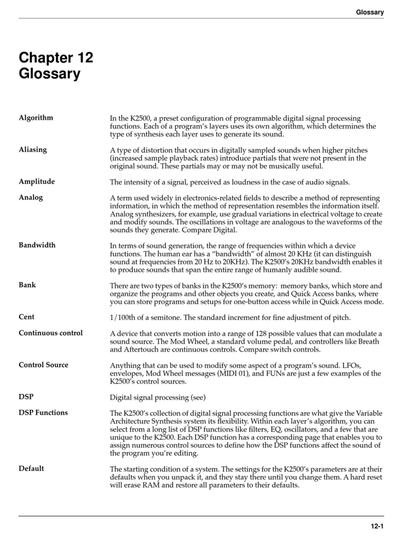
Kurzweil

Kurzweil K2500 - PERFORMANCE GUIDE REV F PART NUMBER 910251 CHAP... User manual

Kurzweil K2600 BEST OF VAST - REV A Technical document

Kurzweil

Kurzweil K2600 BEST OF VAST - REV A Technical document

Kurzweil K2500 User manual

Kurzweil

Kurzweil K2500 User manual
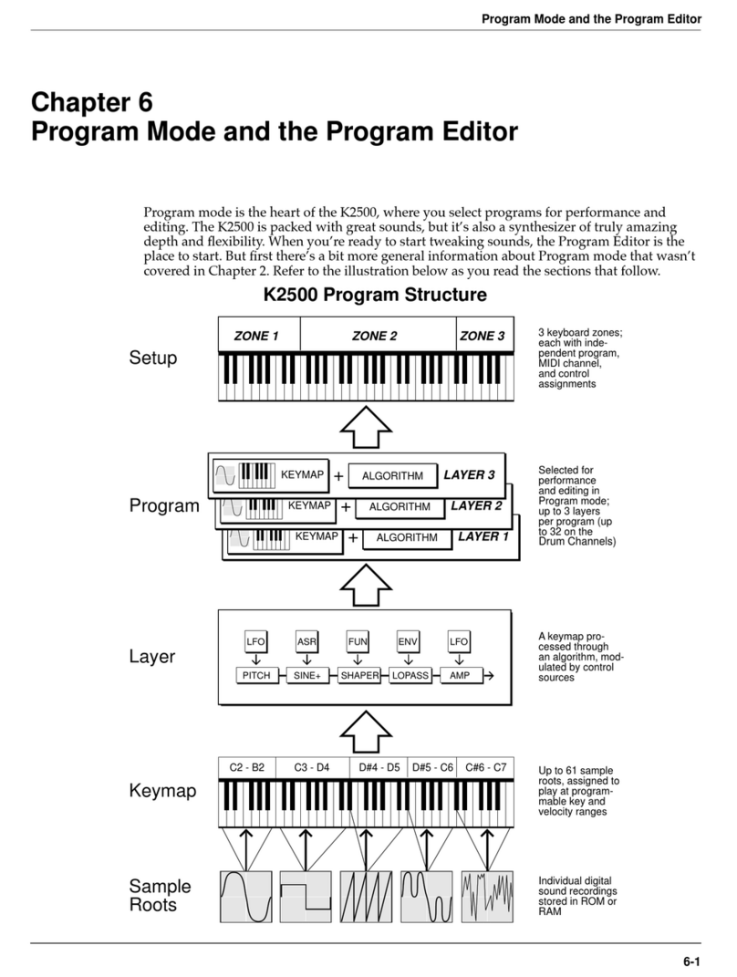
Kurzweil PC88 User manual

Kurzweil

Kurzweil PC88 User manual

Kurzweil MARK 12 V2.0 - ADDENDUM Manual

Kurzweil

Kurzweil MARK 12 V2.0 - ADDENDUM Manual

Kurzweil K2500 User manual

Kurzweil

Kurzweil K2500 User manual

Kurzweil K2500 User manual

Kurzweil

Kurzweil K2500 User manual

Kurzweil K2600 BEST OF VAST - REV A Technical document

Kurzweil

Kurzweil K2600 BEST OF VAST - REV A Technical document

Kurzweil K2500 - PERFORMANCE GUIDE REV F PART NUMBER 910251 CHAP... User manual

Kurzweil

Kurzweil K2500 - PERFORMANCE GUIDE REV F PART NUMBER 910251 CHAP... User manual
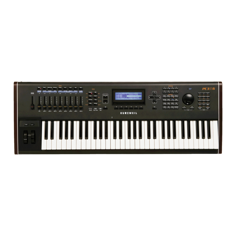
Kurzweil PC3K Series User manual

Kurzweil

Kurzweil PC3K Series User manual

Kurzweil K2600 - MUSICIANS GUIDE REV A PART NUMBER 910330 CHAP... User manual

Kurzweil

Kurzweil K2600 - MUSICIANS GUIDE REV A PART NUMBER 910330 CHAP... User manual
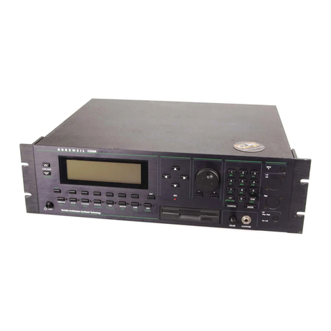
Kurzweil K150 - APPENDIX 1 Technical document

Kurzweil

Kurzweil K150 - APPENDIX 1 Technical document

Popular Synthesizer manuals by other brands

Leipzig TRUE analogue synthesizer user manual

Leipzig

Leipzig TRUE analogue synthesizer user manual

Roland JUNO-X Startup guide

Roland

Roland JUNO-X Startup guide

Yamaha V50 owner's manual

Yamaha

Yamaha V50 owner's manual

Quasimidi Rave-O-Lution 309 owner's manual

Quasimidi

Quasimidi Rave-O-Lution 309 owner's manual

Octave Voyetra Eight Hardware Maintenance Manual

Octave

Octave Voyetra Eight Hardware Maintenance Manual

Alesis Ion supplementary guide

Alesis

Alesis Ion supplementary guide

Waldorf largo user manual

Waldorf

Waldorf largo user manual

Korg 800DV Service manual

Korg

Korg 800DV Service manual

Yamaha SY-77 operating manual

Yamaha

Yamaha SY-77 operating manual

Roland JV80 owner's manual

Roland

Roland JV80 owner's manual

KETRON AUDYA Series instructions

KETRON

KETRON AUDYA Series instructions

Korg monotron owner's manual

Korg

Korg monotron owner's manual

Alesis VI25 user guide

Alesis

Alesis VI25 user guide

Roland Alpha Juno-2 owner's manual

Roland

Roland Alpha Juno-2 owner's manual

Hameg HM8134-3 user manual

Hameg

Hameg HM8134-3 user manual

Roland MKS-70 Service notes

Roland

Roland MKS-70 Service notes

Crumar BIT ONE owner's manual

Crumar

Crumar BIT ONE owner's manual

Yamaha MOXF6 owner's manual

Yamaha

Yamaha MOXF6 owner's manual

manuals.online logo
manuals.online logoBrands
  • About & Mission
  • Contact us
  • Privacy Policy
  • Terms and Conditions

Copyright 2025 Manuals.Online. All Rights Reserved.