DESCRIPTION
The instructions in this manual contain important information on the safe mounting, usage, cleaning and maintenance
of the device. Thus, keep the manual at a place easily accessible by the person who will use the machine, and the
technician.
Mounting, conversions for different gas groups or electrical inlet, and maintenance works of the device should be
performed by a specialist authorized in this subject and in accordance with the instructions of the manufacturer
company.
Gas and electrical connections of the device should be arranged according to the tables and electrical diagram given in
this manual.
Manufacturer company accepts no responsibility for the final damages incurred in humans or properties that are caused
by any procedure not conforming to the instruction manual, or maintenance or technical interventions that are not
performed by authorized people.
TYPES
G7M100G –70 series Pasta Cooker
G9M100G –90 series Pasta Cooker
MOUNTINGINSTRUCTION
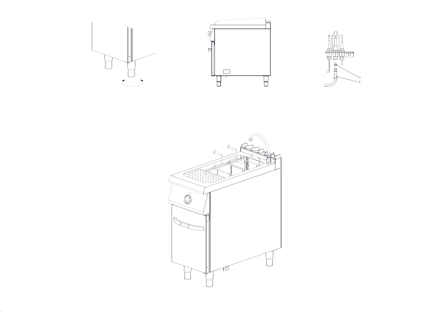
Placement
Place the device beneath a filtered exhaust hood in order to eliminate smell and fume that may be emitted during
cooking.
Place the device at a place min. 10cm away from the side or back wall to prevent excessive temperature rises.
Device should be placed on a flat surface by suitably balancing on the four adjustable legs. (Figure 1)
Remove the protective nylon on the device. Clean the adhesive particles left on the device with a suitable cleaner.
Never leave flammable material near the device.
Gas Connection
Device should be connected in accordance with the national and local gas standards of the relevant country.
Gas inlets of the device are indicated with a (Figure 2) label on device body.
Connection to the gas installation should be made with flex pipe and ball valve. Fix the said ball valve to a place that is
away from heat and easily accessible in case of a danger.
After gas inlet connection is completed, check for possible gas leakages.
Feed the device with the gas and pressure as specified on device information plate and adjusted. If the gas type to
which the device was adjusted for is not suitable to the gas type at the mounted place, follow the instructions written
below.
ATTENTION: All adjustments and modifications to be performed on the
gas installation and connection of the device should be performed by
authorized people. Gas pressure may never exceed 21mbar for Natural gas
and 30mbar for LPG.