manuals.online logo
Brands
  1. Home
  2. •
  3. Brands
  4. •
  5. Kutai electronics
  6. •
  7. Controllers
  8. •
  9. Kutai electronics EA45A220 Series User manual

Kutai electronics EA45A220 Series User manual

KUTAI ELECTRONICS INDUSTRY CO., LTD.
TEL : +886-7-8121771 FAX : +886-7-8121775 Website : www.kutai.com.tw
Headquarters : No.3, Ln. 201, Qianfu St., Qianzhen Dist., Kaohsiung City 80664, Taiwan
EA45A220
Generator Automatic Voltage Regulator
Operation Manual
Self Excited Automatic Voltage Regulator
45 Amp AVR for Carbon Brush Type Generators
EA45A220HL (Half Wave) / EA45A220FL (Full Wave)
*Parallel version is available for option
___________________________________________________________________________________________
2EA45A220
SECTION 1 : SPECIFICATION
Sensing & power Input
Under FrequencyProtection(FactoryKneePoint Setting)
Voltage 170 –265 Vac, 1 phase 2 wire
50 Hz system presets knee point at 45 Hz
Frequency 50 / 60 Hz selectable
60 Hz system presets knee point at 55 Hz
Output (at 220 Vac input)
Environment
Voltage EA45A220HL(Half-wave) Max.90 Vdc
Operation Temperature -40 +60 ˚C
EA45A220FL(Full-wave) Max.180 Vdc
Storage Temperature -40 +85 ˚C
Current Continuous 45A
Relative Humidity Max. 95%
Intermittent 60A for 10 sec.
Vibration 3 Gs @ 100 2K Hz
Resistance EA45A220HL Min. 1.4 ohms
EA45A220FL Min. 2.7 ohms
Cooling condition
Forced with 120.0 (L) x 120.0 (W) x 38.0 (H) mm fan
Voltage Regulation
< +/- 1% ( with 4% engine governing )
Dimensions
330.0 (L) x 189.0 (W) x 180.0 (H) mm
Build Up Voltage
Residual voltage at AVR terminal > 5 Vac @ 25 Hz
Weight
EA45A220HL 4.5 kgs +/- 2%
External Volts Adjustment
EA45A220FL 5.2 kgs +/- 2%
+/- 6%
189.0
330.0
180.0
160.0
169.0
12
Unit : mm
150.0
SECTION 2 : ADJUSTMENT
POWER LAMP
Lights up when AVR is powered.
VOLT Voltage Adjustment
Generator output voltage adjustment.
AUTOMATIC
VOLTAGE REGULATOR
U/F LAMP
POWER LAMP
F S +HI LO
STAB. VOLT. U/F
STAB Stability Adjustment
Correct stability adjustment must be
conducted while the generator is operating
without load. First adjust this STAB (POT)
anti-clockwise until the voltage becomes
unstable, and then slightly adjust it clockwise
(about 1/5 turn). When the voltage just
reaches the critical point (knee point) of
stabilization, where the voltage is stable yet
very close to becoming unstable.
U/F LAMP
Lights up when the generator is in U/F (Under
Frequency Protection)
Select frequency 50 or 60Hz according to the
generator in use(refer to section 4)
U/F Under Frequency
Protection Adjustment When generator speed
falls below the knee point, the under frequency
protection circuit will activate and the voltage
begin to decrease in linear descend.
Adjustment
Figure 2
Outline Drawing
Figure 1
___________________________________________________________________________________________
EA45A220 3
Figure 5
Figure 3
Figure 6 Manual Field Flash
SECTION 3 : WIRING CONNECTION
G
~
Field
BATT.FIELDPOWER
EA45A220
220VAC
T
S
F-
F+ B+ B-
R
SECTION 4 : FREQUENCY SELECTION
AND KNEE POINT ADJUSTMENT
4.1 Frequency Selection
Detach the controller from enclosure(refer to Figure 4)
and select the system frequency on the back of the
controller(refer to Figure 5).
J1
EA45AF PCB
VR
Black
Magenta
Yellow
Red
14
3
2
J1
J2
Close : 60Hz
HZHZ
Open : 50Hz
Pink
Blue
White
76
5
EXT. VR
VR
1K Ohm
close :enable Low frequency protection
open :disable Low frequency protection
(Reverse Side)
4.2 Knee Point Adjustment
4.2.1 Turn the U/F POT fully clockwise.
4.2.2 Adjust VOLT POT to nominal level and speed
down the engine to knee point.
4.2.3 Turn the U/F POT counter-clockwise until the
voltage starts to decrease (U/F lamp illuminates),
re-adjust engine speed to rated speed.
SECTION 5 : FIELD FLASHING
When the regulator is installed correctly but the
generator is failed to generate power. Besides carbon
brushes were worn out, here are two possible causes
below.
5.1 The polarity of field is inverse
Solution:Exchange the connection of F+ and F-.
5.2 The residual voltage is less than 5 Vac,
Solution 1:
5.2.1 Shut down generator, disconnect the wiring
between AVR and generator then flash the field.
Flashing duration = 3 seconds. (See wiring in
Figure 6)
Resistor 3 –5 ohms for full wave AVR
Resistor 5 –10 ohms for half wave AVR
Warning!! Over field flashing may damage
the field winding of generator.
5.2.2 Restart generator and measure the residual
voltage by AC Voltmeter, if it is still less than 5
Vac, repeat the previous process, after several
times, the residual voltage still cannot be built,
Kutai EB500 is strongly recommended, see
Figure 6.
Field
SWR
-+
V
F+F-
BATT.
~
G
~
T
S
R
Figure 4
Fig. 6
___________________________________________________________________________________________
4EA45A220
Solution 2 : Install Kutai automatic flash module
EB500
G
~
Field
T
S
R
BATT.FIELDPOWER
EA45A220
220VAC F-
F+ B+ B-
-+
EB500
F-F+ B+
B-
ACC1 ACC2
fuel switch(N.O.)
BATT.
Oll pressure or
WARNING
This Automatic Voltage Regulator is not
equipped with loss-Sensing Protection function /
Over Excitation Protection. An additional
Over-Voltage Protection device for load may be
required to avoid possible damage to the
equipment or severe personal injury or death.
ATTENTION
1. AVR installation should only be performed by
a qualified technician.
2. Install AVR inside the generator control panel
to avoid high temperature, moisture, and
location where AVR cannot be easily reached.
3. AVR heat sink may reach a high temperature
(above 60 ˚C) when AVR is powered, do not
touch or ground AVR heat sink.
4. Make sure you have read and understand the
contents of the instruction manual prior to
installation. Incorrect wiring connection may
result in irreversible damage to the product
and other equipments.
SECTION 6 : TROUBLE SHOOTING
SYMPTOM
POSSIBLE CAUSES
SOLUTIONS
Voltage does not
build up
Residual voltage below 5 Vac
Field flash is required
Incorrect wiring
Check wiring diagram for proper connection
Engine under speed
Increase engine speed to above 25 Hz
Carbon brushes were worn out
Replace with new carbon brushes
Low output voltage
Voltage set point is not properly adjusted
Adjust VOLT POT clockwise to reach
desired voltage
External voltage adjusted too low
Turn the external VR to reach desired
voltage
Under Frequency Protection is activated
Refer to Section 4 Frequency selection and
knee point adjustment
Over output voltage
Voltage set point is not properly adjusted
Adjust VOLT POT anti-clockwise to reach
rated voltage
Output voltage
unstable (Hunting)
Stability range is not set properly
Refer to Section 2 Adjustment
Field voltage or field resistance is too low
Connect suitable resistor in series to
increase total resistance
※Appearance and specifications of products are subject to change for improvement without prior notice.
Figure 7

This manual suits for next models

2

Other Kutai electronics Controllers manuals
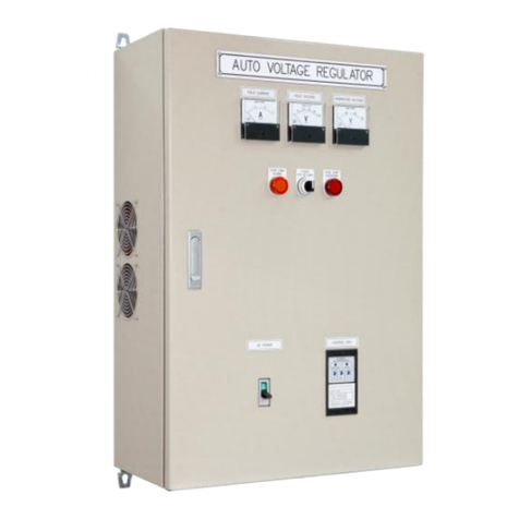
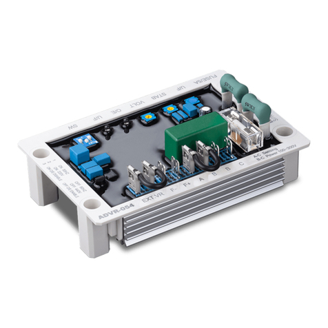
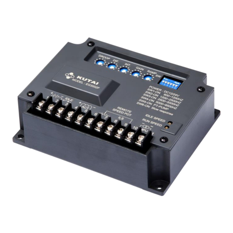
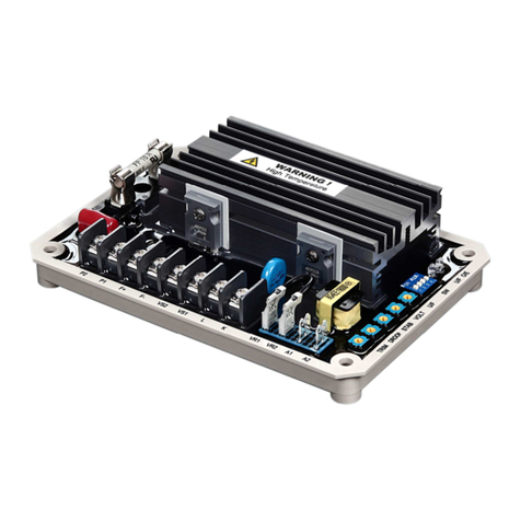
Kutai electronics ADVR-054 User manual

Kutai electronics

Kutai electronics ADVR-054 User manual

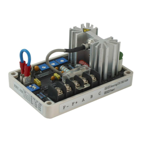
Kutai electronics EA200A User manual

Kutai electronics

Kutai electronics EA200A User manual
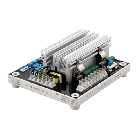
Kutai electronics ADVR-16-400HZ User manual

Kutai electronics

Kutai electronics ADVR-16-400HZ User manual

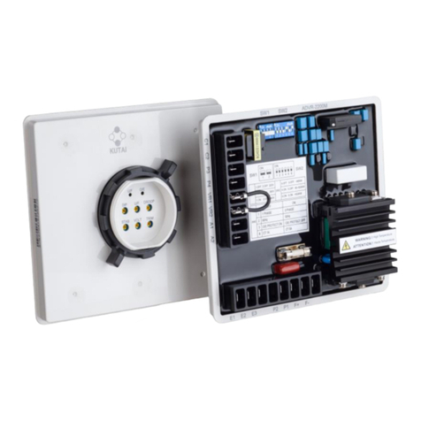
Kutai electronics ADVR-2200M User manual

Kutai electronics

Kutai electronics ADVR-2200M User manual

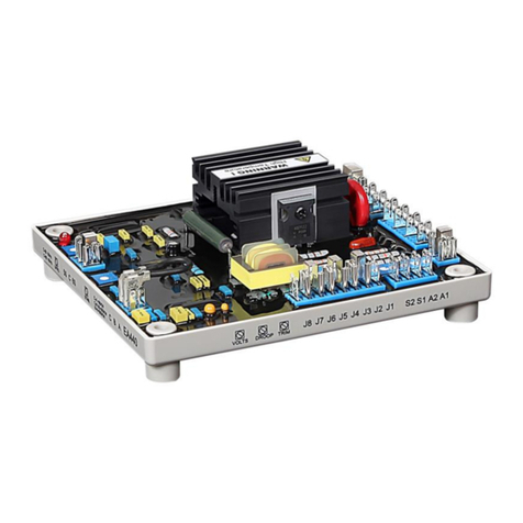
Kutai electronics EA440 User manual

Kutai electronics

Kutai electronics EA440 User manual

Kutai electronics ADVR-083-400HZ User manual
Kutai electronics

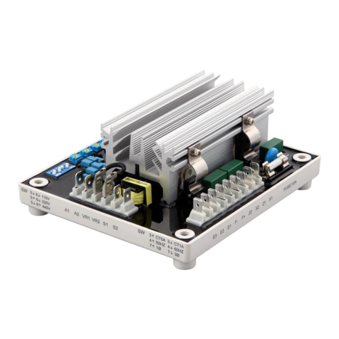
Kutai electronics ADVR-083-400HZ User manual

Kutai electronics EA05A User manual

Kutai electronics

Kutai electronics EA05A User manual

Kutai electronics EA63-2.5 User manual

Kutai electronics

Kutai electronics EA63-2.5 User manual

Kutai electronics ADVR-12 User manual

Kutai electronics

Kutai electronics ADVR-12 User manual

Kutai electronics EG3002 User manual

Kutai electronics

Kutai electronics EG3002 User manual

Kutai electronics EA16 User manual

Kutai electronics

Kutai electronics EA16 User manual

Kutai electronics ADVR-073 User manual

Kutai electronics

Kutai electronics ADVR-073 User manual

Kutai electronics EA06 User manual

Kutai electronics

Kutai electronics EA06 User manual

Kutai electronics EA448B User manual

Kutai electronics

Kutai electronics EA448B User manual

Kutai electronics EA350 User manual

Kutai electronics

Kutai electronics EA350 User manual

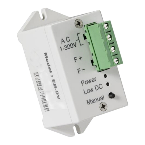
Kutai electronics EB-9V User manual

Kutai electronics

Kutai electronics EB-9V User manual

Kutai electronics ADVR-083 User manual
Kutai electronics

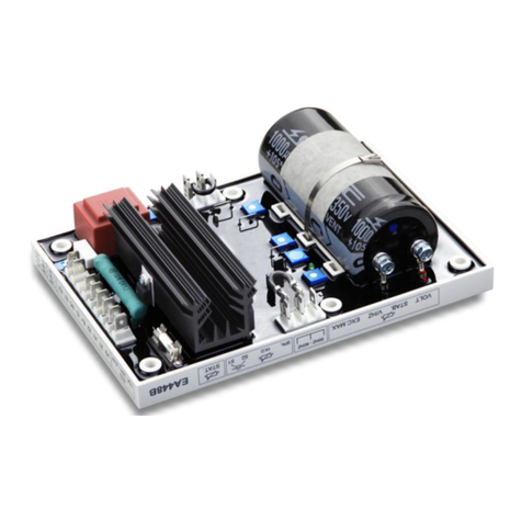
Kutai electronics ADVR-083 User manual

Kutai electronics EA125-8 User manual

Kutai electronics

Kutai electronics EA125-8 User manual

Kutai electronics EA05A User manual

Kutai electronics

Kutai electronics EA05A User manual
Kutai electronics ADVR-2300M User manual

Kutai electronics

Kutai electronics ADVR-2300M User manual

Kutai electronics EA04C User manual

Kutai electronics

Kutai electronics EA04C User manual

Kutai electronics EA42-7 User manual

Kutai electronics

Kutai electronics EA42-7 User manual

Kutai electronics EG3002F User manual

Kutai electronics

Kutai electronics EG3002F User manual

Kutai electronics ADVR-073 User manual
Kutai electronics

Kutai electronics ADVR-073 User manual

Popular Controllers manuals by other brands

ZESTA BENCHTOP CONTROLLER quick start guide

ZESTA

ZESTA BENCHTOP CONTROLLER quick start guide

Smartgen ALC404 user manual

Smartgen

Smartgen ALC404 user manual

HUAYUAN MAM860 Operation manual

HUAYUAN

HUAYUAN MAM860 Operation manual

KAEL Muhendislik Elektronik VARkombi-PC user manual

KAEL Muhendislik Elektronik

KAEL Muhendislik Elektronik VARkombi-PC user manual

MFJ Memory Keyer MFJ-493 instruction manual

MFJ

MFJ Memory Keyer MFJ-493 instruction manual

RR-Concepts StationMaster-5 manual

RR-Concepts

RR-Concepts StationMaster-5 manual

Majestic MPPT Series user manual

Majestic

Majestic MPPT Series user manual

WaterLine Controls WLC-9000 installation instructions

WaterLine Controls

WaterLine Controls WLC-9000 installation instructions

rotork LP/S Series Installation, Comissioning and maintenance manual

rotork

rotork LP/S Series Installation, Comissioning and maintenance manual

DUOmetric LVB technical information

DUOmetric

DUOmetric LVB technical information

gefran GFW-Xtra 40 Installation and operation manual

gefran

gefran GFW-Xtra 40 Installation and operation manual

Fisher 1032 instruction manual

Fisher

Fisher 1032 instruction manual

Unitronics Vision120 installation guide

Unitronics

Unitronics Vision120 installation guide

Honeywell TPPL Modbus TCP Installation and setup guide

Honeywell

Honeywell TPPL Modbus TCP Installation and setup guide

Kohler APM303 user manual

Kohler

Kohler APM303 user manual

Datapath Fx4 quick start guide

Datapath

Datapath Fx4 quick start guide

Emerson Fisher 627 instruction manual

Emerson

Emerson Fisher 627 instruction manual

Headend Products Remote Kontrol user manual

Headend Products

Headend Products Remote Kontrol user manual

manuals.online logo
manuals.online logoBrands
  • About & Mission
  • Contact us
  • Privacy Policy
  • Terms and Conditions

Copyright 2025 Manuals.Online. All Rights Reserved.