manuals.online logo
Brands
  1. Home
  2. •
  3. Brands
  4. •
  5. Kutai electronics
  6. •
  7. Controllers
  8. •
  9. Kutai electronics EA230 User manual

Kutai electronics EA230 User manual

KUTAI ELECTRONICS INDUSTRY CO., LTD.
TEL : +886-7-8121771 FAX : +886-7-8121775 Website : www.kutai.com.tw
Headquarters : No.3, Ln. 201, Qianfu St., Qianzhen Dist., Kaohsiung City 80664, Taiwan
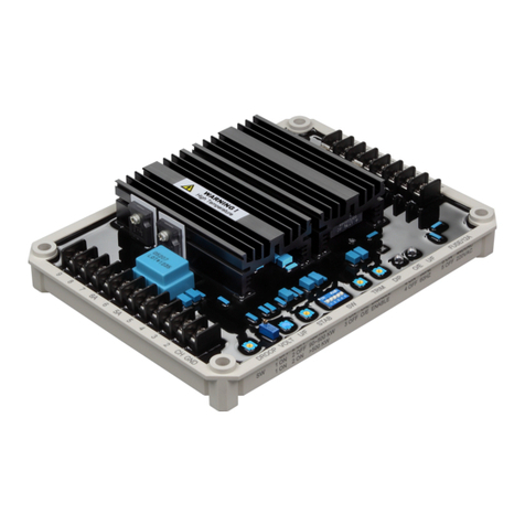
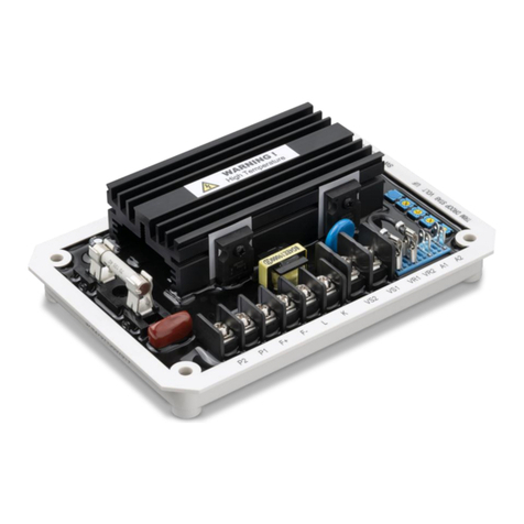
EA230
Generator Automatic Voltage Regulator
Operation Manual
Self ExcitedAutomatic Voltage Regulator
Compatible with Leroy Somer R230*
* All manufacturer names and numbers are used for reference purpose only
and do not imply that any part is the product of these manufacturer.
___________________________________________________________________________________________
2EA230
SECTION 1 : SPECIFICATION
Sensing Input
Static Power Dissipation
Voltage 90 140 Vac @ 120 Vac
Max.6 watts
1 phase 2 wire
Frequency 50/60 Hz
Under Frequency Protection (Factory Presets)
Adjustable range 45/55 Hz
Excitation Output
Voltage Max. 100 Vdc @ power input 120 Vac
Voltage Thermal Drift
Current Continuous 3.5A
Less than 3% at temperature range -40 to +70 ˚C
Intermittent 5A for 10 secs.
Resistance Min. 15 ohms
Environment
Fuse Spec. Slow blow 5 x 20mm UDA-8A / 250V
Operating Temperature -40 to +60 ˚C
Storage Temperature -40 to +85 ˚C
External Voltage Adjustment
Relative Humidity Max. 95%
Max. +/- 5% @ 1K ohm 0.5 watt potentiometer
Vibration 1.5 Gs @ 5 –30 Hz
5.0 Gs @ 30 –500 Hz
Voltage Regulation
Less than +/- 1% ( with 4% engine governing )
Dimensions
140.0 (L) x 75.0 (W) x 51.0 (H) mm
Build Up Voltage
6 Vac residual volts at power input terminal
Weight
310 g +/- 2%
EMI Suppression
Internal electromagnetic interference filtering
ATTENTION
1. AVR can be mounted directly on the
engine, genset, switchgear, control panel,
or any position that will not affects
operation. For dimension reference, please
see Figure 1.
2. All voltage readings are to be taken with an
average-reading voltmeter Meggers and
high-potential test equipment must not be
used. Use of such equipment could
damage the AVR.
3. Terminal:"Fast-On" terminals 6.35mm (1/4
inch)
4. Improper setting of under-frequency
protection could cause the output voltage
of the unit to drop or become unstable
under with changes in load. Avoid making
any changes to the U/F setting unless
necessary.
VOLT
STAB
U/F
50.0
75.0
140.0
115.0
51.0
FUSE
8A
110V 0V E+ E-
VR HZ
18.0
5.8
Figure 1 Outline Drawing
___________________________________________________________________________________________
EA230 3
SECTION 2 : WIRING
2.1 Operation
The following system operation procedures provide
instructions for adjusting the EA230 voltage regulator.
Symptoms resulting from a faulty regulator and certain
generator system problems are included, together with
suggested remedies.
2.2 Wiring (Refer to Figure 2, 3)
2.2.1 Connect E+1, E- to DC output port.
2.2.2 Connect the sensing port at 100V, 0V
2.2.3 External voltage regulator is as Figure 2, 3
Complete the following steps before proceeding with
the system start-up.
ATTENTION
Meggers and high potential test equipment must
not be used. Incorrect use of such equipment
could damage the semiconductors contained in
the regulator.
2.3 Preliminary SET-UP
2.3.1 Verify that the voltage regulator specifications
conform with the generator system requirements.
2.3.2 Ensure the voltage regulator is correctly
connected to the generator system.
2.3.3 Install the correct fuse (8A / 250V) to prevent
damage caused from short circuit.
2.3.4 Set the regulator 「VOLT」and external 「VOLT
ADJ」( if used ) as follows:
Regulator 「VOLT」: Fully CCW
Remote 「VOLT」: Centered
2.3.5 Adjust the front panel STAB control that controls
the system stability. Rotation of the front panel
STAB control in the counter-clockwise (CCW)
direction will speed up response time and if over
rotated in CCW direction, the generator voltage
may oscillate (hunt).
2.3.6 Rotated the front panel STAB control CCW until
the system start oscillating and then rotate CW
just past the point where oscillation occurred.
2.4 System START-UP
2.4.1 Perform preliminary set-up as described in the
above paragraphs.
ATTENTION
The AVR reading AC voltage are all average
value.
2.4.2 Start prime mover and bring up to rated speed.
RESULT :
Voltage should build up. If not, perform Field Flashing.
2.4.3 Slowly adjust the regulator「VOLT」CW until the
generator output voltage reaches the nominal
value. If used, adjust the remote 「VOLT」to set
the generator voltage to the exact value desired.
RESULT :
Voltage should build up to rated value. If voltage does
not build up to the rated value, check generator for
short or excessive load.
2.4.4 Check regulator under normal operating and
loading conditions.
RESULT :
Voltage regulation should be better than +/- 1.0%
no-load to full-load. If regulation is not within this range,
perform the following steps :
(1) Voltage reduction under load may be due to speed
change from no load to full load. causing the
frequency compensation (V/Hz) circuit to reduce
voltage at lower frequencies.
(2) Replace voltage regulator.
2.5 Operational Test
2.5.1 Connect the test setup as shown in the following
figure, Operational Test. Do not apply power.
Ensure that the light bulb is rated for 120V and is
less than 100W.
2.5.2 Adjust the regulator「VOLT」or remote「VOLT」
to maximum CW.
2.5.3 Apply 120V, 50/60 Hz power to the regulator. The
light bulb should illuminate
2.5.4 Slowly adjust the regulator 「VOLT」control
CCW. At the regulation point, the light bulb
should extinguish.
___________________________________________________________________________________________
4EA230
VR VR
RHEOSTAT
1K 0.5W
EXTERNAL
VOLT. ADJ.
EA230
E+ E-
FIELD
EXC.
110V 0V
T
S
N
R
Open 60Hz
Close 50Hz
HZ
HZ
T
S
N
HZ
EA230
E+
110V 0V VR
E- VR
EXC.
FIELD
EXTERNAL
VOLT. ADJ.
RHEOSTAT
1K 0.5W
HZ
Open 60Hz
Close 50Hz
Interconnection Diagram, 120 / 208 V Nominal,
3-Phase, 4-Wire
Figure 2
Interconnection Diagram, 120 / 240 V Nominal,
1-Phase, 3-Wire
Figure 3
FIELD
WARNING
Please make sure you have read and understand the
contents of the instruction manual prior to
installation. Incorrect wiring connection may result
in irreversible damage to the product and other
equipments.
This Automatic Voltage Regulator is not equipped
with loss-Sensing Protection function / Over
Excitation Protection. An additional Over-Voltage
Protection device for load may be required to avoid
possible damage to the equipment or severe
personal injury or death.
Operational Test
Figure 4
※Use only the replacement fuses specified in this user manual.
※Appearance and specifications of products are subject to change for improvement without prior notice.

Other Kutai electronics Controllers manuals

Kutai electronics EA04C User manual

Kutai electronics

Kutai electronics EA04C User manual

Kutai electronics ADVR-054 User manual

Kutai electronics

Kutai electronics ADVR-054 User manual

Kutai electronics EA125-8 User manual

Kutai electronics

Kutai electronics EA125-8 User manual

Kutai electronics ADVR-250 User manual

Kutai electronics

Kutai electronics ADVR-250 User manual

Kutai electronics EA45A220 Series User manual

Kutai electronics

Kutai electronics EA45A220 Series User manual

Kutai electronics ADVR-083-400HZ User manual

Kutai electronics

Kutai electronics ADVR-083-400HZ User manual

Kutai electronics EA200A User manual

Kutai electronics

Kutai electronics EA200A User manual

Kutai electronics EA440 User manual

Kutai electronics

Kutai electronics EA440 User manual

Kutai electronics ATS-34 Ver1.0 User manual

Kutai electronics

Kutai electronics ATS-34 Ver1.0 User manual

Kutai electronics EA05A User manual

Kutai electronics

Kutai electronics EA05A User manual

Kutai electronics EA341 User manual

Kutai electronics

Kutai electronics EA341 User manual

Kutai electronics EA05A User manual

Kutai electronics

Kutai electronics EA05A User manual

Kutai electronics ADVR-083 User manual

Kutai electronics

Kutai electronics ADVR-083 User manual

Kutai electronics ADVR-2200M User manual

Kutai electronics

Kutai electronics ADVR-2200M User manual

Kutai electronics ADVR-053 User manual

Kutai electronics

Kutai electronics ADVR-053 User manual

Kutai electronics EG3002F User manual

Kutai electronics

Kutai electronics EG3002F User manual

Kutai electronics EA16 User manual

Kutai electronics

Kutai electronics EA16 User manual

Kutai electronics EA350 User manual

Kutai electronics

Kutai electronics EA350 User manual

Kutai electronics EG3002 User manual

Kutai electronics

Kutai electronics EG3002 User manual

Kutai electronics EA321 User manual

Kutai electronics

Kutai electronics EA321 User manual

Kutai electronics ADVR-12 User manual

Kutai electronics

Kutai electronics ADVR-12 User manual

Kutai electronics ADVR-073 User manual

Kutai electronics

Kutai electronics ADVR-073 User manual

Kutai electronics ADVR-2300M User manual

Kutai electronics

Kutai electronics ADVR-2300M User manual

Kutai electronics ADVR-16 User manual

Kutai electronics

Kutai electronics ADVR-16 User manual

Popular Controllers manuals by other brands

Geco GH10TA user manual

Geco

Geco GH10TA user manual

Solar Next chillii Installation and operating manual

Solar Next

Solar Next chillii Installation and operating manual

Tyco iSTAR Ultra G2 SE quick start guide

Tyco

Tyco iSTAR Ultra G2 SE quick start guide

Siegenia Drive Connect Box Installation and operating instructions

Siegenia

Siegenia Drive Connect Box Installation and operating instructions

Bosch BAT 251 Original instructions

Bosch

Bosch BAT 251 Original instructions

GE PACSystems* RX3i user manual

GE

GE PACSystems* RX3i user manual

SpeedyBee F405 V4 BLS 55A 30x30 Stack user manual

SpeedyBee

SpeedyBee F405 V4 BLS 55A 30x30 Stack user manual

Johnson Controls T-5800 Series Installation and Calibration

Johnson Controls

Johnson Controls T-5800 Series Installation and Calibration

Nelson WINDOW+ user guide

Nelson

Nelson WINDOW+ user guide

Extron electronics HD CTL 100 Setup guide

Extron electronics

Extron electronics HD CTL 100 Setup guide

Timotion MA2 user manual

Timotion

Timotion MA2 user manual

Carrier MINIMUM LOAD CONTROL ACCESSORY 30XA080-500 installation instructions

Carrier

Carrier MINIMUM LOAD CONTROL ACCESSORY 30XA080-500 installation instructions

Triple Plus CLM-IRAMAP-1-02 quick start guide

Triple Plus

Triple Plus CLM-IRAMAP-1-02 quick start guide

SITEK SlickDevice S1 owner's manual

SITEK

SITEK SlickDevice S1 owner's manual

Siemens GDB 1 Series Mounting instructions

Siemens

Siemens GDB 1 Series Mounting instructions

PPI claveX Series user manual

PPI

PPI claveX Series user manual

Tempco TPC20052 user manual

Tempco

Tempco TPC20052 user manual

Lionel TMCC manual

Lionel

Lionel TMCC manual

manuals.online logo
manuals.online logoBrands
  • About & Mission
  • Contact us
  • Privacy Policy
  • Terms and Conditions

Copyright 2025 Manuals.Online. All Rights Reserved.