KV2 Audio ESR215 Mk II User manual

User Guide
ESR Series
The Future of Sound.
Made Perfectly Clear.
At KV2 Audio our vision is to constantly develop technologies
that eliminate distortion and loss of information providing
a true dynamic representation of the source.
Our aim is to create audio products that absorb you,
place you within the performance and deliver a listening
experience beyond expectations.
ESR2800 · ESR212 / ESR3000MkII · ESR215MkII

ESR Series · Important Safety Instructions
Important Safety Instructions
Before using your ESR Series, be sure to carefully read the applicable items of these operating instructions
and the safety suggestions.
1. Read all product instructions.
2. Keep printed instructions, do not throw away.
3. Respect and rewiew all warnings.
4. Follow all instructions.
5. Do not use this unit near water, in unprotected out door areas or in rain or wet conditions.
6. Clean only with dry cloth.
7. Do not block any ventilation openings.
8. Install in accordance with KV2 Audio's recommended installation instructions.
9. Do not install near any heat sources such as heat radiators, heat registers, stoves or other apparatus
that produce heat.
10. Do not defeat the safety purpose of the grounding type plug. A grounding type plug has two blades
and a third grounding connector. The third connector is provided for your safety. If the provided plug
does not t into your outlet, consult an electrician for replacement of the obsolete outlet.
11. Protect the power cord from being walked on or pinched, particularly at plugs, convenience receptacles.
The AC mains plug or appliance coupler shall remain readily accessible for operation.
12. Only use accessories specied by KV2 Audio.
13. Install the product only with rigging specied by KV2 Audio, or sold with the loudspeaker.
14. Unplug this loudspeaker during lightning storms or when unused for long periods of time.
15. Refer all servicing to qualied service personnel. Servicing is required when the loudspeaker has been
damaged in any way, such as when the power-supply cord or plug has been damaged; liquid has been
spilled or objects have fallen into the loudspeaker; rain or moisture has entered the loudspeaker;
the loudspeaker has been dropped; or when for undetermined reasons the loudspeaker does not operate
normally.
16. Do not remove front or back panels. Removal of the panel will expose hazardous voltages.
There are no user serviceable parts inside and removable may void the warranty.
17. An experienced user shall always supervise this professional audio equipment.
CAUTION: TO REDUCE THE RISK OF ELECTRIC SHOCK, DO NOT REMOVE THE PANELS.
NO USER-SERVICEABLE PARTS INSIDE. REFER SERVICING TO QUALIFIED PERSONNEL.
WARNING: To prevent re or electric shock, do not expose this equipment to rain or moisture.
SAFETY SUMMARY
To reduce the risk of electric shock, disconnect the loudspeaker from the AC mains before installing audio cable.
Reconnect the power cord only after making all signal connections. Connect the loudspeaker to a twopole, three- wire
grounding mains receptacle. The receptacle must be connected to a fuse or circuit breaker. Connection to any other
type of receptacle poses a shock hazard and may violate local electrical codes. Do not allow water or any foreign object
to get inside the loudspeaker. Do not put objects containing liquid on or near the unit. To reduce the risk of overheating the
loudspeaker, avoid exposing it to direct sunlight. Do not install the unit near heat-emitting appliances, such as a room heater
or stove. This loudspeaker contains potentially hazardous voltages. Do not attempt to disassemble the unit. The unit contains
no user serviceable parts, repairs should be performed only by factory trained service personnel.
ESR Series · Important Safety Instructions

ESR Series · Contents
Introduction ESR Series / ESR Brackets and Flybars 5 - 6
Introduction 5 - 6
ESR2800/3000MkII 7
Overview 7
Getting Started 8 - 9
Features - Front panel 10
Features - Rear panel 11 - 12
Using the System - ESR2800 13 - 14
Using the System - ESR3000MkII 15 - 16
Specications 17 - 18
Block Diagram 19 - 20
Drawing 21 - 22
ESR212 23
Overview 23
Technology 24
Specications 25
Frequency characteristics 26
Drawing 27
ESR215MkII 28
Overview 28
Technology 29
Specications 30
Frequency characteristics 31
Drawing 32
Accessories 33 - 35
ESR Brackets and Flybars · Instructions 36
Warranty · Service 37
Notes 38
Contents
ESR Series · Contents

ESR Series · Introduction
Introduction
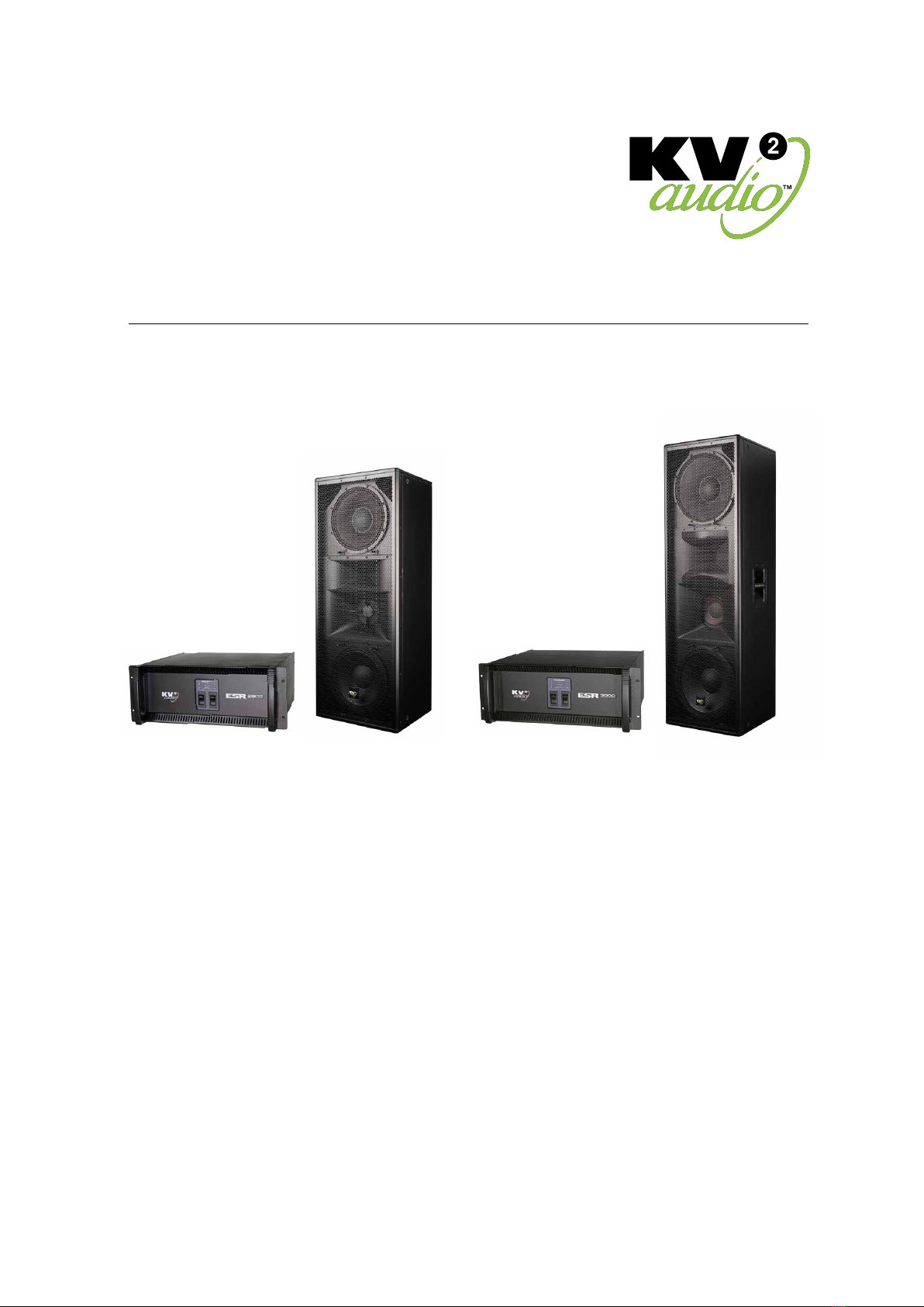
Thank you for purchasing this KV2 Audio, ESR Series system, consisting of the ESR2800/3000MkII stereo controller/amplier
unit, two ESR212/215MkII speakers and optional variants of subwoofers.
The ESR range has been developed for a particular niche in the market, where an all in one box is needed to give clear
detailed reproduction over a wide area. The ESR212 and 215MkII are three way full range enclosures with wide dispersion
characteristics. They can be used vertically for theatre, church or cultural centre type installations, or horizontally mounted
to give excellent coverage over a tiered seating area for stadium or grandstand type applications.
Similar to our popular ES range, the ESR cabinets are fully active and driven by a proprietary amplier, which delivers
equalized, and time aligned accurate signal to each of the components. Two ESR212 cabinets can be driven by a single
ESR2800 High Denition Amplier (analogically with ESR215MkII's and ESR3000MkII), which houses all signal processing and
amplication, as well as providing control for two dierent external subwoofer cabinet congurations if required.
In situations where extended bass response is not needed, but full range high denition audio reproduction with extremely
good coverage is required, the ESR Range oers an ideal solution. Economies of scale are achieved by the requirement
of only one ESR amplier, to run a three way active stereo system where other systems would require processors and multiple
ampliers to achieve a similar conguration.
This manual contains important information on operating the ESR system correctly and safely. Please take some time
and read this manual to familiarize yourself with the advanced features of this system.
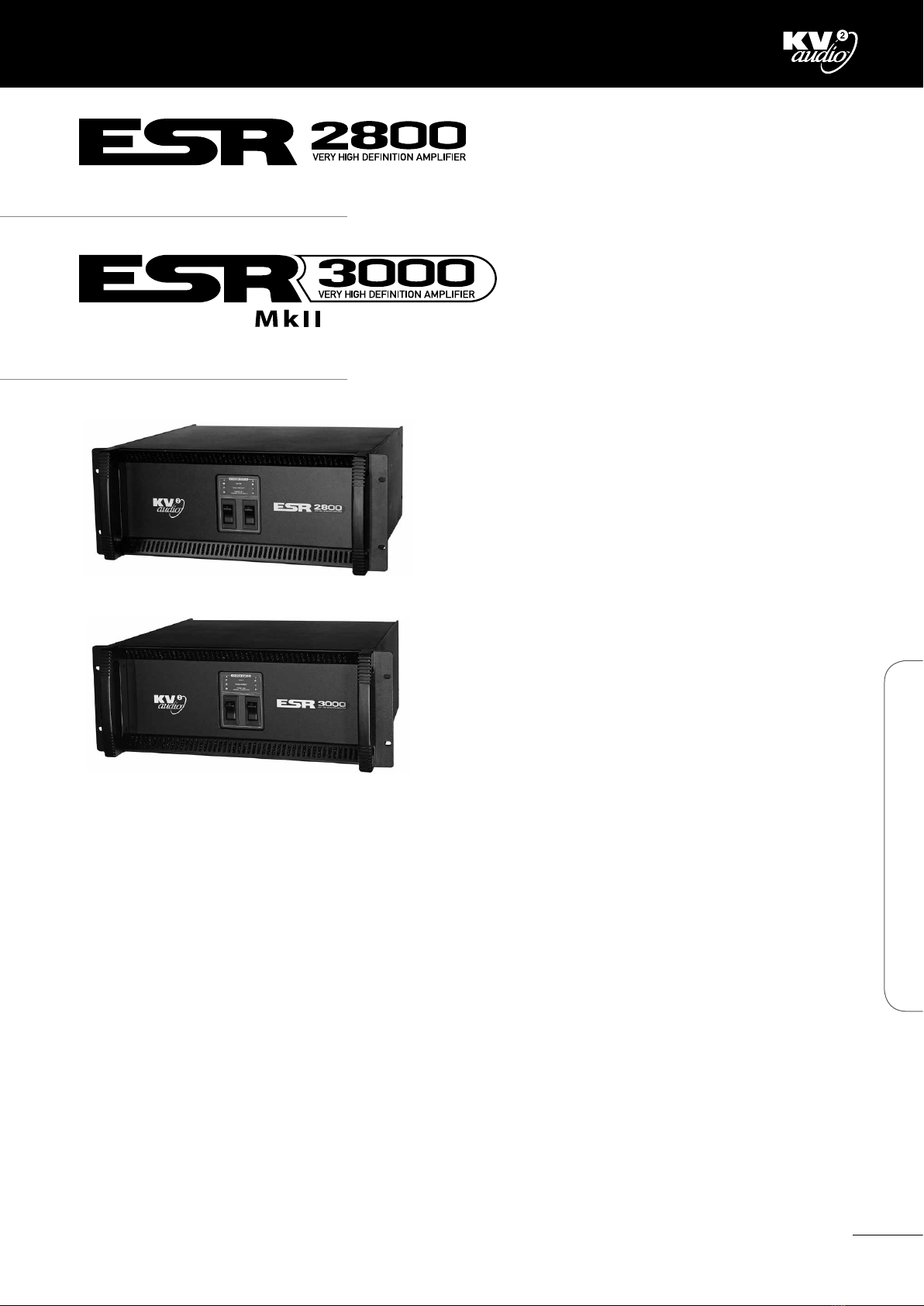
The ESR2800/3000MkII Amplier is a three-way, active control and amplication system, specically designed for the KV2
Audio ESR series loudspeaker systems. It houses all signal processing and amplication, as well as providing control for
external subwoofer cabinet congurations, and to operate additional subwoofer cabinets if needed. External subwoofers are
powered by the external subwoofer amplier (VHD3200).
The amplier compliment and conguration inside the ESR2800/3000MkII Amplier is as follows:
High Frequency - 100-watt, Class AB, Push pull, Low intermodulation design.
Mid Frequency - 200-watt, Class AB, Push pull, Low intermodulation design.
Low Frequency - 1000-watt, High-eciency, Current-enhancing switch mode technology with Linear Active Filter.
In most cases it would be advisable to use a KV2 Audio Line driver (LD4) in addition at the mixer end, to ensure that the line
to the amplier is driven correctly and the signal integrity maintained.
Although this system is simple to operate, improper use can be dangerous. This is a very high-powered device that can put
out high voltages and sizeable currents. Always use safe operating techniques with the ESR Series system.
Important notice
As part of KV2's constant programme of improvement and upgrades, there are now two versions of the ESR215 and ESR3000.
The current version are identied as ESR215MkII and ESR3000MkII, (with serial numbers that start from B26Q010159
for the ESR215MkII and all ESR3000MkII ampliers begin with the serial numbers A16P090091.
The Technical dierences between old and new ESR215MkII are:
The original version is complemented with 4 OHM woofers and are wired internally in series.
The new version MkII has 16 OHM woofers and are wired in parallel.
It is important to use new version of ESR3000MkII ampliers with ESR215MkII for correct response and operation
and not to mix old and new.
FOR YOUR SAFETY, READ THE IMPORTANT PRECAUTIONS SECTION AS WELL AS THE INPUT, OUTPUT AND POWER
CONNECTION SECTIONS OF THIS MANUAL.
ESR Series · Introduction
5

ESR Brackets and Flybars · Introduction · Warning
Introduction
This manual is presented by KV2 Audio, to enable the clear and precise instructions for the safe practice and execution
of overhead suspension, or ying of the KV2 Audio ESR Full range Loudspeaker products, using the ESR BRACKETS and FLYBARS.
It is vitally important that operators and users familiarize themselves with all of the components, parts, products and safety
instructions, as described and indicated within this document, before attempting any overhead suspension of the ESR
Brackets and Flybar systems.
The ESR Loudspeaker enclosures are designed with integral suspension points to facilitate secure vertical and Horizontal
suspension and rigging, providing that no modications or external parts are substituted, and that all instructions are
adhered to at all times.
KV2 Audio s.r.o operates a continuing process policy of attaining and improving standards.
This means that instructions and methods may be subject to change without notication, and it is the sole responsibility
of the operator/user to check for any updated information regarding safe stacking and ying procedures whether locally
or Internationally.
Warning - Safety Rigging
There are accepted 'General Rigging Practices' appropriate to the entertainment industry and this Document aims to
encapsulate them specically to the safe vertical and horizontal suspension of the KV2 ESR Loudspeaker systems described here.
It is extremely vital and important that only personnel whom have the qualications and certicates, Prior knowledge and
experience of rigging techniques, attempt the execution of any suspension conguration utilizing the ESR Brackets and
Flybars for the KV2 ESR products.
All advice and instructions expressed and stated within this document, are based upon the highest engineering data
available at the time of publication, from within the Country of manufacture, with regards to materials and general practice
techniques.
Specications are subject to change, due to constant testing, product updates and renements and R&D.
'General Rigging Practices' means that Regulations and requirements are possibly subject to alterations in dierent countries
and may be superseded locally.
KV2 Audio, as such is not responsible for the safety of any suspension, ying overhead of all specic KV2 Audio Loudspeaker
products, or Rigging congurations as executed in practice by users.
It is expressly the sole responsibility of the user to ensure that at all times any KV2 Audio product, or system is Ground
stacked, suspended and rigged in accordance with current International and local regulations.
All non KV2 Audio products such as hoists, clamps, wires, truss, supports used, or required to assure stability, or suspend KV2
Audio Loudspeaker product are the sole responsibility of the user.
Warranty
Your ESR Brackets and Flybars are covered against defects in material and workmanship.
Refer to your supplier for more details.
Service
In the unlikely event that your ESR Brackets and Flybars develop a problem, it must be returned to an authorized distributor,
service center or shipped directly to our factory. Because of the complexity of the design, only qualied technical personnel
must attempt all repairs.
If the unit needs to be shipped back to the factory, it must be sent in its original carton, or suitable alternatives. If improperly
packed, the unit maybe damaged in transit.
To obtain service, contact your nearest KV2 Audio Service Centre, Distributor or Dealer.
ESR Brackets and Flybars · Introduction · Warning
6

ESR2800/3000MkII · Overview
Introduction
The ESR2800/3000MkII is three-way, active control and amplication system specially designed for the KV2 Audio ESR
full range series loudspeaker systems. It houses all signal processing and amplication, as well as providing control and
crossover function an external subwoofer cabinet if needed utilizing an external amplier. The ESR2800 powers the
ESR3000MkII powers the ESR215MkII. Each unit incorporates six ampliers consisting of two 100-watt, Class AB, push pull,
low intermodulation amplier for high frequencies, two 200-watt, Class AB, push pull, low intermodulation design for mids
and two a 1000-watt, high-eciency, current- enhancing switch mode technology amplier for bass. The ESR2800/3000MkII
stereo conguration powers two ESR cabinets accordingly.
ESR2800 - part number KVV 987 285 (250V)
KVV 987 283 (230V)
KVV 987 284 (115V)
ESR3000MkII - part number KVV 987 277 (250V)
KVV 987 276 (230V)
KVV 987 275 (115V)
Application
Intentionally designed for use in Theatres and Cultural
Centers to provide the highest audio quality from single
Column enclosures for stage sides and prosceniums for
medium to larger venues
• Fixed Installations
• Music venues
• Classical and opera concerts
Features
The amplier compliment inside the ESR2800/3000MkII Amplier is as follows:
• High Frequency - 2x 100-watt, Class AB, push pull, low intermodulation design
• Mid Frequency - 2x 200-watt, Class AB, push pull, low intermodulation design
• Low Frequency - 2x 1000-watt, high-eciency, current-enhancing switch mode
ESR2800 Amplier Rack mounted
ESR3000MkII Amplier Rack mounted
7
ESR2800/3000MkII · Overview

ESR2800/3000MkII · Getting Started
Unpacking
Unpack the ESR2800/3000MkII Amplier and check for any damage. If you nd any damage, notify your supplier immediately.
Only the consignee may institute a claim with the carrier for damage incurred during shipping. Be sure to save the carton
and all packing materials for the carrier's inspection. Should you ever need to ship the unit, only use the original factory
packaging. If the shipping carton is unavailable, contact your supplier to obtain a replacement.
The ESR2800/3000MkII Amplier carton should contain:
• ESR2800/3000MkIIAmpliercontrolunit
• Thisuserguide
• TwoPowerCondetachablepowercables
Amplier rack mounting
The ESR2800/3000MkII Amplier is 4 rack units in height and will mount in standard 19" rack systems. Integral rear mounting
rack ears are also provided for additional support, do not rely on xing and mounting the amplier using just the front panel
as support. Use eight screws and washers to mount the amplier to the equipment rack rails. We recommend using a shock
mounted rack for touring use to prolong the life of your amplier.
Rear Panel:
Front Panel:
Side Panel:
Rear Panel:
Front Panel:
Side Panel:
8
ESR2800/3000MkII · Getting Started

ESR2800/3000MkII · Getting Started
Cooling
The ESR2800/3000MkII Amplier has a comprehensive cooling system featuring chassis sealed PCB board mounting and
shock mounted, speed controlled fans. This means that the cooling system never drives air across PCB boards, connectors
or components, ensuring prolonged electronic component lifespan and minimizing maintenance cycles.
Air is drawn into the front of the amplifer by the two fans on the rear panel, this passes over the cooling fans of the heat sinks
and exhausts through the rear. If the heat sink gets too hot, its sensing circuit will open the output relay, disconnecting the load.
It is important to have an adequate air supply at the front of the amplier, and enough space around the rear of the amplier to
allow the cooling air to escape. If the unit is rack mounted, do not use doors or covers on the rear of the rack, the exhaust air must
ow without restriction. If you are using racks with closed backs, use fans on the rear rack panel to ensure an ample air supply.
IMPORTANT! Please note that for correct full performance of the unit AND ANY WARRANTY COVER,
it is important that regular maintenance of the front vents and lters as well as the rear panel fans be inspected
and cleaned by removing any dust and debris build-up. Any product failure due to lack of attention in this matter will
immediately void any current warranty. (Please refer to notes re ventilation procedures).
AC Requirements
Two PowerCon cables are provided to connect the ESR2800/3000MkII Amplier to a suitable AC power supplies. Each cable
powers each separate amplier channel for sucient current delivery.
THE ESR2800/3000MkII REQUIRES A GROUND CONNECTION. ALWAYS USE A GROUNDED OUTLET AND PLUG.
The PowerCon is a connector without breaking capacity, i.e. the PowerCon should not be connected or disconnected under
load or while it is live. Always isolate your AC supply before disconnecting the PowerCon connector.
The ESR2800/3000MkII amplier operates in either 115V, 230V or 250V modes. Although pre-congured at the factory, the
unit's operating voltage mode can be changed in the eld. Amplier power plug must remain readily operable.
Your amplier will be supplied preset to the voltage used in your area. The table below provides typical current draw gures
for the ESR2800/3000MkII Amplier.
The receptacle must be connected to a fuse or circuit breaker. Connection to any other type of receptacle poses a shock
hazard and may violate local electrical codes.
Do not allow water or any foreign object to get inside the amplier. Do not put objects containing liquid on or near tne unit.
To reduce the risk of overheating the amplier, avoid exposing it to direct sunlight.
Do not install the unit near heat-emitting appliances, such as a room heater or stove. This amplier contains potentially
hazardous voltages. Do not attempt to disassemble the unit. The unit contains no user serviceable parts, repairs should be
performed only by factory trained service personnel.
AC Input Current draw with
amplier running at Average
Power (Each Channel)
Current draw with
amplier running at
Peak Power (Each Channel)
250V 3.2A 5A
230V 3.5A 5.4A
115V 7A 11A
Current draw of ESR2800/3000MkII Amplier
9
ESR2800/3000MkII · Getting Started

ESR2800/3000MkII · Features · Front panel
Front Panel ESR2800/3000MkII
1) AC Mains Switch
The ESR2800/3000MkII Amplier has a combination AC Main switch/circuit breaker on the front panel. If the switch shuts
o during normal use, push it back to the ON position once. If it will not stay on you should take the unit to qualied service
personnel to have it serviced.
2) Limiter
Yellow LED, indicates that the audio limiter has been activated. This RMS limiter protects speakers against overload.
3) Signal Present
Green LED indicates when audio signal is present at the amplier input.
4) Power On / Thermal (Auto reset)
Green LED indicates that the AC power is on. When red, it indicates that the thermal limit of the ESR2800/3000MkII Amplier
has been exceeded and the unit has shut down.
431 2
431 2
10
ESR2800/3000MkII · Features · Front panel

ESR2800/3000MkII · Features · Rear panel
Rear Panel ESR2800/3000MkII
1 2 3 4 5 6 7 8 9
1 2 3 4 5 6 7 8 9
1) Main Input / Trough out
This is the main system input balanced XLR connector with associated Through Signal Output connector for sending
unprocessed signal to other devices in a system.
2) Sub out
Balanced XLR output connector, used to connect additional subwoofer. Output is active even when FULL RANGE switch is ON.
3) Input level Adjustment
Input Level adjustment potentiometer that allows the user to adjust input levels from -10dB to +8dB.
4) Full Range
Switch, selects the amplier crossover setup, when ON full range signal is reproduced by ESR215MkII cabinets, when OFF
signal is by frequency band in conjunction with the subwoofer output setup.
11
ESR2800/3000MkII · Features · Rear panel

ESR2800/3000MkII · Features · Rear panel
Rear Panel ESR2800/3000MkII
5) Sub Level
This is the level control for the External Sub output in the range -6 to +6 dB.
6) Mono
Switch, sets SUB OUT outputs summing SUB OUT outputs channel A and B together.
7) Powercon Power Connectors
The ESR3000MkII Amplier uses two connectors per two channel. Each connector supplies one channel. They accept
standard PowerCon terminated AC Mains cables.
8) Fans
The cooling fans operate continuously while the amplier is on. An internal temperature sensor increases the speed
of the fans during high temperature conditions. Air enters through the front grille and exits through the rear. Be sure to allow
adequate air ow to the front of the rack in which the ESR3000MkII Amplier is mounted.
9) Speaker AP6 Connectors
Accepts a standard AP6 terminated loudspeaker cable for connecting up to a single ESR215MkII cabinet. We recommend
using 2.5mm/core cables.
12
ESR2800/3000MkII · Features · Rear panel

ESR2800 · Using the System
Full range setup
Set ESR2800 Amplier to FULL RANGE ON mode. ESR212 cabinets plays full range signal.
13
ESR2800 · Using the System

ESR2800 · Using the System
External subwoofer setup
Set ESR2800 Amplier to FULL RANGE OFF mode. Signal is crossed over at Hi/Mid for ESR212 cabinets and SUB for external
subwoofer.
SUB SET UP LEVEL setting depends on which subwoofer unit is used.
14
ESR2800 · Using the System

ESR3000MkII · Using the System
Full range setup
Set ESR3000MkII Amplier to FULL RANGE ON mode. ESR215MkII cabinets plays full range signal.
15
ESR3000 MkII · Using the System

ESR3000MkII · Using the System
External subwoofer setup
Set ESR3000MkII Amplier to FULL RANGE OFF mode. Signal is crossed over at Hi/Mid for ESR215MkII cabinets and SUB for
external subwoofer.
SUB SET UP LEVEL setting depends on which subwoofer unit is used.
16
ESR3000MkII · Using the System

ESR2800 · Specications
Output Channels
Number of Channels 2 (stereo)
Total Output Power 2x 1300W
High Frequency Amplier Specication
Type Class AB - Push Pull - Low IM Design, Transformer balanced output
Rated Continuous Power 100W
Distortion <0.02%
Operating Bandwidth 2.5kHz to 40kHz
Mid Frequency Amplier Specication
Type Class AB - Push Pull - Low IM Design, Transformer balanced output
Rated Continuous Power 200W
Distortion <0.02%
Operating Bandwidth 500Hz to 2,5kHz
Low Frequency Amplier Specication
Type High eciency, Current-enhancing switch mode
Rated Continuous Power 1000W
Distortion <0.02%
Operating Bandwidth 20Hz to 500Hz
Signal Input
Input Sensitivity 1.0V RMS
Input Impedance 20kΩ (balanced)
Speaker Output
Speaker Output 2x AP6 female
Power
Power Connector 2x Neutrik PowerCon®
Operating Voltage 115V / 230V / 250V
Operating Voltage Range 100 to 120V@60Hz | 205 to 240V@50Hz | 225 to 260V@50Hz
Recommended Amperage 2x10A 115V | 2x5A 230V | 2x5A 250V
Physical Dimensions
Height 177 mm (6.97"), 4RU
Width 481.4 mm (18.95")
Depth 455.3 mm (17.93")
Weight 36 kg (79.37lbs)
Specications
17
ESR2800 · Specications

ESR3000MkII · Specications
Output Channels
Number of Channels 2 (stereo)
Total Output Power 2x 1300W
High Frequency Amplier Specication
Type Class AB - Push Pull - Low IM Design, Transformer balanced output
Rated Continuous Power 100W
Distortion <0.02%
Operating Bandwidth 2.5kHz to 40kHz
Mid Frequency Amplier Specication
Type Class AB - Push Pull - Low IM Design, Transformer balanced output
Rated Continuous Power 200W
Distortion <0.02%
Operating Bandwidth 400Hz to 2,5kHz
Low Frequency Amplier Specication
Type High eciency, Current-enhancing switch mode
Rated Continuous Power 1000W
Distortion <0.02%
Operating Bandwidth 20Hz to 400Hz
Signal Input
Input Sensitivity 1.0V RMS
Input Impedance 20kΩ (balanced)
Speaker Output
Speaker Output 2x AP6 female
Power
Power Connector 2x Neutrik PowerCon®
Operating Voltage 115V / 230V / 250V
Operating Voltage Range 100 to 120V@60Hz | 205 to 240V@50Hz | 225 to 260V@50Hz
Recommended Amperage 2x10A 115V | 2x5A 230V | 2x5A 250V
Physical Dimensions
Height 177 mm (6.97"), 4RU
Width 481.4 mm (18.95")
Depth 455.3 mm (17.93")
Weight 39 kg (86lbs)
Specications
18
ESR3000MkII · Specications

ESR2800 · Block Diagram
ESR2800 Block Diagram
Channel A, channel B is identical
19
ESR2800 · Block Diagram

ESR3000MkII · Block Diagram
ESR3000MkII Block Diagram
Channel A, channel B is identical
20
ESR3000MkII · Block Diagram

ESR2800 · Drawing
Drawing
21
ESR2800 · Drawing
This manual suits for next models
4
Table of contents
Other KV2 Audio Speakers System manuals