ESR2800D · Important Safety Instructions
ESR2800D Amplier · Important Safety Instructions
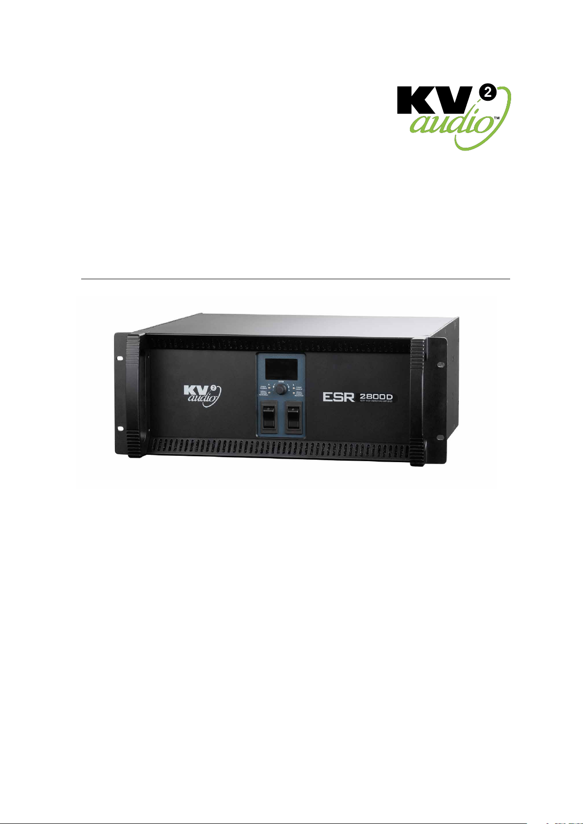
Important Safety Instructions
Before using your ESR2800D Amplier, be sure to carefully read the applicable items of these operating instructions
and the safety suggestions.
1. Read all product instructions.
2. Keep printed instructions, do not throw away.
3. Respect and rewiew all warnings.
4. Follow all instructions.
5. Do not use this unit near water, in unprotected out door areas or in rain or wet conditions.
6. Clean only with dry cloth.
7. Do not block any ventilation openings.
8. Install in accordance with KV2 Audio's recommended installation instructions.
9. Do not install near any heat sources such as heat radiators, heat registers, stoves or other apparatus that produce heat.
10. Do not defeat the safety purpose of the grounding type plug. A grounding type plug has two blades and a third
grounding connector. The third connector is provided for your safety. If the provided plug does not t into your outlet,
consult an electrician for replacement of the obsolete outlet.
11. Protect the power cord from being walked on or pinched, particularly at plugs, convenience receptacles.
The AC mains plug or appliance coupler shall remain readily accessible for operation.
12. Only use accessories specied by KV2 Audio.
13. Unplug this Amplier during lightning storms or when unused for long periods of time.
14. Refer all servicing to qualied service personnel. Servicing is required when the Amplier has been damaged in any
way, such as when the power-supply cord or plug has been damaged; liquid has been spilled or objects have fallen
into the Vents; rain or moisture has entered the Amplier; the Amplier has been dropped; or when for undetermined
reasons the Amplier does not operate normally.
15. Do not remove front or back panels. Removal of the panel will expose hazardous voltages.
There are no user serviceable parts inside and removable may void the warranty.
16. An experienced user shall always supervise this professional audio equipment.
CAUTION: TO REDUCE THE RISK OF ELECTRIC SHOCK, DO NOT REMOVE THE PANELS.
NO USER-SERVICEABLE PARTS INSIDE. REFER SERVICING TO QUALIFIED PERSONNEL.
WARNING: To prevent re or electric shock, do not expose this equipment to rain or moisture.
SAFETY SUMMARY
To reduce the risk of electric shock, disconnect the Amplier from the AC mains before installing audio cable.
Reconnect the power cord only after making all signal connections. Connect the Amplier to a two pole, three- wire
grounding mains receptacle. The receptacle must be connected to a fuse or circuit breaker. Connection to any other type
of receptacle poses a shock hazard and may violate local electrical codes. Do not allow water or any foreign object to get
inside the Amplier. Do not put objects containing liquid on or near the unit. To reduce the risk of overheating the Amplier,
avoid exposing it to direct sunlight. Do not install the unit near heat-emitting appliances, such as a room heater or stove.
This Amplier contains potentially hazardous voltages. Do not attempt to disassemble the unit. The unit contains no user
serviceable parts, repairs should be performed only by factory trained service personnel.