NeoDen K1830 User manual

NeoDen K1830
High Speed Pick and Place Machine
User Manual
Model:K1830 High Speed Pick and Place Machine
Version:V1.0
1
Zhejiang NeoDen Technology Co.,Ltd.

1. Equipment installation and precautions 1.1Machine Dimension.................................................................................... 4
1.2 Structure of Neoden K1830............................................................................................................................................5
1.3Working Area Structure................................................................................................................................................... 6
1.4 Important Notice.............................................................................................................................................................8
1.5 Operation flow chart.......................................................................................................................................................9
1.6 Flow chart of making a programming file................................................................................................................... 10
2.PCB Editing............................................................................................................................................................................. 11
.....................................................................................................................................................................................................11
2.1 PCB forward settings.................................................................................................................................................12
2.1.1 Mag Fixture....................................................................................................................................................... 12
2.2 PCB Eject setting..........................................................................................................................................................13
After click “Eject”no matter under Mag fixture or Rail mode,the thimble will go down in “track section 2”,”track
section 3”begin to work and PCB will feed to back conveyor.......................................................................................... 13
2.3 PCB Forward Position Setting..................................................................................................................................... 13
3.Panelized PCB Edit................................................................................................................................................................ 14
3.1 Panelized PCB origin (SMD1 coordinate).................................................................................................................14
3.1.1 Single board................................................................................................................................................ 14
3.1.3 Mirror board................................................................................................................................................... 16
3.2 PCB angle..................................................................................................................................................................... 18
4. Coordinate information.............................................................................................................................................. 18
4.1 PCB Mark setting...................................................................................................................................................... 18
(1)Panelized mark point................................................................................................................................... 18
(2)Single mark point........................................................................................................................................... 18
4.2 Mark point alignment................................................................................................................................................ 18
4.3 Mark Point information............................................................................................................................................. 19
图(2.1.3.2-6)..................................................................................................................................................................24
5.2 Feeder setting................................................................................................................................................................27
6.Nozzle Information..................................................................................................................................................................30
7. Assembly Interface................................................................................................................................................................. 30
8.System Setup........................................................................................................................................................................... 34
.....................................................................................................................................................................................................34
8.1 Feeder Position Config.................................................................................................................................................35
8.2 Component Positions Setup..........................................................................................................................................36
8.3 Basic Configuration......................................................................................................................................................39
DEAR USERS:
PLEASE READ THIS USER MANUAL COMPLETELY BEFORE
OPERATING. THIS UNIT AND RETAIN THIS BOOKLET
FOR FUTURE REFERENCE.
2
Zhejiang NeoDen Technology Co.,Ltd.

9. Manual Test.............................................................................................................................................................................41
10. First trial and test................................................................................................................................................................ 43
10.1 Program first dry run................................................................................................................................................ 43
10.2 First production test..................................................................................................................................................43
10.3 Component Inspection............................................................................................................................................43
10.4 Continuous SMT production................................................................................................................................... 44
11. Structure and maintenance instruction................................................................................................................................. 45
11.1 Feeder Brief Introduction...................................................................................................................................... 45
11.2Installing tape and reel components............................................................................................................................ 46
11.3Incorrect installation Samples:................................................................................................................................. 47
11.3.1Nozzle............................................................................................................................................................... 49
12. Maintenance..................................................................................................................................................................50
12.1 Take effective measures to reduce /avoid malfunction......................................................................................50
12.2 Maintenance....................................................................................................................................................... 51
12.3 Related issues during solder paste printing process..........................................................................................52
3
Zhejiang NeoDen Technology Co.,Ltd.

1. Equipment installation and precautions
1.1Machine Dimension
Figure 1- Machine dimension
4
Zhejiang NeoDen Technology Co.,Ltd.

1.2 Structure of Neoden K1830
Figure 2-Ports and Appearance
(3)
(9)
(1)
(2)
(4)
(5)
(6)
(7)
(10)
(11)
(12)
(1)Warning Light(Triple Color)
(2)Safety cover
(3)Front Feeder Slots 1-33(Reference value)
(4)Electric Feeder Port
(5)12 inch high-definition display
(6)Emergency Button
(8)
(7)USB port
(8)Pause button
(9)Mouse keyboard bracket
(10)Power Switch
(11)Air source input
(12)Heavy load pedestal
5
Zhejiang NeoDen Technology Co.,Ltd.

1.3Working Area Structure
Figure 3- Top view of main mounting area
6
Zhejiang NeoDen Technology Co.,Ltd.

Figure 4-X-axis Beam
Figure 5-Main Placement Head Camera
7
Zhejiang NeoDen Technology Co.,Ltd.

1.4 Important Notice
Figure 6-The air supply of the equipment shall not be less than0.6MP Figure 7- Feeder Pressure 0.55MP
Warning of failure risk of camera identification,please referring to Figure 3 and
Figure 5:The following parts are forbidden to touch and impact
Front IC Camera Back IC camera Left mark camera Right mark camera
Left mark camera light source Right mark camera light source
Warning of accuracy failure risk, refer to Figure 3: The following components are
prohibited from touching and impacting.
Return to zero column
For the risk of accuracy failure, refer to Figure4: When manually moving XY, it must
be carried out on the X-axis beam moving point;
Warning of electric shock, be sure to follow the requirements below:
Connect the input power supply that meets the requirements of the equipment, the
electrical interface of the machine to the ground must be effectively grounded;
Any time you enter the case and stick to the head for maintenance, you need to shut down
the machine properly and cut off the power supply;
Warning of equipment life reduction,be sure to follow the requirements below:
When installing the equipment, the equipment must be leveled;
Correct shutdown: shut down the operating software and the system before turning off
the main
p
ower switch;
8
Zhejiang NeoDen Technology Co.,Ltd.

1.5 Operation flow chart
NO. Flow chart Note
1
1. The pick and place machine is a precision equipment. In the
installation position of the machine, it is necessary to carry out horizontal
correction before and after the equipment to prevent the uneven operation
of the equipment from damaging the service life of the equipment;
2. Connect and fix the equipment interface before and after the
equipment, and connect and fix the ground wire;
3. The access power must meet the requirements of power identification;
4. No less than 0.6mp air source input and adjust the pressure value to
OK;
5. Check the safety of the working area of the mounting head;
6. The XY transmission parts are not fastened and interfered, and check
that the emergency stop switch is in normal state;
2Power on and turn the power switch clockwise;
3
1,1. When the self-test is carried out, the head indicator light of the
mounting head and the light source of the IC camera will be on and
flash briefly to indicate that the self-test is normal;
2,XY initialization (origin reset) is normal, the software enters the file
list interface, and no error report pops up;
4After power on, directly enter the file list page;
5See page 10 for the introduction of machine operation for
details;
6
Suggestions on production process:
1. First component confirmation: confirm the component angle
and polarity, component picking position and mounting
position;
2. Start production after confirming solder paste printing and
temperature setting;
7Production process;
8After the production is finished, reset the origin and prepare to
shut down;
9Shut down the system via computer, then power off the
machine.
10 Disconnect the electricity supply after the system being
powered off.
Software shut down
System shut down
Power OFF
Exit
Production Finished
Pre
p
aration
Power ON
Automatic Test
Power on
p
a
g
e
Program and Edit;
Production
Shutdown ste
p
s
Mountin
g
Modify
Abnormal
Start-u
p
ste
p
s
9
Zhejiang NeoDen Technology Co.,Ltd.

11 Keep the machine clean, daily maintenance of the nozzles
assures high utility.
1.6 Flow chart of making a programming file
Note:
A. The basic procedure of making a programming file by manual programming or import coordinate file is
similar, but there are two different parts: component list and fiducial setting.
B. Please find the detailed operation steps of the differences on relative page.
Start
Edit the file
Feeder settin
g
s
PCB feed settin
g
Fiducial settin
g
Component setup
PCB feedin
g
Penalized PCB first chip
Save and return
Select file and start
See P 12
See P 12
See P 14
See P 19
See P 18
See P 26
10
Zhejiang NeoDen Technology Co.,Ltd.

2.PCB Editing
File list introduction::
(1) Excel Open:The Excel table of the file can be modified directly in the table for some routine operations,
simplifying the programming operation.
(2) Edit: select a file and click Edit to enter the corresponding editing interface.
(3) Processing: after editing the file, after checking the correctness, select the file and click processing to mount.
(4) Export file: After connecting an U disk, select the file and click Export, after the successful notice pops up, the
export is finished.
(5) Import from U disk: for the files that have been edited offline, they can be directly imported from U disk for
mounting. After connecting U disk, click Import from U disk, select the corresponding files in the new window, and
click OK. When the imported files are showed in the file list, the operation is finished.
(6) Delete: select the corresponding file, click delete, a prompt window will pop up, and click Yes.
(7) Copy: select the corresponding file, click Copy, and the file list will generate a file of xxxcopy1. In order to
prevent misoperation, a new file can be copied before operation.
(8) Add a new file: click Add to open the input window, input the file name, and click OK. At this time, when the file
list interface displays new files, the operation is successful.
11
Zhejiang NeoDen Technology Co.,Ltd.

On the file list page, select an existing file or add a new file and name it, and then select the file for editing. The editing
page is shown as follows:
2.1 PCB forward settings
In manual programming, this item is the primary editing item, and the board entry setting is as shown in the figure:
2.1.1 Mag Fixture
Select tray to fix the board feeding mode, place the PCB to be installed in the proper position in the mounting area, and then
click "top plate control" to fix the PCB.
12
Zhejiang NeoDen Technology Co.,Ltd.

2.1.2 Tracks:
Select the “Tracks”on PCB Feed Setting interface:
Tracks width setting:Set correct PCB width value until the PCB can move smoothly
PCB Feed Test:Put PCB to “Tracks Section 1”,Click “forward”, PCB will move to “Tracks section 2” and stop at the
cylinder thimble position through the sensor,cylinder will raise the PCB, then thimble will go down, PCB feeding complete.
The adjustment method of the tracks width:Put the PCB on the front conveyor,feed the PCB to the tracks of pick and place
machine, gently push the PCB back and forth by hand to leave a tiny gap of about 1mm in the rail(add extra 1mm from PCB
width), click”Width set” and follow the prompt window to check whether meet the zero return condition. After zero return,
it will be adjusted to setted width.
2.1.3 Long Tracks:
Select the “Long Tracks”on PCB Feed Setting interface,then all track sections start work simultaneously.
Tracks width setting:Set correct PCB width value until the PCB can move smoothly
PCB Feed Test:The long tracks sends feed signal to the front conveyor, and feed PCB to cylinder thimble 1 position,
cylinder will raise the PCB,then thimble 1 will go down,PCB feeding phase 1 is completed.After above placement is
completed, the PCB in the waiting area is released, feed to cylinder thimble 2 position, cylinder will raise the PCB,then
thimble 2 will go down,PCB feeding phase 2 is completed.After above placement is completed, the PCB in the waiting area
is released, feed to cylinder thimble 3 position, cylinder will raise the PCB,then thimble 3 will go down,PCB feeding phase
3 is completed.
2.2 PCB Eject setting
After click “Eject”no matter under Mag fixture or Rail mode,the thimble will go down in “track section 2”,”track section
3”begin to work and PCB will feed to back conveyor
2.3 PCB Forward Position Setting
Need set the PCB forward position before click “forward”
Step:Click “Align”and enter the “align”interface,set the forward position according to the photo took by mark camera,and
select “align method-nozzle 1”,then click “save”to save the forward position information.
13
Zhejiang NeoDen Technology Co.,Ltd.
3.Panelized PCB Edit
3.1 Panelized PCB origin (SMD1 coordinate)
Function: This is mainly to determine the first component on single or panelized PCB of manual program or imported file.
The principle is to collect and calculate the data of each board’s relative spacing, in order to achieve the calculation of the
real coordinate.
Note: the panelized PCB origin (SMD1 coordinate) and panelized list setting of the manual program mode is the
same as file import mode.
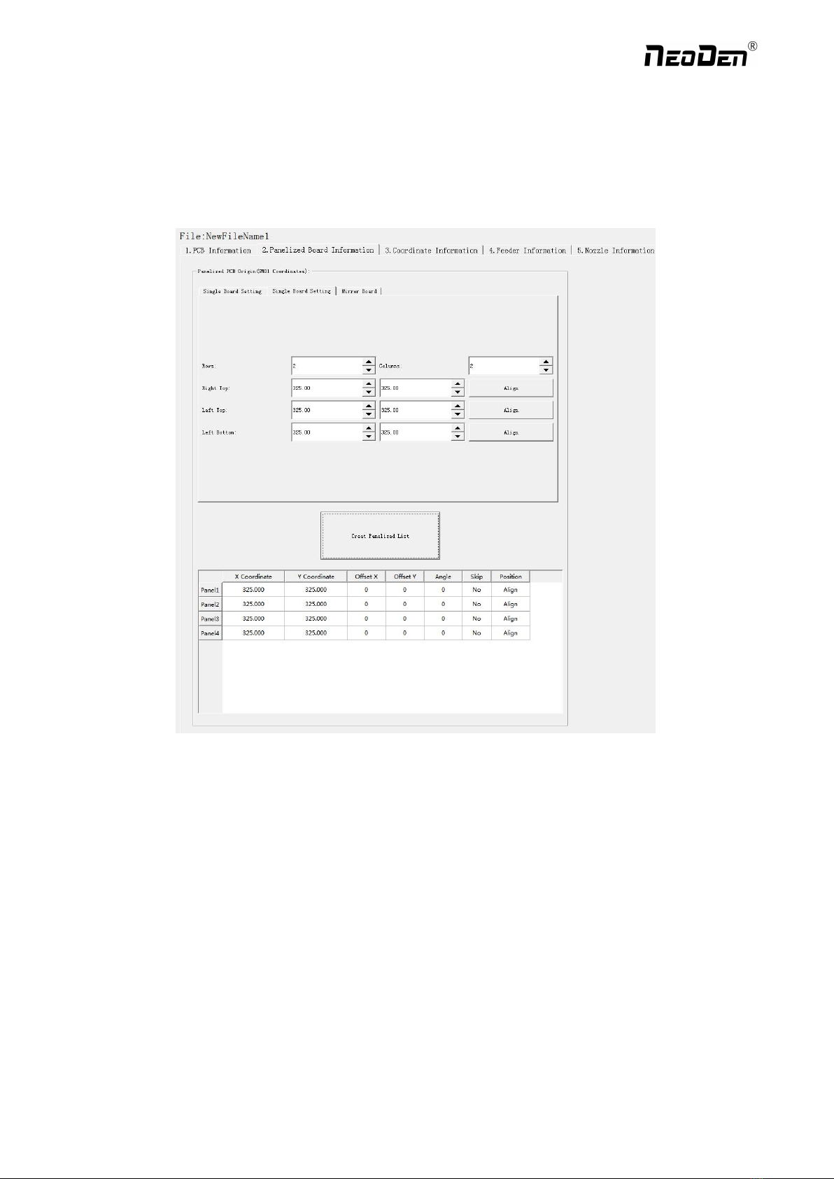
3.1.1 Single board
Click “single board setting”, you will see the “align” button of the SMD1 position that means the first component on the
component setup. Click “align” to enter the vision align interface, we need find the first component that on the component
list,generally we choose the center of the component, see figure
14
Zhejiang NeoDen Technology Co.,Ltd.

15
Click “ok”, it will back to the previous interface, click “create panelized list” button, the data which on the panelized list
will change.Can see the “SMD1 information”on the list and do double check via “align”button.
3.1.2 Panelized board
The steps of the panelized board programming are similar with the single board, but need pay some attention to several
points below
The row and column are determined by the positioning of PCB on working area. The direction along the rails is the column,
the direction perpendicular to the rail is row, then please enter data in the row and column.
Please refer to the data collecting method of each position information as following:
●The data of “left bottom” is collected according to first component in the component list of programming file. Press
“align” of left bottom, find the left bottom panel that is nearest to the left side and nearest to the feeding position, then find
the first component which on the chip list of this panel, align the center of this component. After saving the data, it will
return to the “PCB information” automatically.
Zhejiang NeoDen Technology Co.,Ltd.

●The data of “left top”: on the alignment interface, find the left top panel that is nearest to the left side but farthest to the
feeding position, then find the component same as the component that aligned on the “left bottom”, align the center of this
component. Click save and cancel, it will return to the “PCB information” automatically.
●The data of “right top”: on the alignment interface, find the right top panel that is nearest to the right side but farthest to
the feeding position, then find the same component as the component that aligned on the “left bottom”, align the center of
this component, click save and cancel, it will return to the “PCB information” automatically.
After setup, click “create panelized list”, the panelized list will be generated accordingly in the blank. You can also
double-confirm each position by clicking “Align”.
3.1.3 Mirror board
The steps of the Mirror board programming are similar with the Panelized board, but need pay some attention to several
points below
(1)Mirror board includes row panelized and column panelized
16
Zhejiang NeoDen Technology Co.,Ltd.

17
Row panelized: several same PCBs are arranged in horizontal direction, and the nearby rows are mirrored
Column panelized: several same PCBs are arranged in vertical direction, and the nearby columns are mirrored
(2)Panelized Board Row and Column
The row and column are determined by the positioning of PCB on working area. The direction along the rails is the column,
the direction perpendicular to the rail is row, then please enter data in the row and column.
(3)Please refer to the data collecting method of each position information as following:
After select the corresponding mirror board panelized method(column or row)and data of column&row,may occur the
situation of the align interface turn to gray and can’t be edited,then no need do position align.
Based on actual mirror board data,right side is showing corresponding images and can find the first component on it.
●The data of “right top”on original board: on the alignment interface, find the right top panel that is nearest to the right
side but farthest to the feeding position, then find the first component which on the chip list of this panel, align the center of
this component, click save and cancel, it will return to the “PCB information” automatically.
●The data of “left top”on original board: on the alignment interface,find the left top panel,then find the component same as
the component that aligned on the “right top”,align the center of this component, click save and cancel, it will return to the
“PCB information” automatically.
●The data of “left bottom”on original board:on the alignment interface,find the left bottom panel,then find the component
same as the component that aligned on the “right top”, align the center of this component. After saving the data, it will
return to the “PCB information” automatically.
●The data of “left bottom”on mirror board:on the alignment interface,find the left bottom panel,then find the component
same as the component that aligned on the “right top”, align the center of this component. After saving the data, it will
return to the “PCB information” automatically.
After setup, click “create panelized list”, the panelized list will be generated accordingly in the blank. You can also
double-confirm each position by clicking “Align”. Note:The angel difference between original and mirror board is 180
degree,original board is 0 degree,mirror is 180 degree.
Introduction of Align interface:See below fig.
Save and Back:After align the center of components,click “save and back”to save the date.
Close and Back:Refer to exit the current interface.
Alignment Method:Include left mark camera,nozzle 1-8,right mark camera,choose the alignment method according to
the actual situation,right side will show the real image by mark camera alignment.
Zhejiang NeoDen Technology Co.,Ltd.

Nozzle down test:If choose left or right mark camera alignment method,this function will turn to gray and not available
to operate.If choose nozzle1-8 alignment method,this function will be black and available to operate.Insert a pick height
value and then click “nozzle down test”to judge whether the setted pick height is reasonable or not.
Point 1,Point 2,Middle point :Use to confirm the IC center coordinate.For example,if choose alignment mthod”left
mark camera”,first select the first pitch center in left-bottom corner,click point 1,then select the second pitch center in
right-top,click point 2,finally click middle point,the machine can calculate out the IC center coordinate.
Light source:outer ring,middle ring,Inner ring,Mark point generally select to use outer or inner ring,select
corresponding light source according to PCB kind.
Brightness:Image recognize brightness can be adjusted on the drop-down list
3.2 PCB angle
PCB angle detect should be under the mode of Single board and manual programming,PCB angle will influence the
accuracy of mounting. The angle closer to 0 degree the better, and the angel deviation need to be within 1 degree. The angle
of PCB is generated according to panelized PCB coordinate, but we can also adjust the angle by manual. Click “Angle
Detect” button, according to the index of machine to choose two points, then a new PCB angle will be generated. (Note, the
two points need to be paralleled)
4. Coordinate information
4.1 PCB Mark setting
Function: After finishing mark setting, when the machine is working, the specific position and direction of PCB can confirm
via setting mark. Only in this way the next step of mounting work can carry out.PCB mark setting interface see below fig.
(1)Panelized mark point
It is mainly used for multiple identical PCB boards consistent of the whole board, when place every panel board, the
machine will rescan small panel board’s mark point.
(2)Single mark point
It is mainly used for a single PCB board and multiple identical PCB boards consistent of the whole board (Notice:
coordinate programming is done as a single board)
Generally, need to select 2 or 3 mark points.
4.2 Mark point alignment
Manual alignment:If there is no mark point on the PCB, which can through some location holes and set up some special
reference point manually to replace and confirm reference position. Note:Generally use SMD1 coordinate in chip list and
the one that is relatively easy to find far away from SMD1 as mark points,In this way, the relative placement effect will be
18
Zhejiang NeoDen Technology Co.,Ltd.

better during placement,the reference point is determined manually.
Auto alignment:The machine will scan and align mark points automatically.
4.3 Mark Point information
Mark point Coordinate:Import the coordinate automatically status: the data collection of mark point, which through PCB
circuit board to find mark point coordinate information directly, and input directly. Manual programming status:Select mark
point on the list and click “align”,enter the image capture page,and then find the center of the mark point via movement,
click "Mark align" see below figure, and then click "Save and Back" to go back to main page.
Min, max value: means the size of mark point, it has a floated value, which can prevent recognizing mark point wrongly.
Light source: Dividing into inner and outer, if select the hole as mark point which need to choose the inner of light source; If
select bright spot as fiducial which need to choose the outer of light source.
Brightness:The brightness when align the mark point,if select bright spot,generally set 20,can adjust according to actual
situation.
Range:If there are interference points near the Mark point, you can input a certain value and ensure identify the Mark point
more accurately.
Circle Degree:Input reasonable circle degree value,can avoid interference from other points effectively.
Mode:Dividing into white point and black point, select black point mode if have hole and bright point,select white point
mode if have bright point.
Camera:Support select left camera and right camera(user can select the camera for calibration according to the actual
situation),also can select default setting camera,the machine will use corresponding camera during work.
Except for the coordinate of Mark point, the settings of min,max, light source, brightness, range, circle degree, mode,
camera are same no matter automatically imported or manually imported.
Mark point add and delete: Click “new”to add the mark point,click “delete”to remove the selected mark point you want.
19
Zhejiang NeoDen Technology Co.,Ltd.

20
4.4 Component list setting
Function: display the information and mounting order of components. The components’ quantity and mounting information
can be added through manual programming or importing files , see below figure:
4.4.1 Manual programming
(1) Select manual programming;
(2) Edit the first component: there will be an example component in the component information list, modify the sample
component and click position “align”, the page will switch to the vision of up-looking camera automatically. Move the
camera and find the first component’s center coordinate. Click save.
(3) Fill in the information of component: Stack refers to which stack No. the component located; Nozzle refers to which
nozzle used to mounting the component; Specification refers to the component’s value; Footprint refers to the common
footprint name as 0402,0603,0805 etc; XY coordinate refers to the position of where the component is mounted, align the
center position of component, it will display synchronously; The angle is based on the placement direction of components
on the circuit board. Transverse is 0 degree or 180 degree, vertical is 90 degree or negative 90 degree, which mainly
depends on the polarity of component, degree must be integer degree; Skip setting includes true or false, false means keep
mounting, true means skip mounting this component. After finish all parameters’ editing, the setting of first component
information finish.
(4) Click ‘New’ to add one row on the component list. The information will exactly copy from the top row. Click align to
find the second component’s coordinate. Then click save to edit the other information such as name, value, footprint and
angle etc. Keep adding new component until the whole PCB finish. Please note the the stack and nozzle do not need to be
edited manually. It can be set through feeder setting interface with ‘Assign all sequentially’ button to assign the information
Zhejiang NeoDen Technology Co.,Ltd.
Table of contents
Other NeoDen Industrial Equipment manuals


Popular Industrial Equipment manuals by other brands

Belden
Belden Lumberg LioN-Link 0940 DSL 601 Technical manual

Siemens
Siemens Readme SIVArc manual

Siemens
Siemens 3VA960 0QB00 Series operating instructions

ABB
ABB HT842688 Operation manual

Trumpf
Trumpf TruHeat HF 1000 Series operating instructions

schmersal
schmersal AZM190 RK Series operating instructions


