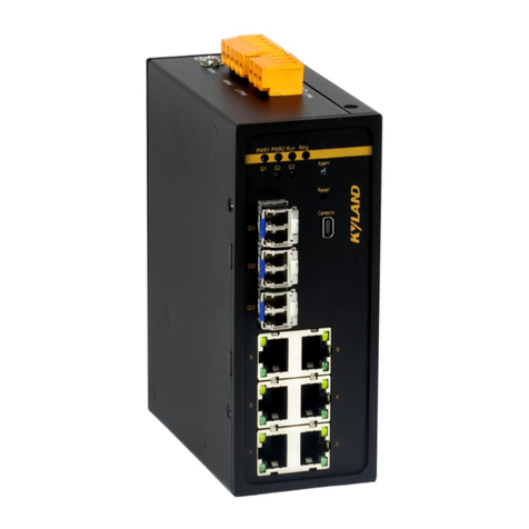
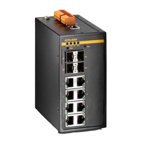
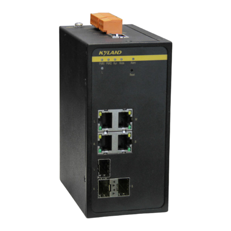
KYLAND KIEN6000T User manual

KIEN6000T Industrial Ethernet Switch
User’s Manual
KYLAND Telecom Technology Co., Ltd.

KIEN6000T Industrial Ethernet Switch
User’s Manual
Copyright © 2005 KYLAND Telecom Technology Co., Ltd.
All rights reserved.
No part of this documentation may be excerpted, reproduced, translated, annotated or
duplicated, in any form or by any means without the prior written permission of KYLAND
Corporation.
Publisher: KYLAND Telecom Technology CO., LTD
Address: 5/F, Office Building, Transport Center, East of Xisanqi Bridge
Haidian District, Beijing, China
Website: http://www.kyland.com.cn
Postcode: 100096
Tel: (+86 10)82900770
Fax: (+86 10)82900780
E-mail:marketing @ kyland. com. cn
Version: V1, Dec. 2005
No.: e6t02050701

Preface
KIEN6000T is a high-performance network-managed industrial Ethernet switch
specially designed by KYLAND Telecom Technology CO., LTD. for industrial
applications. Its high-performance switch engine, solid and closed case design,
high-efficient single-rib shape case heat dispersion surface without fans, overcurrent,
overvoltage and EMC protection at power input side, and excellent EMC protection of
RJ45 port allows KIEN6000T applicable in harsh and dangerous industrial
environments. The redundant function of optical fiber network, independent entire
network management channel, redundant power input function, and powerful entire
network real-time management system provides multiplex guarantee for reliable
operation of the system.
The User’s Manual for KIEN6000T Industrial Ethernet Switch mainly introduces the
information on technical principles, performance indexes, installation and
commissioning, network management etc. to provide users with references in startup,
expansion and routine maintenance. It is a practical teaching material that can be used
by users in trainings and helps the relevant technical personnel to increase their
knowledge and understanding of KIEN6000T industrial Ethernet switch.
This manual mainly includes the following contents:
Chapter 1 introduces general description and system features of KIEN6000T industrial
Ethernet switch;
Chapter 2 introduces performance indexes and service functions of KIEN6000T
industrial Ethernet switch;
Chapter 3 introduces hardware structure of KIEN6000T industrial Ethernet switch;
Chapter 4 introduces mounting process of KIEN6000T industrial Ethernet switch;
Chapter 5 introduces network management of KIEN6000T industrial Ethernet switch;
Chapter 6 introduces local management of KIEN6000T industrial Ethernet switch;
Chapter 7 introduces field test methods for KIEN6000T industrial Ethernet switch;
Chapter 8 introduces network-forming modes and system configuration of KIEN6000T

industrial Ethernet switch;
Appendix A introduces twisted pair and pin distribution rules of KIEN6000T industrial
Ethernet switch;
Appendix B introduces cable types and specifications of KIEN6000T industrial
Ethernet switch;
Appendix C introduces abbreviations used in this manful.
Statement: as product and technology upgrades and improves constantly, the
contents of this document may not completely accord with the actual
product. For product upgrading information, please access our company’s
website or directly contact with our company’s business representative.

Notice forSafety Operation
This product offers reliable performances as long as it is used within the designed
scope. Artificial damage or destruction of the equipment should be avoided.
Carefully read this manual and well preserve this manual for future reference;
Do not place the equipments near water sources or damp places;
Do not place anything on power cable which should be placed in unreachable
places;
Do not tie or wrap the cable to prevent fire.
Power connectors and connectors for other equipments should be firmly
interconnected and frequently checked.
In the following cases, please immediately disconnect the power supply and
contact with our company:
1. Water gets into the equipments;
2. Equipment damage or shell breakage;
3. Abnormal operation conditions of equipment or the demonstrated
performances have changed;
4. The equipment emits odor, smoke or noise.
Please keep optical fiber plugs and sockets clean. During operation of equipments,
do not stare directly into the cross section of optical fiber;
Please keep the equipment clean; if necessary, wipe the equipment with soft
cotton cloth;
Do not repair the equipment by yourself, unless it is clearly specified in the
manual.

Explanation of Warning Marks:
This manual uses two kinds of noticeable warning signs to arouse special attention
of users during operation. The implications of these signs are as follows:
Warning: pay special attention to the notes behind the mark,
improper operation will result in serious damage of the switch or
injury of operation personnel.
Caution, attention, warning, danger: remind the positions
requiring attention during operation.

-i-
Contents
Chapter 1 System Overview.........................................................................................................................1
1.1 Product Overview................................................................................................................................ 1
1.2 Packing list and unpacking check .......................................................................................................2
Chapter 2 Performance Indexes ..................................................................................................................5
2.1 System indexes .................................................................................................................................... 5
2.2 Service Interface.................................................................................................................................. 6
2.3 Service function................................................................................................................................... 6
Chapter 3 Hardware Structure....................................................................................................................9
3.1 System structure................................................................................................................................... 9
3.2 Switch Structure...................................................................................................................................9
3.2.1 Case ...........................................................................................................................................9
3.2.2 Front panel............................................................................................................................... 11
3.2.3 Top panel ................................................................................................................................. 14
3.2.4 Bottom panel............................................................................................................................ 18
Chapter 4 Hardware Mounting ................................................................................................................. 21
4.1 Mounting requirements......................................................................................................................21
4.2 Main unit mounting ...........................................................................................................................21
4.2.1 Rail mounting .......................................................................................................................... 21
4.2.2 Wall-mounting ......................................................................................................................... 23
4.3 Cable connection ............................................................................................................................... 26
4.4 Optical fiber connection ....................................................................................................................27
4.5 Cable wiring ...................................................................................................................................... 28
Chapter 5 Testing Method.......................................................................................................................... 31
5.1 Self-testing process............................................................................................................................31
5.2 Testing of Ethernet interface..............................................................................................................31
5.3 Testing of optical fiber interface........................................................................................................ 32
Chapter6 Networking Mode and System Configuration........................................................................ 33
-ii-
6.1 Networking mode...............................................................................................................................33
6.2 System configuration..........................................................................................................................35
AppendixA Twisted-pair and Pin Distribution......................................................................................37
Appendix B Cable Type and Specifications............................................................................................39
Appendix C Glossary...................................................................................................................................41

-1-
Chapter 1 System Overview
1.1 Product Overview
KIEN6000T is a high-performance managed industrial Ethernet switch specially
designed by KYLAND Telecom Technology CO., LTD. for industrial applications. Its
high-performance exchange engine, solid and closed case design, high-efficient
single-rib shape case heat dispersion surface without fans, overcurrent, overvoltage and
EMC protection at power input side, and excellent EMC protection of RJ45 port allows
KIEN6000T applicable in harsh and dangerous industrial environments. The redundant
function of optical fiber network, independent full network management channel,
redundant power input function, and powerful full network real-time management
system provides multiplex guarantee for reliable operation of the system.
KIEN6000T industrial Ethernet switch provides two mounting ways, DIN rail and
wall-mounting. On the front panel, there are two pairs of uplink redundant 100Base-FX
single mode or multi-mode optical fiber interfaces. The uplink optical fiber interfaces
can be used to form an optical fiber redundant ring network. In the event of system
failure, the recovery time of the redundant ring network should be less than 300ms. It
provides six 10Base-T/100Base-TX RJ45 ports. Each RJ45 port has adaptive function,
capable of automatically configuring to 10Base-T or 100Base-TX status and full
duplex or half duplex operation mode and automatically connecting MDI/MDI-X.
Features
High-performance Industrial Ethernet Switch
1. 10/100Base-T/TX Ethernet ports, adaptive, full/half duplex, auto MDI/MDI-X connection
2. 100Base-FX fiber ports, single mode/multimode, full duplex
3. High speed redundant ring with recovery time < 300ms
4. Supports VLAN to control broadcasting domain and segment flow.
5. Alarm relay output power supply and port link.
6. Broadcast storm control

KIEN6000T Industrial Ethernet Switch User’s Manual Kyland Telecom
-2-
Powerful Management Function
1. Integral management platform for the entire network based on RS232 standard. The management
system is immune against the attack of virus or hacker since the management channel is
independent to service channel.
2. Special-designed management software for upper PC realizes the auto-configuration of IP address
for networking devices and auto-scan/spanning of network topology.
3. Individual naming for each devices in the network.
4. Setting and query of VLAN.
5. Setting and query for alarm of power and ports link.
6. Setting and query for port working mode, prioritization, and rate
Industrial Power
1. Industrial power input of DC24V(DC18V~36V).
2. Reliable protection for EMC and against over-current/over-voltage.
3. Redundant power input.
Rugged Design
1. Ribbed heat-removal design (fanless); operation at -35℃to +75℃
2. Solid IP40 housing
3. Easy DIN-Rail mounting or optional wall-mounting
1.2 Packing list and unpacking check
1.Packing list
The packing case includes the following items:
KIEN6000T 1 unit
3-core DC power terminal 2 pieces
2-core alarming output terminal 1 piece

Kyland Telecom Chapter 1 System Overview
-3-
User’s Manual for KIEN6000T Industrial Ethernet Switch 1 copy
Customer Service Guideline 1 copy
Ф3 grounding cold pressed terminal, M3 ×
8 grounding screw
1 piece each
2.Unpacking check
Before opening the case, place it stably, pay attention to the direction of the packing
case, and ensure its right side is facing upward, so as to prevent KIEN6000T from
falling apart after opening the case. If a hard object is used to unclench the case, do
not overly extend the hard object into the case to avoid damage of the equipments
inside the case.
After opening the case, check the amount of KIEN6000T equipments (including
main unit of KIEN6000T, parts of equipment, user’s manual, customer service
guideline) according to the packing list, and check the appearance quality of
KIEN6000T.
Warning:
For the built-in precise parts of equipments, please handle with care and avoid
strenuous vibration to avoid affecting the performances of equipments.


-5-
Chapter2 Performance Indexes
2.1 System indexes
The system performance indexes of KIEN6000T industrial Ethernet switch are shown
in Table 2-1.
Table 2-1 System Indexes
System Indexes KIEN6000T
Quantity of RJ45 port 6 10Base-T/100Base-TX
Quantity of uplink redundant
fiber port 2 x 100Base-FX-SM/MM
System parameters
Supporting standard: IEEE802.3, IEEE 802.3x, IEEE 802.3u,
IEEE 802.1p, IEEE 802.1Q
Store-and-Forward speed: 148810 pps
Max. filtering speed: 148810 pps
Switching mode: Store-and-Forward
Switching bandwidth of system: 4.8G
Max. VLAN quantity: 16
Electromagnetic compatibility interference: :EN55022
Electromagnetic compatibility immunity: EN50082-2
Ethernet port
Physical port: shielded RJ-45
RJ-45 port: 10Base -T/100Base-TX, supporting automatic
negotiation function
Port standard: in line with IEEE802.3 standard
Transmission distance: <100m
Fiber port
Radiation power: >-13dbm(SM) >-20dbm(MM)
Receiving sensitivity: <-28dbm(SM) <-35dbm(MM)
Wave length: 1310nm(SM) 1550nm(SM) 1310 nm(MM)
Transmission distance: 20~80Km(SM) <2Km(MM)
Connector type: SC/FC
Transmission rate: 125Mbps
CONSOLE interface
Physical interface: shielded RJ-45
Interface standard: in line with RS232 standard (3 lines)
Interface speed: 19200bps
Power supply
Input voltage: double channelDC24V(DC 18V~36V)
Input power consumption: <6W
Overcurrent protection: built-in
Mechanical parameter Physical dimensions (heightwidthdepth): 142 ㎜55.4 ㎜

KIEN6000T Industrial Ethernet Switch User’s Manual Kyland Telecom
-6-
120.5 ㎜ ( excluding the dimensions of DIN rail and
wall-mounting components)
Mounting mode: DIN rail or wall-mounting
Heat removal method: Ribbed aluminum casing heat dissipation
without fan.
Outlet type: front outlet for service, top outlet for power supply
and network management
Shell protection: IP40
Weight: 1 ㎏
Ambient conditions
Operating temperature: -35℃~75℃
Storage temperature: -45℃~85℃
Humidity: 10%~95% (non-condensing)
2.2 Service Interface
1.Six 10Base-T/100Base-TX RJ45 ports. Each RJ45 port has self adaptation
function, capable of automatically configuring to 10Base-T or 100Base-TX state
and automatically working in full duplex or half duplex operation mode,
supporting automatic MDI/MDI-X connection. The transmission distance is less
than 100m.
2.Two pairs of uplink redundant 100Base-FX single mode or multi-mode optical
fiber interfaces. The maximum throughput of each pair of optical fiber interface is
100Mbps, and it is forced to work in 100M full duplex mode. They support optical
fiber line redundancy technology, with the redundancy switching time less than
300ms.
3.In line with/meeting IEEE802.3/802.3U/802.3X.
Meanings of RJ45 port indicator: yellow lamp – speed indicator; off: 10M
Green lamp – connection state indicator, on: effective connection of network; off:
no connection.
2.3 Service function
Configuration and Management
At KIEN6000T, the settings, queries and management can be realized for the whole switch or network

Kyland Telecom Chapter 2 Performance Indexes
-7-
system through CONSOLE interface.
LED Indicator
The LEDs indicate the port status correctly including transmission rate, link status and system status.
VLAN
The network can be divided into several VLANs according to ports, through which the users in one VLAN
can communicate each other. The VLAN of KIEN6000T conforms to IEEE802.1Q and can realize the
communication within one VLAN of different switches. KIEN6000T supports up to sixteen VLANs based
on IEEE802.1Q.
802.1p Prioritization
KIEN6000T conforms to 802.1p, which is used the most widely in LAN environment. The end-users of
KIEN6000T can make use of this function to configure the port-based prioritization when 802.1p is not
supported at user’s end and different priority is necessary for different ports’ services. Only the data
package without Prioritization in the Packet in the ports can be affected by this function. Each port of
KIEN6000T supports 2 levels (high, low) prioritization.
Layer-2 Switching
Switches work in two ways: Cut-Through and Store-and-Forward. In Cut-Through, a data packet is
immediately relayed further after detecting the target address; in Store-and-Forward, a data packet is
first read-in completely and checked for errors before the switch relays the same. KIEN6000T employs
Store-and-Forward that is a switching mode widely used.
Broadcast Storm Control
Broadcast storm is the ceaseless transfer of broadcast frame or multicast frame in bridge, which is
caused by loop and will waste much bandwidth. The purpose of broadcast storm control is to optimize
the performance of switch network. KIEN6000T supports the broadcast storm based on percentage.
With the control percentage, the broadcast flow of KIEN6000T will be monitored and controlled
effectively. The switch will filter out the over flow and ensure the flow percentage is normal once the
bandwidth of broadcast flow exceed the limit.
Alarming
KIEN6000T offers the alarming functions for power, port link and network. Through management
software, all the alarming functions can be configured functionally. The alarming information is shown
on management interface.
Setting for Working Mode of Port
KIEN6000T is able to set the working mode of all ports through management: full/half duplex,

KIEN6000T Industrial Ethernet Switch User’s Manual Kyland Telecom
-8-
auto-sensing, enforced full/half duplex, enforced 10M/100M etc.
Setting for Port Rate
KIEN6000T is able to set the rate of all ports through management as any integer
multiple of 32kbps.

-9-
Chapter3 Hardware Structure
3.1 System structure
The hardware structure of KIEN6000T industrial Ethernet switch is shown in Figure
3-1.
Figure 3-1 Hardware structure
The system hardware mainly consists of:
1.The switch controller uses high-performance ASIC chip technology, and provides
two-layer linear speed forwarding of data packet.
2.Optical fiber transceiver module is used for optical fiber interface, offering stable
performance.
3.Industrial power supply with overcurrent, overvoltage and EMC protection is
used as the power supply.
4.EMC protection is provided for all electrical interfaces and CONSOLE interface.
3.2 Switch Structure
3.2.1 Case
KIEN6000T case is a small DIN rail or wall mounting type structure. The entire unit
has a six-side-enclosed structure, with protection class up to IP40. The case’s left and

KIEN6000T Industrial Ethernet Switch User’s Manual Kyland Telecom
-10-
right side plates made of ribbed aluminum profile are a part of the heat dispersion
system of the entire unit. The single-rib structure can double heat dissipation area. The
heat generated when the unit is working is effectively dissipated into the environment
via the ribbed heat-dissipation surface in the form of radiation and convection greatly
increasing the high temperature resistance of equipment. Discarding the traditional
form of axial fan heat dispersion reduces power consumption of the entire unit and
increases the stability of the system. The figuration of KIEN6000T case is shown in
Figure 3-2.
Its contour dimension (excluding the dimensions of DIN rail and wall-mounting
components) is 142 ㎜55.4 ㎜120.5 ㎜(height×width×thickness)

Kyland Telecom Chapter 3 Hardware Structure
-11-
Figure 3-2 Outline drawing of KIEN6000T
Warning:
The shell of this switch is a part of the heat dissipation system of the unit. It may get
hot during working, so never touch the shell when the equipment is working to avoid
burning.
3.2.2 Front panel
The front panel of KIEN6000T industrial Ethernet switch has integrated two pairs of
optical fiber interfaces, six 10Base-T/100Base-TX RJ45 Ethernet ports and six system
and port operation indicators. Its structure is shown in Figure 3-3:

KIEN6000T Industrial Ethernet Switch User’s Manual Kyland Telecom
-12-
POWER2
I ndi cat or f or
Syst emOperat i ng
St at us
I ndi cat or f or
Port Speed
I ndi cat or f or Port
Connect i on St at us
Figure 3-3 Front panel diagram
Optical fiber interface
KIEN6000T has two pairs of redundant 100Base-FX full duplex single mode or
multi-mode optical fiber interface, with port number of 4 and 8 and SC or FC
connector. Optical fiber interface should be used in pairs (TX and RX are a pair),
TX interface is the transmitting end connected to the receiving end RX of the
optical fiber interface of another remote switch; RX is the receiving end
connected to the transmitting end TX of the same optical fiber interface of the
same remote switch. Two pairs of redundant 100Base-FX optical fiber interface
can be used to form an optical fiber redundant ring network. In the event of the
system fault, the recovery time of the redundant ring network is less than 300ms,
Table of contents
Other KYLAND Switch manuals

KYLAND
KYLAND Aquam5G Series Assembly instructions

KYLAND
KYLAND SICOM3008GV Series Assembly instructions

KYLAND
KYLAND KIEN1008BA Series Assembly instructions

KYLAND
KYLAND Aquam5 Series Assembly instructions

KYLAND
KYLAND SICOM6432G Series Assembly instructions

KYLAND
KYLAND SICOM3000S Assembly instructions

KYLAND
KYLAND Aquam8112 Series Assembly instructions

KYLAND
KYLAND SICOM3024P Assembly instructions

KYLAND
KYLAND SICOM6448G Series Assembly instructions

KYLAND
KYLAND SICOM3000A-LITE Assembly instructions