KYOKUTOH KIKK-EL User manual

・
Table of contents
・
Safety precautions
・
Parts name of KIKK-EL
・
Preparation
・
Maintenance
・
Technical data
・
Troubleshooting
・ Accessory & consumable
・ How to order
・ Contacts
Tip Changer
Tip ChangerTip Changer
Tip Changer(
((
(KIKK
KIKKKIKK
KIKK-
--
-EL
ELEL
EL)
))
)
User`s Manual
User`s ManualUser`s Manual
User`s Manual
Please read this manual before using KYOKUTOH`s Tip changer (KIKK-EL).
First Edition 2013/10/16
Revised Edition 2015/05/08
KYOKUTOH CO., LTD
KYOKUTOH CO., LTDKYOKUTOH CO., LTD
KYOKUTOH CO., LTD
1 ページ

2 ページ

1.0 Safety precautions 3
2.0 Parts name of KIKK-EL 5
3.0 Preparation
3.1 Installation 6
3.2 Dimention 7
3.3 Tip Position for setting and removing 8
3.4 Teaching for tip setting and removing 8
4.0 Maintenence
9
4.2 Procedure for charging a cap tip 10
4.3 Procedure for changing remover unit 11
4.4 Procedure for changing the cylinder 12
4.5 Procedure for changing the spring 12
5.0 Technical data
5.1 Types of magazines 13
5.2 Types of nails 13
5.3 Available cap tips 14
5.4 Parts list 15
6.0 Troubleshooting 16
7.0 Accessories & Consumption parts list
7.1 Consumption parts list 17
7.2 Limit switch/Proximity sensor 17
8.0 How to order 18
9.0 Contacts 19
4.1 Procedure for changing the magazine
Contents
ContentsContents
Contents
3 ページ

Abusolutely never disassemble or reconfigure this machine.
Abusolutely never disassemble or reconfigure this machine.Abusolutely never disassemble or reconfigure this machine.
Abusolutely never disassemble or reconfigure this machine.
This could result in malfunction, ignition or injury.
Do not put this unit in liquid or spill too much liquid
Do not put this unit in liquid or spill too much liquidDo not put this unit in liquid or spill too much liquid
Do not put this unit in liquid or spill too much liquid
(
( (
(over
over over
over 70㎖/
70㎖/70㎖/
70㎖/min, longer than 10 min) such as water.
min, longer than 10 min) such as water. min, longer than 10 min) such as water.
min, longer than 10 min) such as water.
This could result in malfunction.
Stop air supply before machine teaching.
Stop air supply before machine teaching.Stop air supply before machine teaching.
Stop air supply before machine teaching.
Manual tip inserting cause injury.
Do not put anything in tip container other than cap tips.
Do not put anything in tip container other than cap tips. Do not put anything in tip container other than cap tips.
Do not put anything in tip container other than cap tips.
Incorrect goods could result in malfunction and injury.
Prohibitions
ProhibitionsProhibitions
Prohibitions
1.0
1.01.0
1.0 Safety precautions
Safety precautionsSafety precautions
Safety precautions
This Tip Changer, KIKK-EL serise is designed to exchange damaged electrodes (hereinafter called tips) for new
tips in car production line. lease do not use for any purpose other than described in this manual. We are not be
able to take a responsibliliy for any damage or injury caused by results other than specified in this manual.
Wrong usage of this products could resault in death or serious injury of the operator.
Warning
WarningWarning
Warning
Wrong usage of this product could result in injury or physical damage to equipment.
Caution
CautionCaution
Caution
This symbol indicates operation that should not be done.
This symbol indicates operation that should be done.
Handling precautions
Handling precautionsHandling precautions
Handling precautions
4 ページ

Do not use rotation direction beside set.
Do not use rotation direction beside set.Do not use rotation direction beside set.
Do not use rotation direction beside set.
This could result in malfunction or injury.
Damaged pipe could result in malfunction.
Do not insert metallic articles such as a pins or needles in rotating part
Do not insert metallic articles such as a pins or needles in rotating part Do not insert metallic articles such as a pins or needles in rotating part
Do not insert metallic articles such as a pins or needles in rotating part
or opening part during operation.
or opening part during operation. or opening part during operation.
or opening part during operation.
This could result in operation malfunction or electrical shock.
Do not tilt this machine more than 45 degree when installing or operating.
Do not tilt this machine more than 45 degree when installing or operating.Do not tilt this machine more than 45 degree when installing or operating.
Do not tilt this machine more than 45 degree when installing or operating.
machine
machinemachine
machine
This could result in operation malfunction and injury.
This will generate poisonous gas.
Do not put undersigned tips in magazine.
Do not put undersigned tips in magazine.Do not put undersigned tips in magazine.
Do not put undersigned tips in magazine.
Incorrect tips type will cause malfunction and damage.
Stop air supply before exchanging sylinder, spring or nails
Stop air supply before exchanging sylinder, spring or nailsStop air supply before exchanging sylinder, spring or nails
Stop air supply before exchanging sylinder, spring or nails
or removing this unit.
or removing this unit. or removing this unit.
or removing this unit.
This could result in serious injury.
Firmly fix this unit to stand.
Firmly fix this unit to stand. Firmly fix this unit to stand.
Firmly fix this unit to stand.
Unstable installation causes imbalance tip setting or accident.
Remove alcohol or thinner properly after maintenance.
Remove alcohol or thinner properly after maintenance.Remove alcohol or thinner properly after maintenance.
Remove alcohol or thinner properly after maintenance.
The flying sparks can cause fires or explosions.
Protect air pipe from spatter.
Protect air pipe from spatter.Protect air pipe from spatter.
Protect air pipe from spatter.
The flying spatter causes air leak due to melting pipe.
Remove spatter which covers tip remover periodically.
Remove spatter which covers tip remover periodically.Remove spatter which covers tip remover periodically.
Remove spatter which covers tip remover periodically.
Spatter build-up can cause operation malfanction.
Cautions
CautionsCautions
Cautions
Prohibitions
ProhibitionsProhibitions
Prohibitions
Be sure to protect air pipe from any kinds of damages.
Be sure to protect air pipe from any kinds of damages. Be sure to protect air pipe from any kinds of damages.
Be sure to protect air pipe from any kinds of damages.
Keep hands away from opening part during operation.
Keep hands away from opening part during operation.Keep hands away from opening part during operation.
Keep hands away from opening part during operation.
This result in injury.
Do not use acidic or chlorine detergents for maintenance.
Do not use acidic or chlorine detergents for maintenance.Do not use acidic or chlorine detergents for maintenance.
Do not use acidic or chlorine detergents for maintenance.
※Be sure this guide reaches the operator.
5 ページ

No
1
2
3
4
Lower magazine MG****MR-L
Sensor pac(Option) KIKK-EL-SE-Pac
Name Model
KIKK-EL Body KIKK-EL**
Upper magazine MG****MR-U
Parts list
2.0
2.02.0
2.0 P
PP
Parts name
arts namearts name
arts name
①
②
③
④
④
④
6 ページ

7 ページ

3.1 How to install
3.1 How to install3.1 How to install
3.1 How to install
1. Install this machine in the area where welding robot can reach.
(Please refer to the following drawing for the dimention of the installation plate.)
2.Firmly fix tip changer with four M8 cap bolts (The stand must be solid and fixed)
3. Set the air filter to the air supply circuit.
4. Connect air cylinder to air hose, and place the spatter collecting case ahead.
(Hose and hose band can be included as options.)
5. Connect to the air supply.
Specification
Model KIKK-EL
Outer dimention 506W×296D×86H
Air pressure 0.5Mpa~
Weight 11kg
Mounting hole H70 × V58 (M8×4)
Mounting area H106× V78mm
Remover thickness & depth T31 × D49mm
Tip opening:Over 35mm
Throat depth: Over 25mm
Magazine
Remover
Use condition(Standard type)
Tip opening:Over 35mm
Throat depth : Over 50mm
Thrust about 1560N
Cylinder model CDQ2B-63-75DCM-M9BA
3.0
3.03.0
3.0 Preparation
PreparationPreparation
Preparation
8 ページ

3.2 Dimention
3.2 Dimention3.2 Dimention
3.2 Dimention
9 ページ

3.3 Tip Position for setting and removing
3.3 Tip Position for setting and removing3.3 Tip Position for setting and removing
3.3 Tip Position for setting and removing
3.4 Teaching for tip setting and removing
3.4 Teaching for tip setting and removing3.4 Teaching for tip setting and removing
3.4 Teaching for tip setting and removing
Preparations and precautions before operation
Preparations and precautions before operationPreparations and precautions before operation
Preparations and precautions before operation
1.Cut off the air supply when inserting or removeing tips by manual during test-driving.
2. Make sure that the machine is fixed on stand tightly.
3. Confirm the shank is joined tightly to the gun arm.
4. Check cap tips can be matched with the inside diameter of the removing part, the magazine inside diameter and the depth.
5. Confirm the connection of the air supply.
6.Check air cylinder operation and chucking rotation movement. (Test driving also possible)
7.Charge the cap tip which fits to the magazine.
8.Remove the cap tip from the magazine manually and confirm that next captip comes to the fixed position.
Operatation
OperatationOperatation
Operatation (Removing)
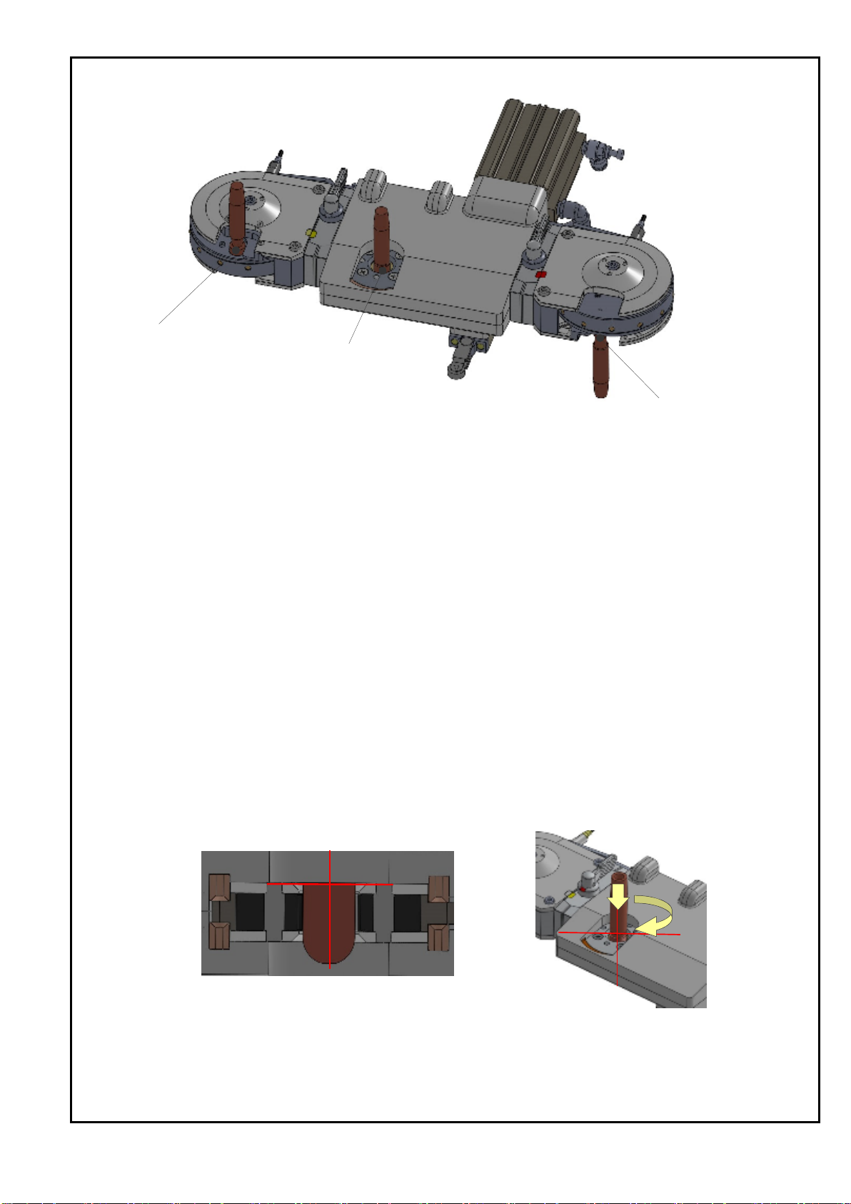
1.Position cap tips to the center of the removing part by teaching robot.
2.Confirm the center position of removing and move to the Z axial direction(up or down). ※Be careful about collision.
3. Memorize the location where the cap tip has almost entered in the remover.
4.Operate cylinder.(=The remover starts roatating)
5. 0.5 seconds after beginning of cylinder operation, move a robot back in the Z axial direction, 3mm.
*
**
*Please do the below action, since the cap tip can NOT be removed by only the rotation of the remover.
Please do the below action, since the cap tip can NOT be removed by only the rotation of the remover. Please do the below action, since the cap tip can NOT be removed by only the rotation of the remover.
Please do the below action, since the cap tip can NOT be removed by only the rotation of the remover.
(Upper→Raise about 3mm, Lower→Lower about 3mm)
(Upper→Raise about 3mm, Lower→Lower about 3mm) (Upper→Raise about 3mm, Lower→Lower about 3mm)
(Upper→Raise about 3mm, Lower→Lower about 3mm)
This action also prevents the robot gun and the KIKK from being damaged.
This action also prevents the robot gun and the KIKK from being damaged. This action also prevents the robot gun and the KIKK from being damaged.
This action also prevents the robot gun and the KIKK from being damaged.
The position of the cylinder switch needs to be re-adjusted when confirming the operation of the KIKK.
The position of the cylinder switch needs to be re-adjusted when confirming the operation of the KIKK. The position of the cylinder switch needs to be re-adjusted when confirming the operation of the KIKK.
The position of the cylinder switch needs to be re-adjusted when confirming the operation of the KIKK.
6.After the cap tip has removed from the shank, please return the cylinder.
7. Check the captip fell off
Tips for operation
Tips for operationTips for operation
Tips for operation
1.Movement timing of Z axial direction can be changed depending on the operation speed of the cylinder.
※Tip will not be removed when operation above has not been done.
*From the cylinder operation start to finsh, please adjust the time to approx. 1.5sec.
*From the cylinder operation start to finsh, please adjust the time to approx. 1.5sec.*From the cylinder operation start to finsh, please adjust the time to approx. 1.5sec.
*From the cylinder operation start to finsh, please adjust the time to approx. 1.5sec.
(It can be adjusted by using the speed controller on the cylinder)
(It can be adjusted by using the speed controller on the cylinder) (It can be adjusted by using the speed controller on the cylinder)
(It can be adjusted by using the speed controller on the cylinder)
2.For short length of cap tips, confirm the part of tip body to decide the inserting postiotion.
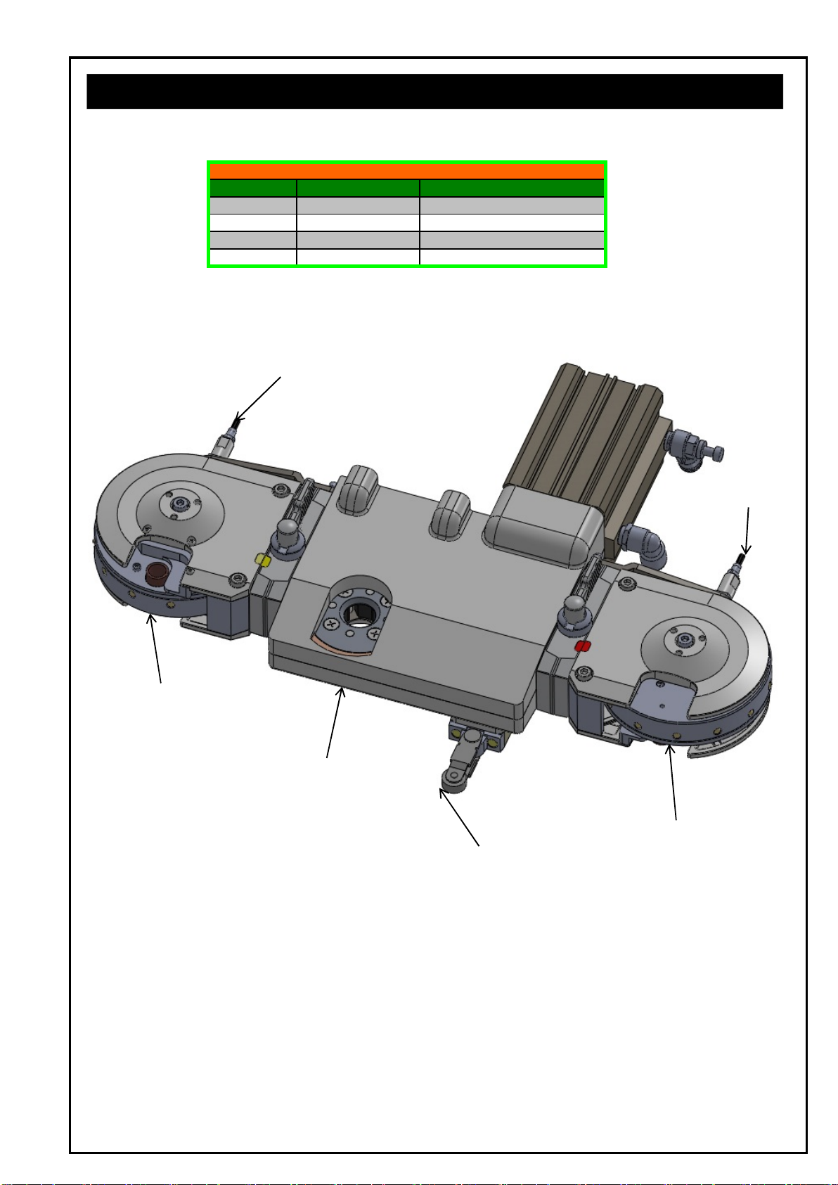
Upper tip setting part
Lower tip setting part
Tip removing part
10 ページ

The point of maintenance
The point of maintenanceThe point of maintenance
The point of maintenance
1. Confirm whether the machine is fixed on the stand tightly.
2. Check air pipe condition.
3. Remove spatter which is stuck with the remover.
4. Make sure that the magazine is fixed to the adapter tightly.
4.1 Procedure for changing the magazine
4.1 Procedure for changing the magazine4.1 Procedure for changing the magazine
4.1 Procedure for changing the magazine
1. Cut off the air supply.
2. Set the Purge dial to [UNLOCK].
3. Pull a magazine out from magazine adapter by both hands.
(Please Not to damage the proximity sensor)
4. Please put a spare magazine into the magazine adapter
5. Set the Purge dial to [LOCK].
6. Confirm the magazine is fixed tightly.
7. Check the signal of the proximity sensor(option) if purchesed.
4.0
4.04.0
4.0 Maintenance
MaintenanceMaintenance
Maintenance
Set the purge dial to UNLOCK ull the magazine out from
ush a spare magazine into adapter
and turn purge dial left to LOCK
11 ページ

4.2 Procedure for charging a cap tip
4.2 Procedure for charging a cap tip4.2 Procedure for charging a cap tip
4.2 Procedure for charging a cap tip
1. Cut off the air supply 2. Set the purge dial to UNLOCK
4. Set the cap tip one by one. (Be careful about direction of the cap tips) 3. Pull the magazine with both hands.
5. Push magazine into the adapter with both hands. 6. Set the purge dial to LOCK
12 ページ

4.3 Procedure for changing remover unit
4.3 Procedure for changing remover unit4.3 Procedure for changing remover unit
4.3 Procedure for changing remover unit
1. Cut off the air supply and remove the Upper body. (M6 x 7pcs)
2. Remove the arm ring plate and the remove shaft from the remover unit.
3. Take off the remover unit.
※The remover unit will be taken off as the picture below.
4. Do 1 to 3 in reverse order to exchange new one.
5. Check the operation of the remover unit by test-driving.
【Nails changing】
1. Remove seven M6 bolts of upper cover, and lift the upper cover of the remover unit.
2. Remove each nail fixed to lower cover.
3. Do 1 and 2 in reverse order with new nails.
4. Check the nails direction properly..
Center arm
Remover unit upper cover
Please assemble the nails
Please assemble the nails Please assemble the nails
Please assemble the nails
with lazer printed side up
with lazer printed side upwith lazer printed side up
with lazer printed side up.
countersunk screw(M6X4)
Cap bolts (M6x7)
Arm ring plate
Remover unit
Remove shaft
Nails
13 ページ

4.4 Procedure for changing the cylinder
4.4 Procedure for changing the cylinder4.4 Procedure for changing the cylinder
4.4 Procedure for changing the cylinder
1. Cut off air supply and remove a Upper Body. (7pc of M6 screws)
2. Take air-pipework out.
3. Remove the remove shaft and the arm ring plates. (refer to the picture below).
4. Please turn a knuckle joint counterclockwise and remove from a cylinder rod.
5. Please remove the volts(M8x4) from rear of the cylinder .
6. Cylinder exchange is completed in reverse order 1 to 5.
※Please do not put hands in removing part
4.5 Procedure for changing the spring
4.5 Procedure for changing the spring4.5 Procedure for changing the spring
4.5 Procedure for changing the spring
1. Cut off the air supply and remove the Upper Body. (7pc of M6 screws)
2. Hold up remover unit (Please refer to 4.3)
3. Separate remover unit while bringing up the spring and spring guide A.
4. Take spring guide B out to exchange the sprng inside with new one.
5. Spring exchange is completed in reverse order 1 to 4.
Spring
Remover unit
Spring guide A
Spring guide B
Cylinder fixing bolt(M8)
Knuckle joint
Arm ring plate
Knuckle joint
Remove shaft
14 ページ

5.1 Types of magazines
5.1 Types of magazines5.1 Types of magazines
5.1 Types of magazines
Magazine for upper tip
NO Cap tip dia Length of Tip
1 18mm~21mm
2 18mm~21mm
3 20mm~23mm
4 20mm~23mm
5 22mm~25mm
6 22mm~25mm
7 18mm~21mm
8 18mm~21mm
7 22mm~25mm
8 22mm~25mm
9 18mm~21mm
10 18mm~21mm
11 22mm~25mm
12 22mm~25mm
※We strongly recommend to have a spare magazine for upper and lower tips.
5.2 Type of nails (4nails in 1set)
5.2 Type of nails (4nails in 1set)5.2 Type of nails (4nails in 1set)
5.2 Type of nails (4nails in 1set)
1
Nail (for φ16tip)
Φ16 16
2
Nail (for φ19tip)
Φ19 19
3
Nail (for φ20tip)
Φ20 20
※We strongly recommend to have a spare magazine for upper and lower tips.
Model External dia.
of Captip PrintingNo. Type
Φ16
Φ19
Φ20
KIKK-EL16-P-001-16
KIKK-EL19-P-001-19
KIKK-EL20-P-001-20
Revolving nail
MG201821MR-L
MG201821MR-LMG201821MR-L
MG201821MR-L Lower Tip
MG202225MR-U
MG202225MR-UMG202225MR-U
MG202225MR-U Upper Tip
MG202225MR-L
MG202225MR-LMG202225MR-L
MG202225MR-L Lower Tip
MG192225MR-U
MG192225MR-UMG192225MR-U
MG192225MR-U Upper Tip
MG192225MR-L
MG192225MR-LMG192225MR-L
MG192225MR-L Lower Tip
MG201821MR-U
MG201821MR-UMG201821MR-U
MG201821MR-U Upper Tip
MG191821MR-U
MG191821MR-UMG191821MR-U
MG191821MR-U Upper Tip
MG191821MR-L
MG191821MR-LMG191821MR-L
MG191821MR-L Lower Tip
MG162225MR-U
MG162225MR-UMG162225MR-U
MG162225MR-U Upper Tip
MG162225MR-L
MG162225MR-LMG162225MR-L
MG162225MR-L Lower Tip
MG161821MR-L
MG161821MR-LMG161821MR-L
MG161821MR-L Lower Tip
MG162023MR-U
MG162023MR-UMG162023MR-U
MG162023MR-U Upper Tip
MG162023MR-L
MG162023MR-LMG162023MR-L
MG162023MR-L Lower Tip
Magazine
Model Upper/Lower
MG161821MR-U
MG161821MR-UMG161821MR-U
MG161821MR-U Upper Tip
5.0 Technical data
5.0 Technical data5.0 Technical data
5.0 Technical data
Nail
15 ページ

5.3 Available cap tip
5.3 Available cap tip5.3 Available cap tip
5.3 Available cap tip
Tip changer, KIKK-EL is designed in order to correspond to popular types of cap tips which
meet the following condition.
·External diameter - Φ16 ~Φ20
·Length - 16mm ~ 25mm。
·Shape of tip - Symmetry cap tip shape(Eccentric cap tip is no available)
(mm)
CuCr
ZrCuCr
Parallel part C dimenstion(more than 10mm)
Necessary dimension(mm) Material
External diameter(AΦ) Φ16~Φ20
Length(L) 16 ~25
Tip exchanging criteria
A
L
C
16 ページ

5.4 Parts list
5.4 Parts list5.4 Parts list
5.4 Parts list
(
KIKK-EL
)
No Name
1
Cylinder
2
Upper Body
3
Lower Body
5
Upper magazine
6
Lower magazine
7
Sensor pac(Option)
8
Spring
Remover unit
CDQ2B-63-75DCM-M9BA
4
MG****MR-U
MG****MR-L
KIKK-EL-SE-Pac
51-22100
KIKK-EL20-P-013-DC
KIKK-EL20-P-014-DC
KIKK-EL-ReU-TYPE-16(for φ16)
KIKK-EL-ReU-TYPE-19(for φ19)
KIKK-EL-ReU-TYPE-20(for φ20)
Parts list
Model
【5】Upper magazine
【1】Cylinder
【2】 Upper Body
【3】Lower Body
【6】Lower magazine
【4】Remover unit
【7】Sensor pac
【8】Spring
【7】Sensor pac
【7】Sensor pac
17 ページ

Trouble Cause Measure
1.Air is not supplied. Check the air pressure and fix it.
2.Breakdown of a cylinder. Check the air cylinder and exchange
A tip is not removed 3.Breakdown of a remover unit
4.Air pressure is not enough. Check the air pressure and adjust it.
(Recommended:0.5MPa)
1.Air is not supplied. Check the air pressure and fix it.
2.Breakdown of a cylinder.
Air cylinder does not work
3.Air pressure is not enough. Check the air pressure and adjust it.
(Recommended:0.5MPa)
1.A cylinder is not returned.
2.Air is not supplied. Check and adjust air pressure.
Removed tip does not fall down (Recommended:0.5MPa)
4.Remover nails not match a chip. Check the cap tip size and use proper tips.
Switch up and down or right and left side
of magazines .
Clean up adapter pins
Set to [UNLOCK]
4.Proximity sensor touches a magazine.
1.Purge dial is not set to [Unlock] Set to [UNLOCK]
Clean up the socket.
Check the tip size and change for
right size.
1.A spring in the magazine breaks. Exchange the spring.
2.Tip in different size is mixed. Get rid of wrong size tip.
1.Proximity sensor is broken. Eexchange the proximity sensor.
2.Proximity sensor is in wrong position.
A magazine does not fit into adapter or
it cannot be fixed.
The next tip in magazine does not come
to proper positon.
Adjust the position of proximity sensor.
Unable to confirm tip remains.
A magazine is not separated from
adapter.
1.Tip outer diameter is bigger than the
magazine inside.
1. Wrong orientation magazine or opposite
side of tip magazine.
2.Trash or dast can be jammed in adapter
side of magazine.
2.An adapter pin socket is filled with
trash.
3.Purge dail is set to [Lock]
Tip does not fit in magazine
2.Full of tips in the magazine.
Adjust the position of proximity sensor.
Trouble & Measure
for new one if necessary.
Check the air cylinder and exchange
for new one if necessary.
3.A remover nail is broken off. Check the nails of remover unit
and change it for new one.
Check the nails and exchange for new one if
necessaryand change it for new one.
Check the operation of a cylinder
and adjust it.
6.0 Troubleshooting
18 ページ

7.1 Consumption parts list
7.1 Consumption parts list7.1 Consumption parts list
7.1 Consumption parts list
・
・・
・Remover unit
Remover unitRemover unit
Remover unit
KIKK-EL-ReU-TYPE-16(for Φ16)
KIKK-EL-ReU-TYPE-16(for Φ16)KIKK-EL-ReU-TYPE-16(for Φ16)
KIKK-EL-ReU-TYPE-16(for Φ16)
KIKK-EL-ReU-TYPE-19(for Φ19)
KIKK-EL-ReU-TYPE-19(for Φ19)KIKK-EL-ReU-TYPE-19(for Φ19)
KIKK-EL-ReU-TYPE-19(for Φ19)
KIKK-EL-ReU-TYPE-20(for Φ20)
KIKK-EL-ReU-TYPE-20(for Φ20)KIKK-EL-ReU-TYPE-20(for Φ20)
KIKK-EL-ReU-TYPE-20(for Φ20)
・
・・
・Magazine
MagazineMagazine
Magazine
7.1 Sensor pac(Option)
7.1 Sensor pac(Option)7.1 Sensor pac(Option)
7.1 Sensor pac(Option)
・Sensor pac
・Sensor pac・Sensor pac
・Sensor pac
51-22100
51-2210051-22100
51-22100
KIKK-EL-SE-Pac
KIKK-EL-SE-PacKIKK-EL-SE-Pac
KIKK-EL-SE-Pac
MG202225MR-L
MG202225MR-LMG202225MR-L
MG202225MR-L
MG191821MR-L
MG191821MR-LMG191821MR-L
MG191821MR-L
MG192225MR-U
MG192225MR-UMG192225MR-U
MG192225MR-U
MG192225MR-L
MG192225MR-LMG192225MR-L
MG192225MR-L
MG201821MR-U
MG201821MR-UMG201821MR-U
MG201821MR-U
MG201821MR-L
MG201821MR-LMG201821MR-L
MG201821MR-L
MG202225MR-U
MG202225MR-UMG202225MR-U
MG202225MR-U
MG161821MR-U
MG161821MR-UMG161821MR-U
MG161821MR-U
MG162023MR-U
MG162023MR-UMG162023MR-U
MG162023MR-U
MG162023MR-L
MG162023MR-LMG162023MR-L
MG162023MR-L
MG162225MR-U
MG162225MR-UMG162225MR-U
MG162225MR-U
MG162225MR-L
MG162225MR-LMG162225MR-L
MG162225MR-L
MG191821MR-U
MG191821MR-UMG191821MR-U
MG191821MR-U
・
・・
・SAMINI Spring
SAMINI SpringSAMINI Spring
SAMINI Spring
MG161821MR-U
MG161821MR-UMG161821MR-U
MG161821MR-U
7.0 Accessories
7.0 Accessories7.0 Accessories
7.0 Accessories &
&&
& Consumption parts list
Consumption parts listConsumption parts list
Consumption parts list
19 ページ

※ Please send us drawings of guns and tips if you are not sure whether correspondence by a standard specification
is available when ordering its configuration option.
We give you specific details of tip changer model and propriety of the correspondence.
8.0 How to order
8.0 How to order8.0 How to order
8.0 How to order
■ If you need only the remover without the magazine.
・
・・
・External diameter :
External diameter : External diameter :
External diameter : φ16
φ16 φ16
φ16 Cap tip → KIKK
Cap tip → KIKKCap tip → KIKK
Cap tip → KIKK-
--
-EL16
EL16EL16
EL16
・
・・
・External diameter :
External diameter : External diameter :
External diameter : φ19
φ19 φ19
φ19 Cap tip → KIKK
Cap tip → KIKKCap tip → KIKK
Cap tip → KIKK-
--
-EL19
EL19EL19
EL19
・
・・
・External diameter :
External diameter : External diameter :
External diameter : φ20
φ20 φ20
φ20 Cap tip → KIKK
Cap tip → KIKKCap tip → KIKK
Cap tip → KIKK-
--
-EL20
EL20EL20
EL20
KIKK
KIKKKIKK
KIKK -
--
- EL
ELEL
EL -
--
- Cap tip type
Cap tip typeCap tip type
Cap tip type
※
※※
※ Cap tip type
Cap tip typeCap tip type
Cap tip type →
→→
→ external diameterφ
external diameterφexternal diameterφ
external diameterφ、
、、
、Length
LengthLength
Length
Cap tip type External diameterφ19、Length 25L
In case of the conbination above
Upper cap tip type Lower cap tip
type
【 Example 1 】 ※When using same type of cap tips
External
diameter
Length
【 Example 2 】 ※When using different type of captips on each side
Cap Tip type(Upper)→External diameterφ19、Length25L
Cap Tip type(Lower)→External diameterφ20、Length22L
In case of the conbination above
KIKK
KIKKKIKK
KIKK-
--
-EL
ELEL
EL-
--
-MR192225
MR192225MR192225
MR192225
KIKK
KIKKKIKK
KIKK-
--
-EL
ELEL
EL-
--
-MR
MRMR
MR192225
192225192225
192225-
--
-MR191821
MR191821MR191821
MR191821
20 ページ
Table of contents
Other KYOKUTOH Industrial Equipment manuals