manuals.online logo
Brands
  1. Home
  2. •
  3. Brands
  4. •
  5. macromatic
  6. •
  7. Relay
  8. •
  9. macromatic PAP Series User manual

macromatic PAP Series User manual

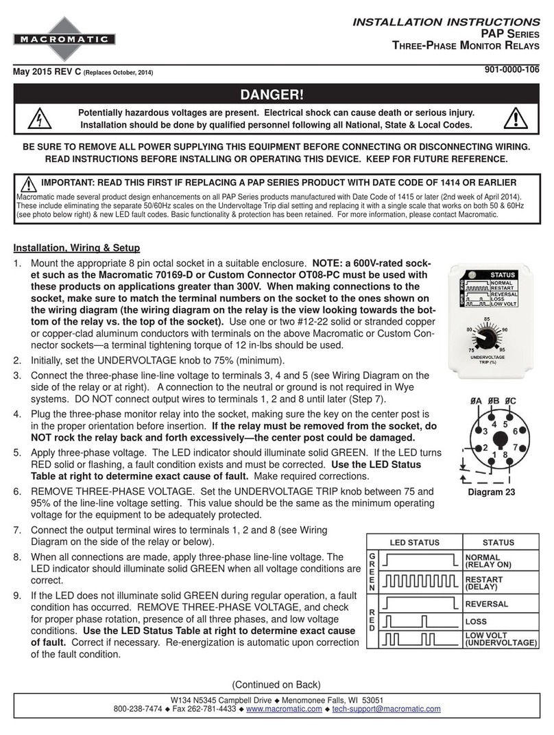
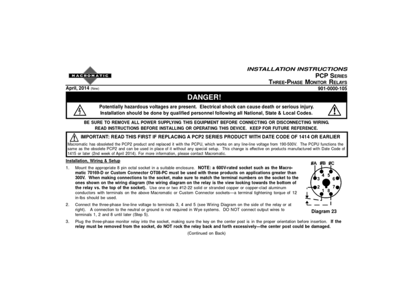
Installation, Wiring & Setup
1. Mount the appropriate 8 pin octal socket in a suitable enclosure. NOTE: a 600V-rated sock-
et such as the Macromatic 70169-D must be used with these products on applications
greater than 300V. When making connections to the socket, make sure to match the ter-
minal numbers on the socket to the ones shown on the wiring diagram (the wiring dia-
gram on the relay is the view looking towards the bottom of the relay vs. the top of the
socket). Use one or two #12-22 solid or stranded copper or copper-clad aluminum conductors
with terminals on the above Macromatic or Custom Connector sockets—a terminal tightening
torque of 12 in-lbs should be used.
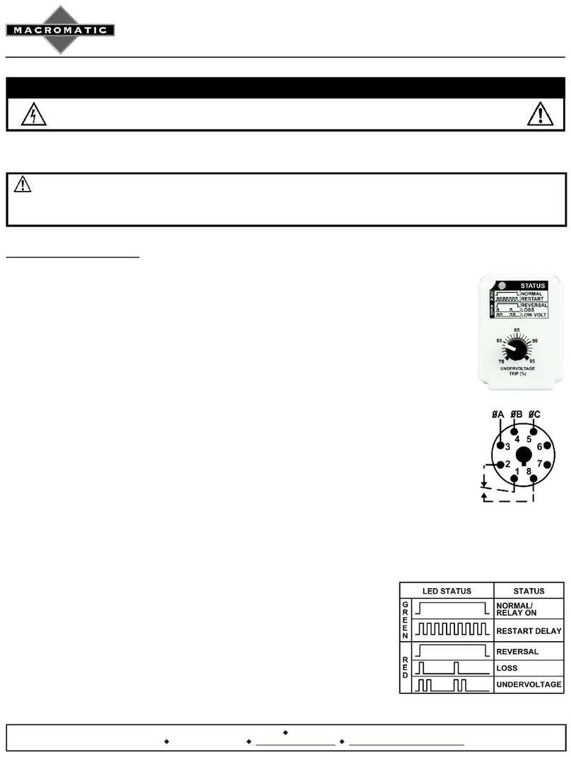
2. Initially, set the UNDERVOLTAGE knob to 75% (minimum).
3. Connect the three-phase line-line voltage to terminals indicated on Wiring Diagram on the
side of the relay or per diagrams below). A connection to the neutral or ground is not required
in Wye systems. DO NOT connect output wires to output terminals until later (Step 7).
4. Plug the three-phase monitor relay into the socket, making sure the key on the center post is
in the proper orientation before insertion. If the relay must be removed from the socket, do
NOT rock the relay back and forth excessively—the center post could be damaged.
5. Apply three-phase voltage. The LED indicator should illuminate solid GREEN. If the LED turns
RED solid or ashing, a fault condition exists and must be corrected. Use the LED Status
Table at right to determine exact cause of fault. Make required corrections.
6. REMOVE THREE-PHASE VOLTAGE. Set the UNDERVOLTAGE TRIP knob between 75 and
95% of the line-line voltage setting. This value should be the same as the minimum operating
voltage for the equipment to be adequately protected.
7. Connect the output(s) terminal wires to terminals 1, 2 and 8 (or 1,3,4 /11,8,9 for -11XSeries).
See Wiring Diagram on the side of the relay or diagrams below.
8. When all connections are made, apply three-phase line-line voltage. The
LED indicator should illuminate solid GREEN when all voltage conditions are
correct.
9. If the LED does not illuminate solid GREEN during regular operation, a fault
condition has occurred. REMOVE THREE-PHASE VOLTAGE, and check
for proper phase rotation, presence of all three phases, and low voltage
conditions. Use the LED Status Table at right to determine exact cause
of fault. Correct if necessary. Re-energization is automatic upon correction
of the fault condition.
(Continued on Back)
installation instructions


J3901-0000-106

Potentially hazardous voltages are present. Electrical shock can cause death or serious injury.

-
ING.
Macromatic Industrial Controls, Inc. • 2201 Corporate Drive • Waukesha, WI 53189
For product information and technical support go to www.macromatic.com/contact
Warranty
All catalog-listed PAP Series products manufactured by Macromatic are warranted to be free from defects in workmanship
or material under normal service and use for a period of ve (5) years from date of manufacture.
Typical 8 - pin Connections

Troubleshooting
If the unit fails to operate properly, check that all connections are correct per the appropriate wiring diagram on the
product. Check Troubleshooting table below. If problems continue, contact Macromatic at www.macromatic.com/contact for assistance.
Troubleshooting Guide
LED STATUS SITUATION SOLUTION
GREEN Motor is not
starting
The relay is in the run mode and working properly. Either
another control device is preventing the motor from starting or
all wiring should be checked.
NO INDICATION
Relay is not
energized and/
or motor is not
running
Verify L1, L2 and L3 (A, B & C) are connected to input termi-
nals per appropriate diagram below. Measure the three line-
to-line voltages. If any of the voltages are below the specified
minimum operation voltage, the relay does not have
enough power to operate. Check to
see why operating voltage is low and correct.
RED
On power-up
or with motor
running
The relay is sensing a phase reversal or phase out-of-sequence
(rotation) condition. REMOVE THREE-PHASE VOLTAGE
and switch any two of the three line connections to ensure the
phase sequence (rotation) is correct.
RED Phase loss Make sure all three phases are present. Check for a blown
fuse or a loose or broken wire.
RED Low voltage
(Undervoltage)
Measure the three line-to-line voltages. If the average of these
three voltages is below the UNDERVOLTAGE TRIP knob
setting, the relay has tripped due to a low voltage condition.
Check for low voltage condition and correct it.
Diagram 23
Macromatic Industrial Controls, Inc. • 2201 Corporate Drive • Waukesha, WI 53189
For product information and technical support go to www.macromatic.com/contact
installation instructions


Diagram 173
PAP - 11X Series

Other macromatic Relay manuals

macromatic PCP series User manual

macromatic

macromatic PCP series User manual

macromatic MDB Series User manual

macromatic

macromatic MDB Series User manual

macromatic TD-8 Series User manual

macromatic

macromatic TD-8 Series User manual

macromatic PMP Series User manual

macromatic

macromatic PMP Series User manual

macromatic CAP Series User manual

macromatic

macromatic CAP Series User manual

macromatic PAP Series User manual

macromatic

macromatic PAP Series User manual

macromatic COKP Series User manual

macromatic

macromatic COKP Series User manual

macromatic PAP Series User manual

macromatic

macromatic PAP Series User manual

macromatic Time Ranger TR-681 Series User manual

macromatic

macromatic Time Ranger TR-681 Series User manual

macromatic LCP Series User manual

macromatic

macromatic LCP Series User manual

Popular Relay manuals by other brands

Omron K8AK-AS manual

Omron

Omron K8AK-AS manual

Siemens 7UG0583-1CU20 operating instructions

Siemens

Siemens 7UG0583-1CU20 operating instructions

Hitachi PV-250 Installation operation & maintenance

Hitachi

Hitachi PV-250 Installation operation & maintenance

CTM LYNG MSB16 Photocell Installation and user instructions

CTM LYNG

CTM LYNG MSB16 Photocell Installation and user instructions

ABB RXHL 401 manual

ABB

ABB RXHL 401 manual

Rievtech PR-6DC-DA-R user manual

Rievtech

Rievtech PR-6DC-DA-R user manual

ABB CR324GXNS user guide

ABB

ABB CR324GXNS user guide

CALEFFI Z-one ZSR101 Series Wiring guide

CALEFFI

CALEFFI Z-one ZSR101 Series Wiring guide

Pickering PXI 4 145A Series manual

Pickering

Pickering PXI 4 145A Series manual

FANOX SIA-F user manual

FANOX

FANOX SIA-F user manual

ABB CR324CXCS user guide

ABB

ABB CR324CXCS user guide

GE NGV29A instructions

GE

GE NGV29A instructions

White Rodgers 120 Service instructions

White Rodgers

White Rodgers 120 Service instructions

Xylem CentriPro 9K585 instruction manual

Xylem

Xylem CentriPro 9K585 instruction manual

Energenie MIHO014 Fitting and wiring instructions

Energenie

Energenie MIHO014 Fitting and wiring instructions

TAMS RL-2 manual

TAMS

TAMS RL-2 manual

golmar SAR-12/18 manual

golmar

golmar SAR-12/18 manual

Omron G9SB datasheet

Omron

Omron G9SB datasheet

manuals.online logo
manuals.online logoBrands
  • About & Mission
  • Contact us
  • Privacy Policy
  • Terms and Conditions

Copyright 2025 Manuals.Online. All Rights Reserved.