For inquires or orders :
Safety Warnings : Please read the "Safety Warnings" in the instruction manual supplied with the instrument thoroughly and completely
for correct use. Failure to follow the safety rules can cause fire, trouble, electrical shock, etc. Therefore, make sure
to operate the instrument on a correct power supply and voltage rating marked on each instrument.
The contents of this leaflet are subject to change without notice. KEW 6305-3E Aug. 21 AD
2-5-20, Nakane, Meguro-ku, Tokyo, 152-0031 Japan
Phone:+81-3-3723-0131
Fax:+81-3-3723-0152
Wiring connections 1P2W, 1P3W, 3P3W, 3P3W3A, 3P4W
Measurements Voltage, Current, Frequency, Active power
Parameters
Apparent power, Reactive power, Active energy, Apparent energy,
Reactive energy, Power factor (cos θ), Neutral current
Voltage range
150.0/300.0/600.0V
Voltage accuracy ±0.2%rdg±0.2%f.s.
(sine wave, 45 - 65Hz)
Current range
10.00/50.00/100.0/250.0/500.0A/Auto
(
with clamp sensor MODEL8125
)
Current accuracy
±0.2%rdg±0.2%f.s.+ Accuracy of Clamp sensor
(sine wave, 45 - 65Hz)
*+1%f.s. at the lowest range.
Effective input range 10 - 110% of rating range
Display range 5 - 130% of each range (Voltage)
1 - 130% of each range (Current)
Crest factor Voltage : up to 2.5, Current : up to 3.0 (with 90% fs or less)
Active power accuracy ±0.3%rdg±0.2%f.s.+ Accuracy of Clamp sensor
*+1%f.s. when the lowest current ranges is selected.
Effect of power factor Active power: ±1.0%rdg cos θ=±0.5
(PF=1)
Frequency meter range 40.0 - 70.0Hz
Frequency meter accuracy ±3dgt
Accuracy precondition PF=1, Sine wave, 45 - 65Hz, 23℃±5℃
Display update period 1 second
Operating temperature and
humidity range 0 - +50℃, less than 85% RH
(without condensation)
Storage temperature and
humidity range -20 - +60℃, less than 85% RH
(without condensation)
PC communication interface USB, Bluetooth®
PC card interface SD card (2GB)
Safety standard IEC 61010-1 CAT Ⅲ600V
Power source (AC Line) AC100 - 240V±10%
(50/60Hz)
Power source (DC battery) LR6 or Ni-MH (HR-15-51)×6 (Battery charger not included),
Battery life approx. 15h (LR6)
Power consumption 10VA (ma x.)
Dimension
Weight
175
(L)× 120
(W)× 65
(D)
mm
Approx. 800g (including batteries)
Included accessories
7141B (Voltage test lead set: 4pcs), 7148 (USB cable),
7170 (Powercord),
9125 (Carrying case for KEW 6305, KEW 6305-01),
9135 (Carrying case for KEW 6305-03, KEW 6305-05),
8326-02 (SD card 2GB)
, KEW Windows (PC Software),
Battery (LR6)×6, Quick manual
Optional accessories
8124, 8125, 8126, 8127, 8128 (Clamp sensor),
8130, 8133, 8135 (Flexible clamp sensor),
8312 (Power supply adaptor), 9132 (Magnetic carrying case)
MODEL 9132MODEL 8312
MODEL 8128 MODEL 8127 MODEL 8126 MODEL 8125 MODEL 8124
MAX
50A φ24 MAX
100A φ24 MAX
200A φ40 MAX
500A φ40 MAX
1000A
φ68
KEW 8130KEW 8135 KEW 8133
MAX
1000A φ110 MAX
3000A φ17 0
MAX
50A φ75
Before connecting with the sensors KEW 8133 or KEW 8135, confirm that the
internal firmware version is later than the one listed in the table below.
The latest firmware is available on our website.
When using the sensor KEW 8135, confirm the serial number of the tester KEW
6305 is later than that is listed in the table below.
If your KEW 6305 has an earlier serial number than the one listed above, accuracy
will not be guaranteed when two or more KEW 8135 are connected with KEW 6305.
Supported serial numbers 8369312 or later
MODEL Firmware version
KEW 8133 V1.10 or later
KEW 8135 V2.00 or later
●KEW 6305 Specifications
Load current clamp sensors
Power supply adaptor Magnetic carrying case
Load current flexible clamp sensors
Optional
Set Model
For taking single phase supply
(100-240V) from the test leads to
power the instrument
For mounting inside
metal distribution
boards
KEW 6305-01
MODEL 8125 (500A) × 3
(Carrying case 9125)
KEW 6305-03
KEW 8130 (1000A) × 3
(Carrying case 9135)
KEW 6305-05
KEW 8133 (3000A) × 3
(Carrying case 9135)
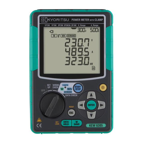
Can you close your distribution board door during surveys?
The KEW6305 facilitates safe testing by being extremely com-
pact and with two clever option extras: a magnetic case for
attaching it to the sides of metal enclosures and a power supply
adaptor which takes the power for the instrument from the sup-
ply being measured.
Photo: KEW6305-03
