(2)Pressthetrigger to open the transformerjaws
andclampontoaconductor. Themost
accuratereadingwillbeobtainedbykeeping
theconductor at the center of the transformer
jaws.
(3)Readthedisplay.
4-3ACVoltageMeasurement
WARNING
¡Neveruse the instrument on a circuitabove
600VrmsAC. Measurement oncircuitsabove
thisvoltageto the instrumentorequipment
undertest.
¡Keepyourfingersandhandsbehindthe
batteriesduringmeasurement.
¡Donotoperatetherangeswitchduringa
measurement.
¡Donot open the battery coverwhen making
measurement.
(1)Settherangeswitchto200Vor600V.
(2)InserttheredplugofthetestleadintotheV/Ω
terminalandtheblackplugintotheCOM
terminal.
(3)Touchthetips of the test leads to the circuit
undertest.
(4)Readthedisplay.
4-4
ResistanceMeasurementsandContinuityCheck
WARNING
¡Toavoid possibleelectrical shock and
instrumentdamage,makesurethatacircuitto
berestedisdeenergized.
¡Keepyourfingersandhandsbehindthe
barrierduringmeasurement.
¡Donotoperatetherangeswitchduringa
measurement.
¡Donot open the battery coverwhen making
measurement.
(1)Settherangeswitchto200Ω.
(2) InserttheredplugofthetestleadintotheV/Ω
terminalandtheblackplugintotheCOM
terminal.Withthetestleadsopen, thedisplay
shouldshow1onthehighestdigit(over
rangecondition)
(3) Short the test leads. The display should read
nearly0 and the beeper shouldsound. (Teas
leadhavearesistanceofabout0.2Ω)
WARNING
¡Readthrough and understandthe instructions
containedinthismanualbeforestartingtouse
theinstrument.
¡Saveand keep the manual at handtoenable
quickreferencewhenevernecessary.
¡Besuretousetheinstrumentonlyinits
intendedapplications.
¡Besuretounderstand andfollowallsafety
instructionscontainedinthemanual.
Besuretoobservetheaboveinstructions.
Failuretofollowtheaboveinstructionsmay
causeinjury,instrument Damageand/ordamage
toequipmentundertest.Kyoritsuisbynomeans
liable for any damage resulting from the
instrumentincontradictiontothese cautionary
notes.
○Thesymbol indicatedontheinstrument
meansthattheuser must refer to the related
partsin the manualforsafeoperation ofthe
instrument.
Besuretocarefullyreadtheinstructions
followingeach symbolinthemanual.
DANGER isreservedforconditionsand
actionsthatarelikelytocause
seriousorfatalinjury.
WARNING isreservedforconditionsand
actions that can cause serious or
fatalinjury.
CAUTION isreservedforconditionsand
actionsthatcancause injury or
instrumentdamage.
○Pleaserefertofollowingexplanationofthe
symbolsusedontheinstrumentandinthis
manual.
Usermustrefertotheexplanationsinthe
instructionmanual.
Indicates an instrument with double or
reinforcedinsulation.
Indicatesthat thisinstrumentcan clampon
bareconductorwhenmeasuringavoltage
correspondingto the applicable Measurement
category,whichismarkednexttothissymbol.
IndicatesAC(AlternatingCurrent).
IndicatesEarth.
○Readthrough the following safety instructions
containedinthismanualbeforeusingthe
instrument.
DANGER
¡Nevermakemeasurementonthecircuitinwhich
electricalpotentialtogroundover600Vexists.
¡Donotattempt tomakemeasurement inthe
presenceofflammablegasses. Otherwise,
the use of the instrument may cause
sparking,whichcanleadtoanexplosion.
¡Transformerjawtipsaredesignednotto
shortthecircuitundertest.Ifequipment
undertest hasexposedconductiveparts,
however,extraprecautionshouldbetakento
minimizethepossibilityofshorting.
¡Neverattemptto usetheinstrument ifits
surface or your hand is wet
.
Otherwise, you
maygetelectricalshock.
¡NeveropentheBottomcaseandBattery
coverduringameasurement.
(4)Connecttheleadstothecircuittobetestedand
readthedisplay.Thebeepersoundsbelow
about30Ω.
4-5HowtoUseDataHoldFunction
Onallranges,youcanholda readingonthe
displayusingDataHoldfunction.
(1)Whilemaking measurement, presstheData
Holdswitch. The last reading remains held on
thedisplay, with a Hold symbol shown
onthedisplay.
(2)Pressthe Data Hold switch again to exit from
DataHoldfunction.
WARNING
¡Toavoid electric shock hazard, make sure to
setthe range switch to OFFandremove
thetestleadsfromtheinstrumentbefore
try
ng
toreplacebattery.
IfsymbolBappearsonthedisplay,replacethe
batteryasfollows.
(1)Removetestleadsfromtheinstrumentandset
therangeswitchtoOFF
.
(2)Unscrewand remove the batterycompartment
cover.
(3)Replacethebatterywith anew9Vbattery,
Type1604,PP3, 6F22 orequivalent, observing
correctpolarity.
(4)Screwthebatterycompartmentcover.
Model8004 and8008(Multi-Tran)extendthe
existing current measuring range and the
maximumconductorsize.
(1)Settherangeswitchto200Aor600A
(2)ClampaMulti-Tranonaconductortobetested.
(3)ClampKEWSNAP 2017 or 2027 on thepick-
upcoiloftheMulti-Tran.
(4)Readthedisplayandmultiplythereadingby
10.
WARNING
¡Neverattempttomakeanymeasurementifthe
instrumenthasanystructuralabnormalitysuch
ascrackedcaseandexposedmetalpart.
¡Donot turn therangeswitch with restleads
connectedtotheinstrument.
¡Donotinstallsubstituteparts ormakeany
modificationtotheinstrument.Returnthe
instrumenttothedistributorfrom whom you
purchasedthisinstrumentforrepairorre-
calibration.
¡Alwaysswitchofftheinstrumentbefore
openingthebatterycompartmentcoverfor
batteryreplacement.
CAUTION
¡Alwaysmake sure to setthe Rangeswitch to
the appropriate position before making
measurement.
¡Alwaysmake sureto insert theplug of each
leadfully intothe appropriate terminal on the
instrument.
¡Besuretosetthe RangeswitchtoOFF
positionafteruse.Whentheinstrumentwillnot
beinusefora long period, place itinstorage
afterremovingthebatteries.
¡Donotexposetheinstrumenttothedirectsun,
hightemperatureandhumidityordewfall.
¡Usea damp cloth and detergent for cleaning
theinstrument.Donotuseabrasivessolvents.
○Measurement categories (Over-voltage
categories)
To ensure safe operation of measuring
instruments,IEC61010establishessafety
standardsforvariouselectricalenvironments,
categorizedas CATItoCATIV,andcalled
measurementcategories. These are defined as
indicatedonthenext.
CAT.Ⅰ:Secondaryelectricalcircuitsconnectedto
anAC electrical outletthrough a transformer
orsimilardevice.
CAT.Ⅱ: Primaryelectricalcircuitsofequipment
connectedtoanACelectricaloutletbya
powercord.
CAT.Ⅲ:Primaryelectricalcircuitsoftheequipment
connecteddirectlyto the distributionpanel,
andfeedersfrom thedistributionpanelto
outlets.
CAT.Ⅳ: The circuitfrom the service dropto the
serviceentrance,andtothepowermeterand
primaryover-currentprotectiondevice
(distributionpanel).
¡DesignedtoCAT.Ⅲ 600Vandpollutiondegree
2specified bythe internationalsafety standard,
IEC61010-1.
¡Tear-drop-shapedjawsforeaseofusein
crowdedcableareasandothertightplaces.
¡DataHoldfunction.
¡Widefrequencyrangefrom40Hzto1kHz.
¡KEWSNAP2027isatrueRMSTypethat
permits most accurate measurements
independentofwaveforms.
1. SafetyWarnings
○This instrument has been designed,
manufactured,andtestedaccordingtoIEC
61010:SafetyrequirementsforElectronic
measuringapparatus, anddelivered in the best
conditionafterpassedtheinspection.
Thisinstruction manual contains warnings and
safetyruleswhichmustbeobservedbytheuser
toensuresafeoperationoftheinstrumentandto
retainitinsafecondition.
Therefore, read through these operating
instructionsbeforeusingtheinstrument.
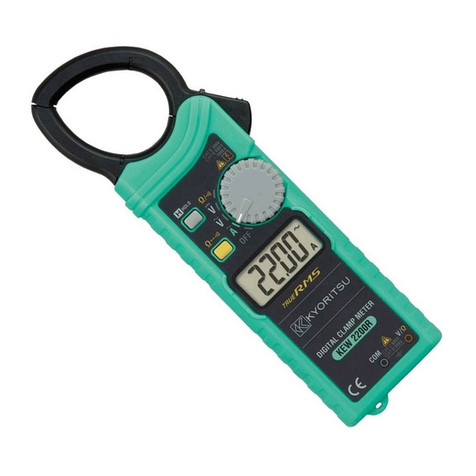
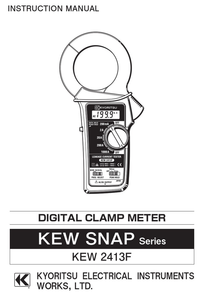
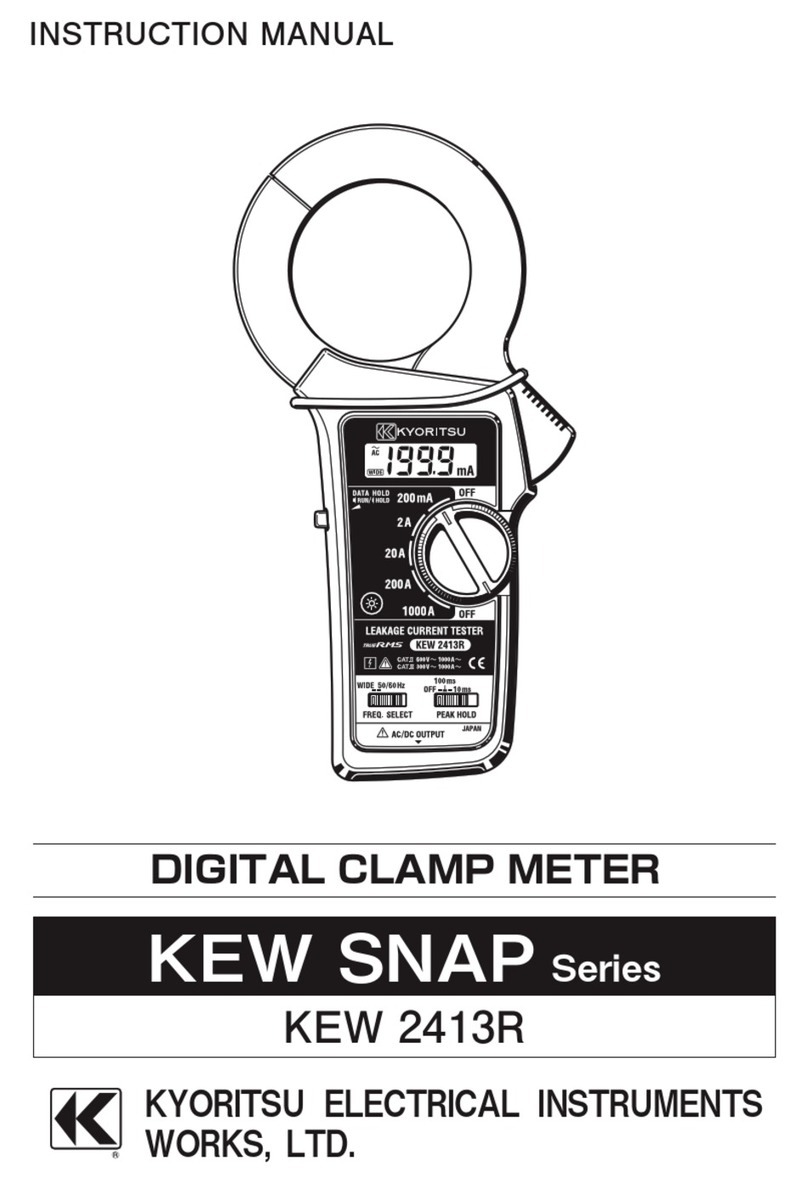
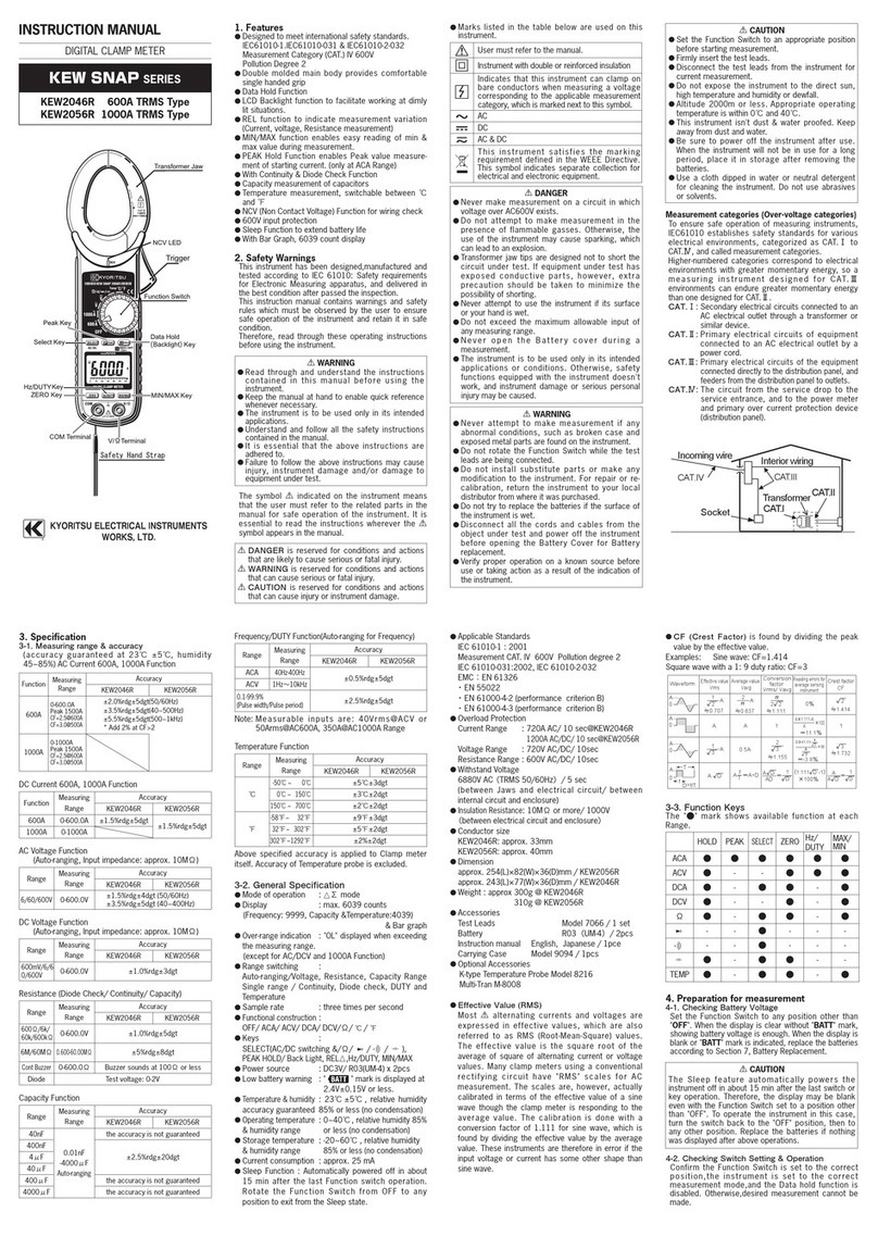
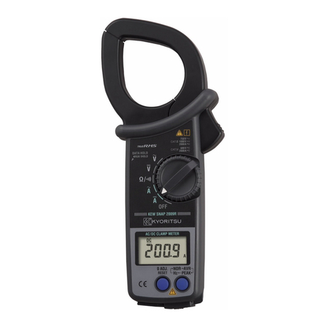
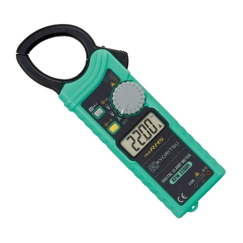
KEWSNAPSERIES
KEWSNAP2017
KEWSNAP2027RMS
INSTRUCTIONMANUAL
DIGTALACCLAMPMETER
¡Effectofconductorposition:
2017 Within2%ofindicatedvalueatthecenter
toa 10mm‐dia conductor carrying 100A,
ateverypartinsidethejaws.
2027 Within3%ofindicatedvalueatthecenter
toa 10mm‐dia conductor carrying 100A,
ateverypartinsidethejaws.
¡Effectof external: 2A orless in AC magnetic
fieldofmagneticfield400A/m
¡PowerSource:6F22(9VDC)or equivalent
battery
¡BatteryLife:Approx.200hours(continuous)
¡Currentconsumption:Approx.2mA
¡WithstandingVoltage :5550VAC for 1 minute
betweenhousingcaseand
metalpartofjaws
¡InsulationResistance : 50MΩ or greaterat
1000Vbetweenhousing
caseandmetalpartof
jaws
¡ConductorSize:Approx.30mmdiametermax.
¡Dimensions:Approx.91(W)×208(H)×40(D)mm
¡Weight:Approx.400g(batteriesincluded)
¡SafetyStandard:EN61010-1
EN61010-031
EN61010-2-032
(600VACCAT.Ⅲ,Pollutiondegree2,indooruse)
¡EMCStandard:EN55022
¡Accessories:TestleadsModel7066 ……1set
6F22battery …………………1
CarryingcaseModel9079 …1
InstructionManual …………1
¡OptionalAccessories:Clamp adapter Model
8004,8008
4-1Preparationtocheckbatteryvoltage;
(1)Settherangeswitchtoadesiredposition
(2)IfthedisplayisclearwithoutsymbolB
showing, proceedto measurement,Battery
voltageisOK.
(3)IftheDisplayblinksorsymbolBisindicated,
replacethe battery inaccordance with Section
5forBatteryReplacement.
4-2ACCurrent Measurement
WARNING
¡Keepyourfingersandhandsbehindthe
barrierduringmeasurement.
¡Do notmake measurement with thebattery
coverremovedfromtheinstrument.
¡Pleasebesuretoremove ameasurement
codebeforemeasurement.
(1)Settherangeswitchto200Aor600A.
Forfurtherinformation,readtheinstruction
manualforthesemodels.
¡Cleaning
Useaclothdippedinwaterorneutraldetergent
forcleaningtheinstrument.
Donotuse abrasives orsolvents,Otherwise,
instrument get damaged, deformed or
discolored.
DISTRIBUTOR
Kyoritsu reserves the rights to change
specificationsordesignsdescribedinthis
manualwithoutnoticeandwithoutobligations.
4.OperatingInstruction
2.Features
¡OperatingSystem:DualIntegration
¡Display:Liquidcrystalwithamaxcountof1999
¡Overrangindication:1is displayedonthe
highestdigit.
¡Responsetime:Approx.2seconds.
¡Locationforuse:Altitudeup to 2000mor less,
in-dooruse
¡TemperatureandHumidity:23℃±5℃
relativehumidity
(GuaranteedAccuracy)75%orless.
(nocondensation)
¡Operatingtemperature:‐10〜50℃,
(nocondensation)
upto30℃,95%relativehumidity
upto40℃,75%relativehumidity
upto50℃,45%relativehumidity
¡StoragetemperatureandHumidity:
‐20〜60℃,(nocondensation)
relativehumidity75%orless
3.Specification
KEWSNAP2017
Ranges
AC200A 50/60Hz
40Hz〜1kHz
50/60Hz
40Hz〜1kHz
50/60Hz
40Hz〜1kHz
50/60Hz
40Hz〜1kHz
1.5%rdg+4dgt
2.0%rdg+5dgt
1.0%rdg+3dgt
2.0%rdg+5dgt
1.0%rdg+2dgt
1.5%rdg+4dgt
1.0%rdg+2dgt
1.5%rdg+4dgt
sin
↑
↑
↑
↑
↑
↑
↑
AC600A
AC200V
AC600V
200Ω 1.2%rdg+2dgt、Beepsbelowabout30Ω.
Frequency Accuracy
CrestFactor
KEWSNAP2027(TrueRMSType)
Ranges
AC200A 50/60Hz
40Hz〜1kHz
50/60Hz
40Hz〜1kHz
50/60Hz
40Hz〜1kHz
50/60Hz
40Hz〜1kHz
1.5%rdg+4dgt
2.0%rdg+5dgt
1.5%rdg+4dgt
2.0%rdg+5dgt
1.0%rdg+2dgt
1.5%rdg+4dgt
1.0%rdg+2dgt
1.5%rdg+4dgt
≦3
sin
≦3
sin
≦3
sin
≦3
sin
AC600A
AC200V
AC600V
200Ω 1.2%rdg+4dgt、Beepsbelowabout30Ω.
Frequency Accuracy
CrestFactor
5.BatteryReplacement
6.OptionalAccessories
7.Maintenance
Model
MODEL8004
Φ60
Φ100
AC0〜1000A
AC0〜3000A
10:1
10:1
MODEL8008
MAX.ConductorSize.
MeasuringRange
InputtoOutputRatio
Overrangelndication
11−11 92−1281E
