manuals.online logo
Brands
  1. Home
  2. •
  3. Brands
  4. •
  5. KYORITSU
  6. •
  7. Test Equipment
  8. •
  9. KYORITSU 3165 User manual

KYORITSU 3165 User manual

MANUAL DE INSTRUCCIONES
1.- PRECAUCIONES DE SEGURIDAD
Este Manual contiene advertencias y reglas de seguridad que
deben considerarse, para el uso y operación seguros del instrumento y
mantenerlo en buenas condiciones. Por lo tanto, lea este instructivo de
operación completamente y a fondo antes de usar el instrumento.
El simbolo ¡ en el instrumento, significa que debe rrecurrir a una
sección relevante de este manual para una operación segura del
instrumento.
1
Ponga mucha atención a todas las ADVERTENCIAS y
PRECAUCIONES indicadas en este manual.Las
ADVERTENCIAS son para evitar choques eléctricos y las
PRECAUCIONES son para evitar dañar el equipo.
1. Siempre asegurese de insertar los plugs de las puntas hasta el
fondo de las terminales de el instrumento.
2. Nunca exceda el maximo rango permitido de cualquier medición
cuando haga sus mediciones.
3. Asegurese de nunca aplicar un voltaje mayor a los 600V C.A. ó
C.D. entre terminal de línea y terminal de tierra.
4. Nunca trate de operar el instrumento en atmosferas explosivas. (en
presencia de gases flameables o humo, vapor o polvo).
5. Siempre inspeccione el instrumento, puntas de prueba y todos los
accesorios para detectar cualquier daño o anormalidad antes de
cada uso. Si existen condiciones anormales, (puntas de prueba
rotas, cuartiaduras en el instrumento, etc…), No trate de hacer
mediciones.
6. No presione el botón de prueba o dejelo probando, si no ha
conectado las puntas de prueba.
7. No toque el circuito bajo prueba durante la prueba de aislamiento.
8. Asegurese de quitar las puntas de prueba y que el instrumento este
apagado antes de abrir el compartimento de las pilas para
reemplazarlas.
9. Siempre apague el aparato después de usarlo.
10. No exponga el instrumento al sol, rocio o temperaturas extremas.
11. No exponga el instrumento a temperaturas mayores de los 50ºC
12. Para calibración y reparación de cualquier instrumento, este debe
ser llevado con el personal calificado y capacitado tecnicamente
para esta tarea.
13. No instale o sustituya partes o no realice sin autorización
modificaciones al instrumento. Regrese el instrumento a su
distribuidor para servicio y reparación para que usted este seguro
de un buen mantenimiento
14. El Instrumento debe ser usado correctamente, por personal
entrenado y con estricto apego a las instrucciones.
KYORITSU no aceptara ser responsable del mal menejo
e incumplimiento de los procedimientos de seguridad y
de las instrucciones. Es escencial que lea y entienda las
reglas de seguridad de las instrucciones. Necesitara de ellas
cuando haga uso del instrumento.
2.- CARACTERISTICAS.
-Puede medir voltaje C,A. sin presionar el boton de prueba.
-Checar batería facilmente.
-Usa solo 4 baterías de 1.5V tipo R6, AA o equivalentes.
3.- ESPECIFICACIONES.
-Medicion con exactitud (23±5ºC, humedad rel. 45-75%)
Rangos de Resistencia de Aislamiento
MOD. 3165 MOD. 3166
Voltaje de prueba 500 V 1000V
Rango a medir 1000MΩ2000MΩ
Valor media escala 20MΩ50MΩ
Salida de voltaje en
circuito abierto
Clasificación de la prueba de
voltaje +20% - 0%
Salida de corriente
de corto crcuito
230 µA max. 450 µA max.
1-500 MΩ:
±5% de lectura
2-1000 MΩ:
±5% de lectura
Exactitud
±0.7% de la longitud de la escala
a otros rangos de medición
Advertencia de Voltaje C.A.
Advertencia de Rango. 0-600 VC.A.
Exactitud ±3% de la longitud de esc.
Fuente de Energía: 4 pilas tipo AA o equivalentes
Protección de Sobrecarga: Rangos de Resistencía de
Aislamiento.
Mod. 3165: 600V(CD+CA p-p) por10seg.
Mod. 3166: 1200V(CD+CA p-p)por10seg.
Rango de Voltaje en CA
720V (CD+CA p-p) por 10 seg.
Temperatura de
Operación y humedad: 0-40ºC, humedad relativa 85%
Voltaje de Soporte: 3700V CA por un minuto, entre el
circuito Eléctrico y la carcasa.
Resistencia del
Aislamiento: Más de 50MΩa 1000V entre los
Circuitos electricos y la carcasa.
Dimensiones: 90(L)x137(W)x40(D)mm
Peso: 330gr
Accesorios Puntasde prueba Mod. 7025( 1 set)
Funda para las puntas (1pza.)
Correa ( 1 pza.)
Baterías R6 (4 pzas.)
Manual (1 copía).
4.- OPERACIÓN.
4.1.PREPARACIÓN PARA LAS PRUEBAS.
2
(1) Ajuste Mecánico a Cero.
Sin presionar el botón de prueba, cheque que la aguja quede
aliniada con la marca de ∞en la escala roja de megaohm, si
no es así, ajustela por medio del tornillo de ajuste a cero.
(2) Conexión de las puntas de prueba.
Inserte las puntas de prueba a las terminales del instrumento.
(3) Checar las Baterias
Las baterías se checan por medio de parpadeo del LED de prueba de las
baterías, este parapadeo se da a la hora de las pruebas del Aislamiento,
esto indica que las baterías estan en buen estado.
(4) Checar Puntas de Prueba.
Presione el botón de prueba, y girelo hacía la derecha. Cuando las
puntas de prueba esten conectadas, juntelas, la aguja se movera desde ∞
hasta la posición 0 al otro extremo de la caratula de megaohm. Si no es
así, tal vez las puntas esten mal conectadas, regrese el botón de prueba
a su posición y repita el procedimiento.
¡ADVERTENCIA!
Cuando el botón de prueba este presionado, no toque el instrumento
ni las puntas de prueba, ya que hay presencía de alto voltaje y corre el
riesgo de sufrir un choque electrico.
4.2. FUNCIÓN DE ADVERTENCIA VOLTAJE C.A.
(1)La presencía de voltaje, puede ser detectada. Esta función opera
automaticamente Cuando el botón de prueba aún no se presiona, i.e. se
encuentra en su posición normal.
(2)Usando las puntas de prueba, conecte la terminal de tierra a tierra y
la terminal de línae a la línea del circuito que se va a probar.
(3) Tome la lectura de la escala del Voltaje.
4.3. MEDICIÓN DE RESISTENCIA DE AISLAMIENTO.
¡ADVERTENCIA!
Para evitar choques electricos, no toque las puntas
de prueba ni el circuito a medir.
PRECAUCIÓN!
Para evitar dañar el instrumento, Haga la medición
del Aislamiento solo en circuitos desenergizados.
Asegurese de que el circuito o equipo a probar este
desconectado antes de proceder a hacer la
medición del Aislamiento.
(1) Conecte las puntas de prueba al instrumento y al
circuito a probar.
¡ADVERTENCIA!
(2) Cheque que el circuito a probar no este energizado y
prosiga. Conecte las puntas de prueba al circuito a
probar y lea el valor del voltaje.
Si el circuito esta vivo el medidor indicara el voltaje.
Si el valor es de 0V, el circuito esta muerto.
(3) Presione el botón de prueba. Lea directamenta la
escala roja de megaohm.
*Continuamos Midiendo.
Ooserve las caracteristicas mencionadas en la parte
de abajo del botón de prueba. Presionelo y girelo en
sentido de las manesillas del reloj, esto para que el
aparato se mantenga midiendo.
Nunca gire el botón si el aparato no esta en uso.
(4) Descargando la capacitancia del circuito probado.
Es probable que el circuito quede cargado despues de
haberlo inducido con el voltaje del aparato. Para
descargar el circuito inducido, invierta la conexión de
la linea y la tierra. Podra observar cargas restantes en
la escala de Voltaje.
¡ADVERTENCIA!
No toque el circuito bajo prueba despues de
haberlo probado, ya que pudo quedar cargado y
esto ocasionaria un choque eléctrico.
5.- REEMPLAZO DE LAS BATERIAS
. ¡ADVERTENCIA!
Para evitar choques electricos de peligro,
desconecte las puntas de prueba.
Nunca presione el botón de prueba cuando haya presencía de voltaje
en el circuito que se va a probar.
Para reemplazar las baterías, primero desconecte todas las puntas de
prueba del instrumento. Abra el portapilas para sacar las pilas que ya no
sirvan y sustituirlas. Las cuatro pilas deben ser de tipo AA de 1.5V.
Siempre reemplase las cuatro pilas al mismo tiempo por unas nuevas.
Nunca mezcle pilas nuevas con viejas, apriete bien el tornillo del
portapilas antes de volver a usar el instrumento.
6.- MANEJO DE LA CARCASA Y LOS ACCESORIOS.
6.1 Tapa de la carcasa
Puede colocar la tapa de la carcasa como se muestra un el siguiente
dibujo:
6.2. Como ajustr la correa y Los cables de prueba a la bolsa.
1. Ajuste la correa como se muestra enseguida:
2. Coloque las puntas de pruebea en su bolsa como se muestra
enseguida.
7.- SERVICIO Y CALIBRACIÓN.
Si este probador falla o no opera correctamente, regreselo a
su distribuidor, para asegurarse de la naturaleza exacta de la
avería, Asegurese de lo suiguiente:
a.- Esta siguiendo correctamente los pasos indicados en este
manual.
b.- Los cables han sido inspeccionados.
c.- Las baterías han sido checadas
d.- La unidad debe de llevar todos los accesorios.
Nota: puesto que a la cubierta del medidor se le ha dado un
tratamiento contra estática no lo frote fuertemente para
quitar el polvo o la suciedad. Si hay presencia de carga
electrostatica en la carcasa, limpielo con un paño suave
mojado con la solución contra estática.
Toda la información aquí presentada, es con derechos
reservados de KYORITSU.
3
SCALEPLATE
POWERON
LED
BATTERY
CHECKLED
TESTBUTTON MOVEMENTZEROADJUST
INPUT
TERMINALS
ANALOGUE INSULATION TESTERS
3165
MODEL
3166
INSTRUCTION MANUAL 1. Always make sure to insert the plug of test leads fully into the terminal
of the instrument.
2. Never exceed the maximum allowable input of any measuring range
when making measurement.
3. Make sure to never apply a voltage more than 600V AC or DC between
the terminal of the instrument and earth.
4. Never try to operate the instrument in an explosive atmosphere ( i. e.
in the presence of flammable gases or fumes, vapor or dust).
5. Always inspect the instrument, test leads and accessories for any sign
of damage or abnormality before every use. If abnormal conditions
exist (e. g. broken test leads, cracked enclosure of the instrument), do
not try to make measurements.
6. Do not push the test button or lock it down while connecting test leads.
7. Do not touch the circuit under test during insulation testing.
8. Make sure to remove the test lead from the instrument and turn the
power off before opening the battery compartment cover for battery
replacement.
9. Always turn the power off after use.
10. Do not expose the instrument to the direct sun, dew fall, or extreme
temperatures.
11. Do not expose the instrument to a temperature of more than 50℃.
12. Calibration and repair of any instrument should only be performed by
qualified and trained service technicians.
13. Do not install substitute parts or perform any unauthorized
modification of the instrument. Return the instrument to your
distributor for service and repair to ensure that safety features are
maintained.
14. The instrument must be used by a competent, trained person and
operated in strict accordance with the instructions. KYORITSU
will not accept liability for any damage or injury caused by misuse
or noncompliance with the instructions or safety procedures. It is
essential to read and understand the safety rules contained in the
instructions. They must be observed when using the instrument.
2. Features
●AC voltage measurement can be made without depressing the test
button.
●Battery check facility.
●Uses only 4×1.5V battery type R6, AA or equivalent.
3. Specifications
●Measuring ranges accuracy(at 23±5℃, relative humidity 45-75%)
Insulation resistance ranges:
MODEL 3165 MODEL 3166
Test voltage
500V 1000V
Measuring range
1000MΩ2000MΩ
Mid-scale value
20MΩ50MΩ
Output voltage on
open circuit Rated test voltage +20%-0%
Output short
circuit current 230μA max 550μA max
Primary Effective
Measuring Range
1~500MΩ2~1000MΩ
Accuracy
±5% of indicated value at primary effective
measuring range
±0.7% of scale length at 0 and ∞
±10% of indicated value at other measuring range
AC Voltage Warning:
Warning range 0-600V AC
Accuracy ± 3%of scale length
Power supply 4×1.5V battery type SUM-3,R6,AA or equivalent
Overload protection Insulation Resistance Ranges
Model 3165: 600V (DC+ACp-p) for 10 seconds
Model 3166:1200V (DC+ACp-p) for 10 seconds
AC Voltage Range
720V (DC+ACp-p) for 10 seconds
Operating temperature & humidity
0-40℃, relative humidity up to 85%
Storage temperature & humidity
-10-50℃, relative humidity up to 75%
Withstand voltage 3700V AC for one minute between electrical
circuit and housing case
Insulation resistance More than 50MΩat 1000V between electrical
circuit and housing case
Dimensions 90(L)×137(W)×40(D)mm
Weight 330g
Accessories Test leads Model 7025(1 set)
Pouch for test leads (1 piece)
Shoulder strap (1 piece)
R6 batteries (4 pieces)
Instruction manual (1 copy)
4. Operation
4-1 Preparation for testing
(1)Mechanical zero adjustment
Without pressing the Test button, check that the pointer lines up with
CAUTION
Never press
test button
1. Safety Precautions
●This instruction manual contains warnings and safety rules that must
be observed by the user to ensure safe operation of the instrument and
retain it in safe condition. Therefore, read these operating instructions
thoroughly and completely before using the instrument.
●The symbol #on the instrument means that the user must refer to
the relevant section of this instruction manual for safe operation of the
instrument.
●Pay particular attention to all WARNINGS and CAUTIONS in this
instruction manual. WARNING indicates warnings to avoid electrical
shock and CAUTION indicates cautions to avoid damage to the
instrument.
the ∞mark on the red megaohm scale. If not, adjust it by rotating
the meter movement zero adjust with a screwdriver.
(2)Test lead connection
Insert the test leads into the terminals of the instrument.
(3)Battery voltage check
Battery check LED flashes at insulation resistance testing to indicate
normal battery condition.
Replace the batteries when the LED stops flashing.
Replace the batteries according to section 6 for battery replacement.
(4)Test leads check
Press and turn the Test button to lock it down. When the test leads
are connected together, the pointer should move from the ∞position
towards the 0 position on the megaohm scale. If not, the leads may be
faulty. Release the Test button after completion.
#WARNING
When the Test button is pressed, take care not to touch the tip of the
test lead where a high voltage is present in order to avoid possible
shock hazard.
4-2 AC Voltage Warning Function
#WARNIING
Never depress the test button when voltage is present on the circuit
under test.
(1)The presence of AC voltage can be detected. This function operates
automatically when the test button is not depressed, i.e., in the up
position.
(2)Using the test leads, connect EARTH terminal to the earth side of the
circuit under test and LINE terminal to the line side.
(3)Take the reading on the AC voltage scale.
4-3 Insulation Resistance Measurement
#WARNING
To avoid electrical shock, do not touch the test lead tips and the
circuit under test during measurement.
#CAUTION
To avoid damage to the instrument, insulation measurement must be
performed on de-energized circuits only. Make sure that the circuits
or equipment is disconnected before proceeding with an insulation
test.
(1)Connect the test leads to the instrument and the circuit under test.
(2)Check the circuit under test is not energized as follows.
  Connect the test leads to the circuit under test and read a voltage
value.
If the circuit is live, the meter indicates the voltage.
If the meter indicates 0V, the circuit is dead.
(3)Press test button. Read the red megaohm scale directly.
●Continuous Measurement
A lock down feature is incorporated on the test button. Pressing and
turning it clockwise lock the test button in the continuous operating
position.
To release the lock turn the test button counter clockwise.
Never leave the test button locked down when not in use.
(4)Discharging capacitance of circuit under test.
It is possible that capacitance has been stored in the circuit under test
after insulation testing. To discharge the circuit capacitance reverse
the connection of the earth clip and line probe. Remaining electric
charges can be observed on AC voltage warning range.
#WARNING
Do not touch the circuit under test immediately after testing.
Capacitance stored in the circuit may cause electric shock.
5. Battery Replacement
#WARNING
To avoid shock hazard disconnect the test leads from the
instrument.
To replace the batteries, first disconnect all test leads from the instrument.
Open the battery compartment cover by unscrewing the metal captive
screw to reveal battery compartment. The four 1.5V SUM-3(R6)type
batteries are located in a compartment. Always replace all four batteries
with new ones at the same time. Never mix old and new ones. Screw the
battery compartment lid back on before using the instrument.
6. Notes on Housing Case & Accessories
6-1 Case Lid
Case lid can be fit under the housing case as illustrated bellow.
1) Open the case lid as shown.
2) Turn it 180 degrees.
3)
Put the case lid under the housing case.
4) Hook it on to the housing case.
6-2 How to fit Neck Strap & Test lead Pouch
1. Fit the neck strap as shown.
2. Fit the test lead pouch to the housing case as shown.
7. Servicing & Calibration
If this tester should fail to operate correctly. return to your distributor,
stating exact nature of fault. Make sure that:-
a. Operating instructions have been followed
b. Leads have been inspected
c. Batteries have been checked
d. The unit is returned with all accessory leads
Note : Since the meter cover has been given an anti-static treatment do not
rub it strongly with dr y cloth to remove dust or dirt. If electrostatic
charges are present on the cover. wipe it with a soft cloth wet with
anti-static solution.
KYOURITSU reserves the right to change specifications without prior
notice.
CAUTION
Alwaysturnoffbreaker
incircuitundertest
beforeinsulationtest.
Connectearthprobeto
earthterminal
#CAUTION
Install battery in correct
polarity as marked inside
the case.
Fixing Screw
Neck strap
Buckle
Buckle Fixing Button
Tighten
Strap
Test Lead pouch
4-12 92-1331A

This manual suits for next models

1

Other KYORITSU Test Equipment manuals

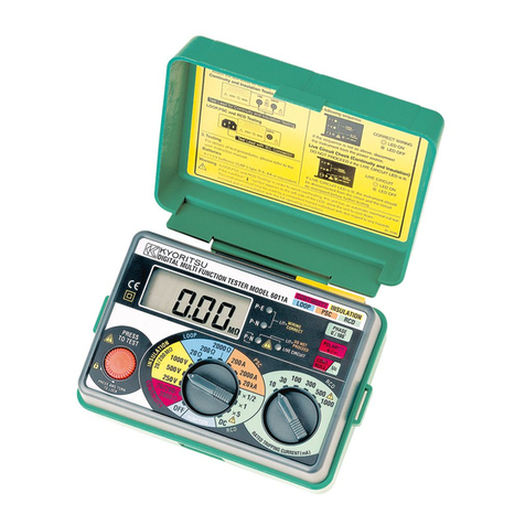
KYORITSU 6011A User manual

KYORITSU

KYORITSU 6011A User manual

KYORITSU 8128 User manual

KYORITSU

KYORITSU 8128 User manual

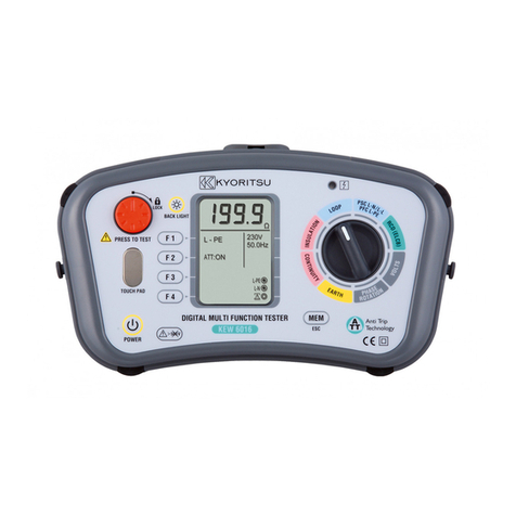
KYORITSU 6017 User manual

KYORITSU

KYORITSU 6017 User manual

KYORITSU KEW 6010B User manual

KYORITSU

KYORITSU KEW 6010B User manual

KYORITSU 3021A User manual

KYORITSU

KYORITSU 3021A User manual

KYORITSU KEW 3127 User manual

KYORITSU

KYORITSU KEW 3127 User manual

KYORITSU 3321A User manual

KYORITSU

KYORITSU 3321A User manual

KYORITSU 6050 User manual

KYORITSU

KYORITSU 6050 User manual

KYORITSU 4116A Guide

KYORITSU

KYORITSU 4116A Guide

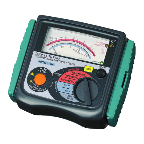
KYORITSU 3131A User manual

KYORITSU

KYORITSU 3131A User manual

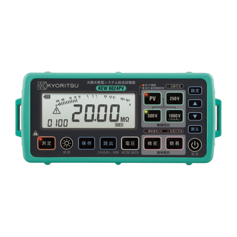
KYORITSU KEW6024PV User manual

KYORITSU

KYORITSU KEW6024PV User manual

KYORITSU KEW 8146 User manual

KYORITSU

KYORITSU KEW 8146 User manual

KYORITSU KEW8031F User manual

KYORITSU

KYORITSU KEW8031F User manual

KYORITSU KEW 3121A User manual

KYORITSU

KYORITSU KEW 3121A User manual

KYORITSU 5406A User manual

KYORITSU

KYORITSU 5406A User manual

KYORITSU 6010A User manual

KYORITSU

KYORITSU 6010A User manual

KYORITSU 3132A User manual

KYORITSU

KYORITSU 3132A User manual

KYORITSU KEW FORK 2300 R User manual

KYORITSU

KYORITSU KEW FORK 2300 R User manual

KYORITSU 4118A User manual

KYORITSU

KYORITSU 4118A User manual

KYORITSU KEW3431 User manual

KYORITSU

KYORITSU KEW3431 User manual

KYORITSU KEW 3022 User manual

KYORITSU

KYORITSU KEW 3022 User manual

KYORITSU KEW3125A User manual

KYORITSU

KYORITSU KEW3125A User manual

KYORITSU K8031F User manual

KYORITSU

KYORITSU K8031F User manual

KYORITSU KEW FORK User manual

KYORITSU

KYORITSU KEW FORK User manual

Popular Test Equipment manuals by other brands

Tektronix 502 series Service manual

Tektronix

Tektronix 502 series Service manual

SIC EXPANDER user manual

SIC

SIC EXPANDER user manual

Wetekom 81 48 65 Original instructions

Wetekom

Wetekom 81 48 65 Original instructions

Phenix Technologies PM15-2 Operation and application manual

Phenix Technologies

Phenix Technologies PM15-2 Operation and application manual

MONARCH INSTRUMENT Nova-Pro Series instruction manual

MONARCH INSTRUMENT

MONARCH INSTRUMENT Nova-Pro Series instruction manual

Voltech DC1000A quick start guide

Voltech

Voltech DC1000A quick start guide

ANCEL AJ600 GDI Piezo quick start guide

ANCEL

ANCEL AJ600 GDI Piezo quick start guide

Fluke 712C Quick reference guide

Fluke

Fluke 712C Quick reference guide

Fluke TP1000 Safety information

Fluke

Fluke TP1000 Safety information

WIKA Wally Box III operating instructions

WIKA

WIKA Wally Box III operating instructions

KPS KPS-MA100 instruction manual

KPS

KPS KPS-MA100 instruction manual

Rigol DS70000 Series manual

Rigol

Rigol DS70000 Series manual

Ametek Jofra MTC-650 A MKII Reference manual

Ametek

Ametek Jofra MTC-650 A MKII Reference manual

HOGERT HT8G432 user manual

HOGERT

HOGERT HT8G432 user manual

Hanna Instruments HI 98204 instruction manual

Hanna Instruments

Hanna Instruments HI 98204 instruction manual

GEMAC CAN-Bus Tester 2 user manual

GEMAC

GEMAC CAN-Bus Tester 2 user manual

Intepro systems ELR 10000 4U Series operating guide

Intepro systems

Intepro systems ELR 10000 4U Series operating guide

Getz Equipment Innovators 4G58589 quick start guide

Getz Equipment Innovators

Getz Equipment Innovators 4G58589 quick start guide

manuals.online logo
manuals.online logoBrands
  • About & Mission
  • Contact us
  • Privacy Policy
  • Terms and Conditions

Copyright 2025 Manuals.Online. All Rights Reserved.