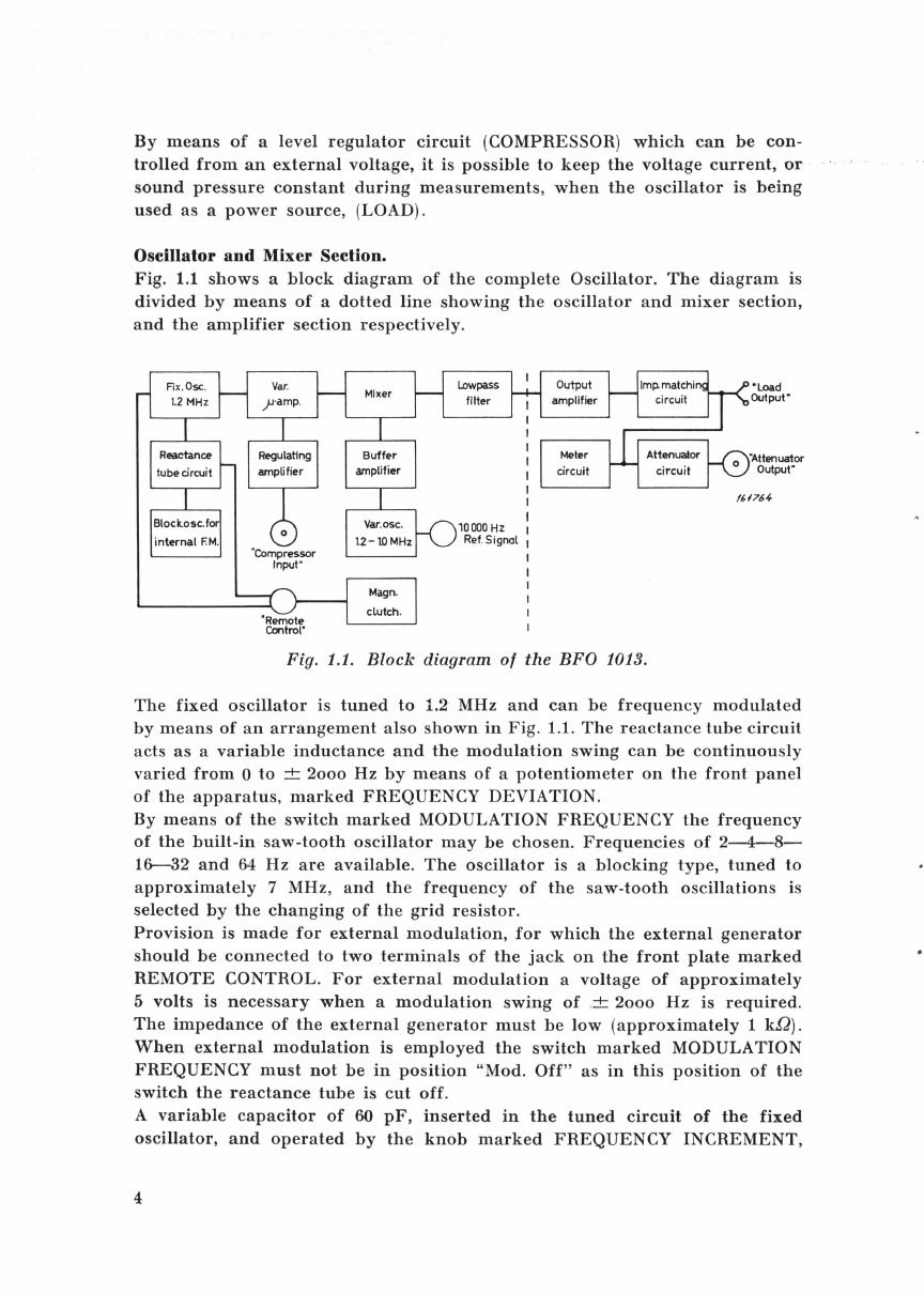
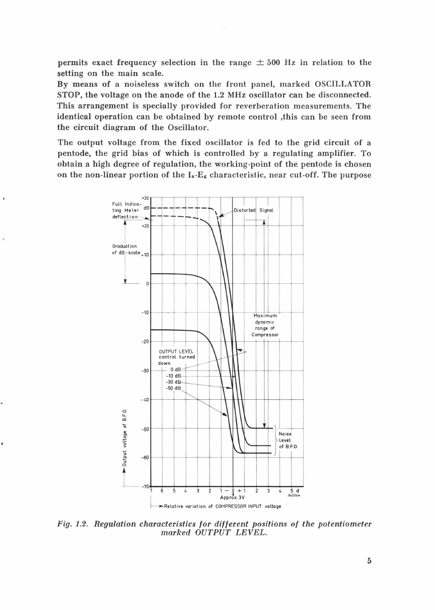
BRUEL & KJAER 1013 User guide

Beat Frequency Oscillator Type
1013
·a
,.
,.
~
A Beat
Frequency
Osciilator
covering
the
range
200
to
200ooo
Hz. The
instrument
is
designed
to
meet
the
numerous
requirements
of
a
signal
source
for
audio
and
supersonic
frequency
work
.
It
is
excellently
suited
both
for
electrical
and
electro-acoustical
measurements,
as
well
as
for
acoustic
and
supersonic
research.
BRUEL&KJ&R
Naerum. Denmark .
ey;j;
80
05
00
.
.;:;:'"
BRUKJA, Copenhagen . Telex: 5316
BB
1018


Beat Frequency
Oscillator
Type 1013
NOVEMBER
1965

Contents.
Page
1.
Description
. . . . . . . . . . . . . . . . . . . . . . . . . . . . . . . . . . . . . . . . . . . . . . . . . . . . . . . 3
General
. . . . . . . . . . . . . . . . . . . . . . . . . . . . . . . . . . . . . . . . . . . . . . . . . . . . . . . . . . 3
Oscillator
and
Mixer
Section
. . . . . . . . . . . . . . . . . . . . . . . . . . . . . . . . . . . . . . 4
Partial
Blocking
of
Frequency
Range
. . . . . . . . . . . . . . . . . . . . . . . . . . . . . . 7
Output
Amplifier
Section
. . . . . . . . . . . . . . . . . . . . . . . . . . . . . . . . . . . . . . . . . . 8
Power
Supply
. . . . . . . . . . . . . . . . . . . . . . . . . . . . . . . . . . . . . . . . . . . . . . . . . . . . 9
2.
Control
Knobs,
Terminals
and
Shafts
. . . . . . . . . . . . . . . . . . . . . . . . . . . . . . .
11
3.
Operation
..............................
.
.........
.
....
..
.........
14
General
.....
.
...........................................
.
........
14
A.
Frequency
Calibration
. . . . . . . . . . . . . . . . . . . . . . . . . . . . . . . . . . . . . . . . . .
14
B.
Operation
Using
the
Output
Terminals
marked
LOAD
............
15
C.
Operation
Using
the
Built-in
Output
Attenuator
..................
15
D.
Frequency
Modulation
. . . . . . . . . . . . . . . . . . . . . . . . . . . . . . . . . . . . . . . . . . 15
E.
Automatic
Recording
. . . . . . . . . . . . . . . . . . . . . . . . . . . . . . . . . . . . . . . . . . .
17
F.
Partial
Blocking
of
Frequency
Range
............................
19
G.
Automatic
Regulation
of
the
Output
Power
. . . . . . . . . . . . . . . . . . . . . .
21
H.
Remote
Control
. . . . . . . . . . . . . . . . . . . . . . . . . . . . . . . . . . . . . . . . . . . . . . . . 22
I.
Trouble
Shooting
. . . . . . . . . . . . . . . . . . . . . . . . . . . . . . . . . . . . . . . . . . . . . . 22
4.
Combined
Units
..
.
.............
..
.............................
.
..
24
Automatic
Frequency
Response
Recorder
Type
3306 . . . . . . . . . . . . . . . . . . 24
Automatic
Frequency
Response
Recorder
Type
3328
............
.
.....
25
5.
Applications
. . . . . . . . . . . . . . . . . . . . . . . . . . . . . . . . . . . . . . . . . . . . . . . . . . . . . . 28
Electronic Measurements . . . . . . . . . . . . . . . . . . . . . . . . . . . . . . . . . . . . . . . . . . 28
Frequency
Response
Measurements
of
Four
Terminal
Networks
......
28
AC
Bridge
Measurements
. . . . . . . . . . . . . . . . . . . . . . . . . . . . . . . . . . . . . . . . . . 29
Automatic
Recording
of
Electrical
Impedance
....
.
.................
30
Frequency
Response
of
High
Quality
Amplifiers
. . . . . . . . . . . . . . . . . . . . 31
Acoustical Measurements
.........
. . .
..............................
32
Frequency
Response
of
Loudspeakers
(Tweeter) . . . . . . . . . . . . . . . . . . . . 32
Directional
Characteristics
of
Loudspeakers
. . . . . . . . . . . . . . . . . . . . . . . . 34
Recording
of
the
Frequency
Response
of
Sound
Projectors
..........
35
Directional
Characteristics
of
Projectors
................
.
...........
36
Recording
of
Frequency
Response
of
Hydrophones
.
.................
39
Mechanical Measurements . . . . . . . . . . . . . . . . . . . . . . . . . . . . . . . . . . . . . . . . . . 40
Automatic
Recording
of
Accelerometer
Frequency
Response
. . . . . . . . . . 40
6.
Specifications
. . . . . . . . . . . . . . . . . . . . . . . . . . . . . . . . . . . . . . . . . . . . . . . . . . . . . 42

Description.
Gt>neral.
The
Beat
Frequency
Oscillator
Type
1013 is
designed
for
measurements
in
the
frequency
range
200-200ooo
Hz
and
consists
of
an
oscillator,
mixer,
and
an
amplifier
section.
It
works
on
the
heterodyne
principle
using
two
high-frequency
oscillators,
one
of
which
operates
on
a
fixed
frequency,
while
the
frequency
of
the
other
can
be
varied
by
means
of
a
variable
capacitor.
The
required
signal
frequency
is
obtained
as
the
difference
between
the
two
high
frequencies
and
can
be
read
off
a
large
illuminated
scale,
the
pointer
of
which
is
connected
to
the
variable
capacitor.
The
scale
is
logarithmic
and
graduated
from
200
to
200ooo
Hz,
and
in
addition
an
INCREMENTAL
SCALE
is
provided,
allowing
exact
frequency
selection
in
the
range
-500
to
+500
Hz
for
any
setting
on
the
main
scale.
The
frequency
adjustment
is
carried
out
by
obtaining
a
beat
between
the
fourth
harmonic
of
the
line
voltage
and
the
oscillator
voltage,
occurring
when
the
oscillator
is
tuned
to
this
frequency
and
the
push
-
button
marked
LINE
FREQUENCY
BEAT
FOURTH
HARMONIC
on
the
front
panel
is
pressed.
The
variable
capacitor
has
two
control
knobs,
one
of
which
is
directly
connected
to
the
capacitor
spindle
and
is
used
for
quick
setting
of
the
approximate
frequency.
The
other
will,
when
pressed,
rotate
the
spindle
with
a
ratio
of
1
to
5
and
allow
fine
tuning
to
the
desired
frequency.
A
worm
gear
permits
the
capacitor
to
be
tuned
automatically,
for
example
by
the
aid
of
the
motor
in
the
Level
Recorder
Type
2305.
The
mechanical
connection
to
the
Level
Recorder
is
effected
by
means
of
a
flexible
shaft
which
can
be
screwed
onto
the
bushing
on
the
side
of
the
Oscillator
cabinet.
The
worm
gear
can
be
engaged
and
released
with
the
aid
of
a
built-in
electromagnetic
clutch,
operated
from
a
switch
on
the
front
panel
marked
AUTOMATIC
SCANNING
or
by
a
remote
control
arrangement
.
The
electro-
magnetic
clutch
is
a
friction
device,
so
that
manual
tuning
of
the
variable
capacitor
is
possible
even
when
the
clutch
is
engaged.
The
Beat
Frequency
Oscillator
is
provided
with
frequency
modulation.
A
reactance
tube,
controlled
by
saw-tooth
oscillations
from
a
built-in
oscillator,
may
be
switched
into
the
circuit
of
the
fixed
oscillator.
The
frequency
of
the
saw-tooth
oscillator
is
controlled
by
the
switch
marked
MODULATION
FREQUENCY,
and
the
amplitude
of
the
saw-tooth
oscillations,
which
controls
the
frequency
deviation,
is
regulated
by
FREQUENCY
DEVIATION.
Provision
is
also
made
for
external
modulation
whereby
very
wide
limits
of
frequency
modulation
can
be
obtained.
3

By
means
of
a
level
regulator
circuit
(COMPRESSOR)
which
can
be
con-
trolled
from
an
external
voltage,
it
is
possible
to
keep
the
voltage
current,
or
sound
pressure
constant
during
measurements,
when
the
oscillator
is
being
used
as
a
power
source,
(LOAD).
Oscillator
and
Mixer
Section.
Fig. 1.1
shows
a
block
diagram
of
the
complete
Oscillator.
The
diagram
is
divided
by
means
of
a
dotted
line
showing
the
oscillator
and
mixer
section,
and
the
amplifier
section
respectively.
Fig. 1.1.
Block
diagram
of
the
BFO
1013.
The
fixed
oscillator
is
tuned
to
1.2· MHz
and
can
be
frequency
modulated
by
means
of
an
arrangement
also
shown
in
Fig.
1.1.
The
reactance
tube
circuit
acts
as
a
variable
inductance
and
the
modulation
swing
can
be
continuously
varied
from
0
to
±
2ooo
Hz
by
means
of
a
potentiometer
on
the
front
panel
of
the
apparatus
,
marked
FREQUENCY
DEVIATION.
By
means
of
the
switch
marked
MODULATION
FREQUENCY
the
frequency
of
the
built-in
saw-tooth
oscillator
may
be
chosen.
Frequencies
of
2-4-8-
16-32
and
64
Hz
are
available.
The
oscillator
is a
blocking
type,
tuned
to
approximately
7 MHz,
and
the
frequency
of
the
saw-tooth
oscillations
is
selected
by
the
changing
of
the
grid
resistor.
Provision
is
made
for
external
modulation,
for
which
the
external
generator
should
be
connected
to
two
terminals
of
the
jack
on
the
front
plate
marked
REMOTE
CONTROL.
For
external
modulation
a
voltage
of
approximately
5
volts
is
necessary
when
a
modulation
swing
of
.±
2ooo
Hz
is
required.
The
impedance
of
the
external
generator
must
be
low
(approximately
1 k.Q).
When
external
modulation
is
employed
the
switch
marked
MODULATION
FREQUENCY
must
not
be
in
position
"Mod.
Off"
as
in
this
position
of
the
switch
the
reactance
tube
is
cut
off.
A
variable
capacitor
of
60
pF,
inserted
in
the
tuned
circuit
of
the
fixed
oscillator,
and
operated
by
the
knob
marked
FREQUENCY
INCREMENT,
4

permits
exact
frequency
selection
in
the
range
.± 500
Hz
in
relation
to
the
setting
on
the
main
scale.
By
means
of
a
noiseless
switch
on
the
front
panel,
marked
OSCILLATOR
STOP,
the
voltage
on
the
anode
of
the
1.2 MHz
oscillator
can
be
disconnected.
This
arrangement
is
specially
provided
for
reverberation
measurements.
The
identical
operation
can
be
obtained
by
remote
control
,this
can
be
seen
from
the
circuit
diagram
of
the
Oscillator.
The
output
voltage
from
the
fixed
oscillator
is
fed
to
the
grid
circuit
of
a
pentode,
the
grid
bias
of
which
is
controlled
by
a
regulating
amplifier.
To
obtain
a
high
degree
of
regulation,
the
working-point
of
the
pentode
is
chosen
on
the
non-linear
portion
of
the
Ia-Eg
characteristic,
near
cut-off.
The
purpose
•30
Full
Indica-
t i
ng
Me
t
er
dB
deflection
--........
•20
Graduation
'"
[·
':
-
10
-20
-30
- 40
0
u.:
a:i
'li -50
0
>
::J
Q.
-60
::J
0
-
70
I I
--
--
--
--
~",
v
Distorted
Signal
---
--
.,
\
1--
\\
-.......,_
\\
~
\\
\ Maximum
dynamic
1\
range
of
""'\
C
ompressor
OUTPUT
LEVEL
~ ~
t::!:
control
turned
~
:n
0
dB
____.-
-----
-10 dB- \
1\\
-30dB-
_ -
r---
~
-50
dB
,
~
""'
~
~
\~
1
\
r
-~
\\.~
No
i
se
~
level
-of B.
F.a
.
7 6 5 4 3 2
1-~+1
2 3 4
L
Approx
.
3V
5 d
/6
22
61-
Relative
vari
ation
of
COMPRES
S
OR
INPUT
voltage
Fig. 1.2.
Regulation
characteristics for
different
positions
of
the
potentiometer
marked
OUTPUT
LEVEL.
5

of
this
circuit
is
to
control
automatically
the
output
of
the
Beat
Frequency
Oscillator
by
applying
an
external
voltage.
The
external
control
voltage
should
be
fed
into
the
screened
jack
marked
COMPRESSOR
INPUT
on
the
front
panel
of
the
Oscillator.
A
variable
potentiometer,
marked
COMPRESSOR
VOLTAGE is
inserted
in
the
input
circuit
of
the
regulating
amplifier
and
can
be
used
as
level
control
for
the
output
from
the
Oscillator,
when
automatic
regulation
is
employed.
The
regulating
amplifier
has
a
linear
frequency
characteristic
from
200
to
200ooo
Hz
and
should
have
an
input
signal
of
approximately
3
volts
on
the
grid
of
the
amplifier
tube
for
full
regulation.
The
input
impedance,
measured
across
the
terminals
of
the
jack
marked
COMPRESSOR
INPUT
is
approx
-
imately
10
kohms,
and
the
obtainable
range
of
regulation
is
at
least
45 dB.
The
amplified
control
voltage
is
rectified
in
a
full-wave
double-diode
rectifier,
designed
to
give a DC
output
voltage
proportional
to
the
average
value
of
the
control
voltage.
The
speed
of
regulation
can
be
varied
with
the
switch
marked
COMPRESSOR
SPEED
on
the
front
panel
of
the
Oscillator.
Regulation
speeds
of
30-
100-
300
or
1ooo
dB/
sec
may
be
chosen
by
changing
the
value
of
the
capacitor
in
the
R-C
filtering
network
for
the
rectified
control
voltage.
When
the
switch
COMPRESSOR
SPEED
is
in
position
COMP.
OFF
the
output
from
the
recti-
fier
is
short-circuited
thereby
disconnecting
the
automatic
regulation.
It
is
also
possible
to
obtain
different
regulation
characteristics
dependent
on
the
position
of
the
potentiometer
marked
OUTPUT
LEVEL.
This
can
be
seen
from
Fig.
1.2.
To
obtain
good
regulation
even
when
maximum
output
power
is
required
from
the
Oscillator,
the
level
of
the
high
frequency
voltage
from
the
1.2 MHz
fixed
Oscillator
is
raised
approximately
10 dB
when
the
automatic
regulation
is
switched
in.
The
anode-circuit
of
the
pentode
in
the
variable
,
a-amplifier
is
tuned
to
1.2 MHz,
thereby
forming
a
band-pass
filter,
the
output
of
which
is
fed
to
the
mixer.
The
frequency
of
the
variable
oscillator
can
be
continuously
altered
from
1.2
MHz
to
1.0 MHz
by
means
of
a
specially
designed
variable
capacitor.
This
capacitor
is
made
with
a
high
degree
of
accuracy
and
a
maximum
deviation
of
o.7
degrees
from
a
logarithmic
frequency
curve
is
obtained.
The
Frequency
Main
Scale
can
be
remotely
scanned
via
a
mechanical
drive.
The
arrangement
is
intended
to
be
driven
from
the
B & K
Level
Recorder
Type
2305
via
the
Flexible
Shaft
UB 0041
(1
meter).
In
this
manner
the
frequency
scan
of
the
B.F.O.
can
be
driven
in
synchronism
with
the
pre-print
of
the
recording
paper
of
the
Level
Recorder.
The
built-in
worm
gear,
having
a
ratio
of
50 :1,
causes
a
scale
pointer
movement
corresponding
to
one
octave,
when
the
input
drive
of
the
B.F.O.
turns
through
three
revolutions
.
The
worm
gear
can
be
set
and
released
by
a
magnetic
slutch
which
is
operated
from
a
switch
(AUTOMATIC SCANNING)
on
the
front
panel
of
the
6

Oscillator,
or
it
can
also
be
operated
from
an
external
switch
or
relay.
In
the
latter
case
connection
must
be
made
to
the
appropriate
terminals
of
the
jack
marked
REMOTE
CONTROL
on
the
front
panel,
and
the
control
switch
AUT. SCANNING
for
the
magnetic
clutch
must
be
in
position
"Off".
By
means
of
a
pushbutton
marked
10ooo
Hz
REF.
SIGNAL,
an
extra
capacitor
is
introduced
in
the
tuning
circuit
of
the
variable
oscillator.
There
viii
be
exactly
lOooo
Hz
at
the
output
socket
when
the
scale
pointer
is
set
to
10ooo Hz
REF.
SIGNAL
and
the
pushbutton
10ooo
REF.
SIGNAL
is
depressed.
The
reason
for
setting
the
scale
pointer
at
10ooo
Hz
REF.
SIGNAL is
in
order
to
be
able
to
align
the
1013
with
the
frequency
calibrated
paper,
used
on
the
Level
Recorder
Type
2305,
as
this
paper
is
calibrated
from
10 Hz.
The
distance
between
the
calibration
mark
of
10 Hz
and
20 Hz
on
the
recording
paper
corresponds
to
the
distance
between
1oooHz
REF.
SIGNAL
and
200Hz
on
the
oscillator.
By
depressing
the
pushbutton
it
is
now
possible
to
check
that
the
level
of
the
middle
frequencies
is
within
the
divisions
of
the
paper.
The
voltage
developed
across
the
grid
circuit
of
the
variable
oscillator
is
fed
to
the
mixer
tube
via
a
buffer
amplifier
stage.
This
stage,
which
prevents
undesired
coupling
between
the
fixed
and
variable
oscillator,
also
increases
the
signal
level
to
a
value
required
for
correct
functioning
of
the
mixer.
The
mixer
tube
is a
triode
giving a
low
hum
level
in
spite
of
the
AC
heating
of
the
filament.
A
low-pass
filter
with
a
cut-off
frequency
of
500
kHz
is
inserted
in
the
anode
circuit
of
the
mixer
tube,
passing
only
the
lower
frequency
obtained
by
the
frequency
conversion
to
the
grid
circuit
of
the
first
tube
in
the
output
amplifier
section.
Partial Blocking
of
Frequency Range.
As
previously
mentioned,
the
frequency
scale
is
logarithmic
and
calibrated
20Q-20ooo
Hz.
When
the
capacitor
is
set
to
frequencies
above
20ooo Hz
or
below
200
Hz
the
fixed
Oscillator
can
be
blocked,
and
consequently
no
output
voltage
will
be
obtained.
For
automatic
recording
of
frequency
characteristics,
i.e.
when
using
the
Level
Recorder
Type
2305,
this
is a
great
advantage
as
no
unwanted
curves
will
then
appear
on
the
corresponding
section
of
the
frequency
calibrated
paper.
The
cut-off
section
can
be
made
wider
by
adjusting
the
cam
discs,
connected
to
the
rear
end
of
the
capacitor
spindle.
It
is
possible
to
cut
down
the
fre-
quency
range
to
approximately
one
octave
in
any
part
of
the
range
of
200-200ooo
Hz.
However,
if
the
REMOTE
CONTROL
plug
is
removed
there
will
be
no
blocking
at
any
part
of
the
scale.
In
application
where
the
B.F.O. is
employed
in
conjunction
with
the
B & K
Level
Recorder,
and
where
automatic
recording
is
required,
the
blocking
arrangement
can
also
be
used
for
remote
lifting
of
the
Level
Recorder's
writing
pen.
This
is a
great
asset
in
for
example
measurements
where
the
7

compressor
circuit
of
the
B.F.O. is
used.
In
this
instance
the
pen-lifting
arrangement
of
the
Level
Recorder
can
be
controlled
from
the
frequency
blocking
circuit
by
making
the
appropriate
connections
to
the
REMOTE
CONTROL
jack
of
the
B.F.O.
In
cases
where
the
entire
frequency
range
(200-200ooo
Hz)
of
the
B.F.O. is
utilized,
the
normal
frequency
blocking,
which
functions
outside
the
scale
graduation,
should
be
set
out
of
operation.
The
writing
pen
of
the
Level
Recorder
can
now
be
lifted
from
the
paper
outside
the
frequency
range
of
interest
and
a
proper
working
of
the
com-
pressor
also
at
the
initial
frequency
(2QO
Hz) is
ensured
during
the
automatic
scan.
If
the
described
methods
is
not
utilized,
the
following
would
take
place:
No
signal
will
be
present
in
the
range
200ooo
Hz
to
200
Hz
(outside
the
scale
graduation),
i.e.
the
compressor
of
the
B.F.O.
will
be
in
such
a
condition
to
give
full
output
signal
of
the
B.F.O.
Consequently,
when
the
scale
pointer
goes
inside
the
scale
graduation
(200 Hz)
full
output
level
will
be
transmitted
at
200Hz,
and
after
the
chosen
time
delay
(COMPRESSOR
SPEED)
the
signal
level
will
be
compressed
to
the
proper
(preset)
value.
A
deflection
on
the
recording
paper
which
is
not
a
response
of
the
measured
object
would
thus
be
recorded.
Output Amplifier Section.
The
voltage
from
the
low-pass
filter
is
fed
to
the
control
grid
of
the
first
tube
in
the
two-stage
output
amplifier
via
a
variable
potentiometer.
This
potentiometer
is
operated
by
the
knob
marked
OUTPUT
LEVEL
on
the
front
panel
of
the
Oscillator
and
is
used
for
continuous
adjustment
of
the
output
power.
The
gain
of
the
amplifier
is
stabilized
by
negative
voltage
feedback.
The
anode
circuit
of
the
output
tube
is
coupled
to
the
impedance
matching
circuit.
Four
different
output
impedances
are
available
and
can
be
chosen
by
the
switch
on
the
front
panel
marked
MATCHING
IMPEDANCE.
The
different
positions
of
the
switch
are
indicated
by
6, 60, 600
and
6ooo
ohms
respectively
and
the
output
voltage
is
taken
from
the
terminals
marked
LOAD.
It
should
be
noted
that
the
output
impedance
of
the
Oscillator
is
only
approximately
20 %
of
the
indicated
values,
but
with
correct
loading
maximum
power
output
is
obtained
with
minimum
harmonic
distortion
(Fig. 1.3).
In
addition,
correct
loading
ensures
the
output
voltage
to
be
independent
of
the
frequency
to
within
± 1
dB
for
frequencies
between
200
and
200ooo Hz. A
fifth
position
of
the
switch
MATCHING
IMPEDANCE
is
marked
"Att."
and
connects
the
output
transformer
to
an
attenuator,
variable
in
steps
of
10 dB
from
400
fA-VOlts
to
12.5 volts.
The
attenuator
is
operated
by
the
switch
marked
ATTENUATOR
on
the
front
panel.
In
this
position
of
the
impedance
switch
the
output
circuit
is
connected
to
the
screened
jack
on
top
of
the
front
panel.
The
output
impedance
is
constant
and
approximately
50
ohms.
The
accuracy
of
the
attenuator
is
better
than
± 2
%.
The
voltage
on
the
output
terminals
is
indicated
by
a
vacuum-tube
voltmeter
8

which
measures
the
average
value
of
the
output
voltage.
It
is
calibrated
in
RMS
values
for
sinusoidal
voltages.
The
sensitivity
of
the
voltmeter
is
automatically
changed
when
the
position
of
the
switch
marked
MATCHING
IMPEDANCE
is
altered.
Full
deflection
of
the
meter
is
indicated
on
the
switch.
In
addition
to
the
volt
calibration
on
the
switch
ATTENUATOR
OUTPUT
there
is
also
a
dB
calibration
,and
the
cali-
bration
is,
as
mentioned
above,
given
in
dB
re.
1
volt.
An
example
will
ex-
plain
the
use
of
the
dB
scale:
If
the
OUTPUT
LEVEL
is
adjusted
in
such
a
way,
that
20
dB
is
read
on
the
meter
scale,
and
the
switch
ATTENUATOR
OUTPUT
is
in
the
position
-
30
dB
then
the
signal
level
at
the
output
socket
will
be
20-30
=
-10
dB
re.
1
volt
(o.316 V).
When
the
MATCHING
IMPEDANCE
switch
is
in
position
"Att."
the
output
voltage
available
from
the
ATTENUATOR
OUTPUT
will
depend
on
the
position
of
the
ATTENUATOR
OUTPUT
switch,
in
this
case
full
deflection
of
the
meter
corresponds
to
the
value
indicated
by
the
switch
position.
The
signal-to-noise
ratio
of
the
Oscillator
is
greater
than
70
dB
for
maximum
output
voltage.
By
"noise"
is
here
meant:
The
root
mean
square
of
internally
induced
noise,
hum
and
spurious
frequencies
.
1.5
% 7
~-
I I v
/
LOAD:
2.
5wotts
/
_,-"
I
f.
0.7
g
0.5
~
(II
:0
g 0.3
~~
~)<
v
i-
1
LOAD
:1
watt
~
~
......
""
.....
,
~
~---
---
1-
--
~
-::/
~
'', •
~
J
\ I
"-,
/"" /
' ,/
~
~"
_,
/"
/
"r-...
\
_.,....
c
::r
0.2
\1
v..
ATTEN
1
~~~~~
OUT~UT
5
z
L
0.15
0.1
0.1 0.2 0.5 1
10
20
kHz
50
100
200
500
~
Frequency
f62.?62
Fig. 1.3.
Distortion
curves for
different
loads.
The
curve
marked
»Att. 5 Volts"
is
obtained
from
measurements
taken
on
the
ATTENU
ATOR
OUTPUT terminal,
open
circuited. ·
Power
Supply.
The
Oscillator
can
be
operated
from
a 240, 220, 150, 127, 115
or
100
volts
AC,
50--400
Hz
power
line,
the
power
consumption
being
about
70
watts.
The
proper
voltage
is
selectable
by
a
switch-fuse
combination
situated
at
the
rear
of
the
instrument.
To
select
the
voltage
it
is
necessary
to
remove
the
fuse
by
turning
the
hexagonal
disc
head
in
the
centre
of
the
switch
anticlock·
9

wise.
Then
with
a
coin
turn
the
head
of
the
voltage
adjuster
until
the
white
mark
is
aligned
with
the
required
voltage.
The
fuse
is
then
replaced.
It
should
be
noted
that
if
the
apparatus
is
to
be
operated
from
a DC
power
line,
or
from
an
accumulator,
a
vibrator
unit
or
a
rotary
converter
is
required.
10

2.
Control Knobs, Terminals and Shafts
Power
Ground
Oscillator
Stop Frequency
Deviation
Indicating Meter
Compressor
Speed
10
000
C/S
Ref
. Signal Frequency
Scale
Alignment
Load
Compressor
Voltage
162263
Fig. 2.1.
Beat
Frequency
Oscillator
Type
1013.
Power:
LINE
FREQUENCY
BEAT
FOURTH
HARMONIC:
When
switched
to
"On"
the
meter
scale
and
fre-
quency
scales
will
be
illuminated.
Pushbutton,
when
pressed
and
held
in, a
beat
be
-
tween
power
supply
frequency
and
output
fre-
quency
of
the
B.F.O.
can
be
observed
on
the
in
-
11

AUTOMATIC
SCANNING:
FREQUENCY
MAIN
SCALE:
FREQUENCY
INCREMENT:
SHAFT
CONNECTION
for
MECHANICAL
DRIVE:
MODULATION
FREQUENCY:
OSCILLATOR
STOP:
REMOTE
CONTROL:
MODULATION
DEVIATION:
12
dicating
meter.
By
this
arrangement
the
output
frequency
can
be
brought
to
coincide
with
the
calibration
of
the
Frequency
Main
Scale.
This
switch,
when
in
the
On"
position,
allows
the
variable
capacitor
of
the
B.F.O.
to
be
connected
to
a
worm
drive
which
can
be
connected
to,
and
driven
from
an
external
motor.
Logarithmic.
Indicates
the
output
frequency
when
the
B.F.O. is
frequency
calibrated
by
the
LINE
FREQUENCY
BEAT
arrangement
and
Frequency
In-
crement
Scale
is
set
to
"0".
This
makes
available
exact
frequency
selection
in
the
range
-500
to
+500
Hz
for
the
setting
on
the
Frequency
Main
Scale.
FREQUENCY
INCREMENT
setting
is
readable
on
the
Frequency
Increment
Scale.
Located
on
both
sides
of
the
instrument
for
the
connection
of
an
external
mechanical
driving
source
for
automatic
frequency
sweep.
The
Shaft
Connec-
tion
fits
the
Flexible
Shaft
UB
0041
which
forms
the
mechanical
link
between
the
B.F.O.
and
the
Level
Recorder
Type
2305.
Switch
allows
the
frequency
of
a
built-in
blocking
type
oscillator
which
is
used
to
frequency
modulate
the
oscillator
output
signal
to
be
set
to
2-4--8-
16--32
and
64 Hz.
This
unit
is
specially
installed
for
reverberation
measurements
and
is a
noiseless
switch
which
dis-
connects
the
anode
voltage
of
the
fixed
oscillator.
Beneath
the
cap
is
provided
six
terminals
for
the
connection
of
various
external
forms
of
remote
control
and
external
frequency
modulation.
Method
of
connection
is
fully
explained
under
paragraph
"
Remote
Control".
By
utilizing
a
reactanc
e
-tube
circuit
as
a
variable
inductance
the
fixed
oscillator
can
be
frequency
modulated
with
a
modulation
swing
of
0
to
2ooo
Hz
by
the
setting
of
this
potentiometer.

COMPRESSOR
SPEED:
This
switch
changes
the
time
constant
in
the
regula-
tion
circuit
and
allows
regulation
speeds
of
30-
100-300
or
1ooo
dB/sec
to
be
obtained.
10ooo
Hz
REF.
SIGNAL:
When
the
main
scale
is
set
on
10ooo
REF.
SIGNAL
and
the
pushbutton
marked
10ooo
Hz
REF.
SIGNAL
is
pressed
the
frequency
of
the
output
signal
will
be
exactly
10ooo Hz.
FREQUENCY
SCALE
ALIGNMENT:
OUTPUT
VOLTAGE:
"Fine",
"Coarse".
After
the
warming-up
period
these
adjustment
can
be
used
to
adjust
the
output
fre-
quency
to
be
identical
to
that
selected
on
the
Main
Scale.
The
screwdriver-adjusted
"Coarse"
allows
greater
variation
than
the
"Fine"
setting.
Potentiometer
gives
continuous
adjustment
of
the
output
signal
when
the
automatic
(COMPRESSOR)
is
not
in
operation.
COMPRESSOR
INPUT:
This
terminal
is
provided
for
the
external
connec-
tion
of
equipment
which
will
supply
the
necessary
signal
for
automatic
output
regulation
of
the
BFO.
COMPRESSOR
VOLTAGE:
LOAD:
MATCHING
IMPEDANCE:
ATTENUATOR:
GROUND:
Variable
potentiometer
placed
in
the
input
circuit
of
the
regulating
amplifier
of
the
BFO.
W.
hen
auto-
matic
regulation
is
employed
this
can
be
used
for
volume
control
of
the
output
signal
of
the
oscillator.
Two
output
terminals
for
matching
to
an
external
load.
The
right-hand
terminal
is
grounded.
Switch
selects
matching
to
four
different
load
im
-
pedances
of
6, 60, 600
and
6ooo
ohms
respectively.
A
fifth
position
marked
"Att."
connects
the
oscil-
lator
output
transformer
to
an
attenuator.
This
switch
allows
the
output
to
the
terminal
Atte-
nuator
Output
to
be
attenuated
in
steps
of
10 dB
from
12.5 Volts
to
400 ,uVolt.
Terminal
is
placed
at
side
of
output
terminal
and
gives
an
additional
means
of
grounding
if
necessary.
13

3.
Operation
General.
First
ascertain
that
the
Beat
Frequency
Oscillator
is
set
to
the
appropriate
power
supply
voltage
by
means
of
the
selector
at
the
rear
of
the
instrument
and
that
the
Remote
Control
plug
on
the
front
panel
is
firmly
home.
A.
Frequency
Calibration.
14
1.
Snap
the
toggle
switch
marked
POWER
to
"On"
and
allow
two
minutes
to
warm
up.
2.
Set
MODULATION
FREQUENCY
and
COMPRESSOR
SPEED
switches
to
their
"Off"
position.
3.
Check
that
the
frequency
incremental
scale
is
on
zero.
If
not,
set
by
FREQUENCY
INCREMENT
KNOB
to
this
point.
4.
Turn
main
scale
pointer
to
frequency
which
is
"4"
times
that
of
the
line
voltage
(e.g. 200
for
a
50
Hz
mains).
The
fine
adjustment
knob
of
the
main
scale
pointer
is
operated
by
pressing
and
turning.
5.
Set
suitable
deflection
on
meter
by
turning
knob
marked
OUTPUT
VOLTAGE
to
higher
than
center
scale
reading.
6.
Press
LINE
FREQUENCY
BEAT
button
and
hold
to
"in"
position
and
at
the
same
time
rotate
FREQUENCY
SCALE
ALIGNMENT
"Fine"
slowly,
until
a
large
fluctuation
registers,
slows
up,
and
practically
ceases
on
the
meter
dial.
Two
points
may
be
found
where
this
occurs,
only
one
of
which
is
correct
and
therefore
a
check
as
outlined
in
the
following
paragraph
should
be
carried
out,
firstly
releasing
the
LINE
FREQUENCY
BEAT
button.
7.
With
the
FREQUENCY
INCREMENT
knob,
reduce
total
scale
reading
to
0 (i.e.
mains
scale
reading
+
incremental
scale
reading
= 0).
If
fre-
quency
calibration
is
correct
meter
needle
will
drop
to
zero
indicating
that
the
BFO
is
properly
tuned.
If
not,
readjust
FREQUENCY
SCALE
ALIGNMENT
to
obtain
zero
meter
deflection
and
repeat
procedure
from
item
3
through
6.
9.
Finally
return
FREQUENCY
INCREMENT
to
zero
and
BFO
is
ready
for
use.
Note:
If
zero
point
cannot
be
found
and
is
outside
the
range
of
the
FRE-
QUENCY SCALE ALIGNMENT
"Fine"
re-align
the
variable
capacitor
marked
"Coarse"
with
a
screwdriver
to
give a
suitable
setting
which

should
occur
at
some
point
between
3
and
5
on
the
FREQUENCY
SCALE
ALIGNMENT
"Fine".
B. Operation Using the Output Terminals Marked "Load".
Apply
the
following
procedure:-
1.
Set-up
and
calibrate
the
oscillator
as
described
in
A.
2.
Place
the
MATCHING
IMPEDANCE
switch
in
a
suitable
position
for
the
application.
N.B.
Full
deflection
of
the
instrument
meter
corresponds
to
the
voltage
indicated
by
the
switch
position.
3.
Connect
the
load
to
the
output
terminals
marked
LOAD.
N.B.
Right-hand
terminal
is
grounded.
4.
Turn
the
pointer
on
the
main
frequency
dial
to
the
desired
frequency,
finally
adjusting
the
FREQUENCY
INCREMENT
if
necessary.
(For
automatic
frequency
sweep,
see
under
E).
5.
Select
a
suitable
output
voltage
by
turning
the
knob
marked
OUTPUT
VOLTAGE.
C.
Operation Using the Built-in Output Attenuator.
Apply
the
following
procedure:-
1.
Set
-
up
and
calibrate
the
oscillator
as
described
in
A.
2.
Set
the
MATCHING
IMPEDANCE
switch
in
the
position
"Att.".
3.
Select
the
appropriate
voltage
range
by
means
of
the
A
TTENU
ATOR.
N.B.
Full
deflection
of
the
instrument
meter
corresponds
to
the
voltage
indicated
by
the
switch
position
(mV
or
dB re. 1 volt}.
4.
Connect
the
load
to
the
screened
output
socket
on
the
top
of
the
instrument
marked
ATTENUATOR
OUTPUT.
5.
Proceed
as
in
B, 4
and
5.
D. Frequency Modulation.
When
a
frequency
modulated
output
signal
is
required,
the
following
procedure
should
be
adopted
:-
1.
Turn
the
knob
marked
MODULATION
FREQUENCY
to
the
required
frequency.
2.
Turn
the
knob
marked
FREQUENCY
DEVIATION
to
zero.
3.
Be-calibrate
the
Oscillator
as
described
in
A.
4.
Set
the
FREQUENCY
DEVIATION
knob
to
the
required
frequency
swing
(bandwidth}.
5.
Proceed
as
described
in
B
items
2
to
5,
or
C
items
2
to
5,
dependent
on
the
requirement.
15

2305
Object
under
test
(a)
Fig. 3.1.
Arrangement
for
automatic
re-
cording
of
the
frequency
response
of
four-
terminal
networks
using
Type
1013
+Type
2305. +
1013
;,
-.~
::
,
~
.
161766
;ei
Fig. 3.2.
Arrangement
for
automatic
re-
cording
of
four-terminal
networks
using
Type
3306.
16
3308
Object
under
test
(b)
161767

Rectifier Response
PotentiOmeter Range
dB
Range Potentiometer
\
Paper Drive
Power Fuse, Supply Voltage
Motor Single
Chart-
Cont.Record
Event Marking
-1'-"--+1-- - Drive
Shaft
Speed
~~~~~~F:;;:;;,...______Remote
Control
.....,._______Two-Channel
Selector
......_____
Drive
Shaft
n
Finger Wheel Z
Fig. 3.3.
Level
Recorder
Type
2305.
Top
view.
E. Automatic Recording.
By
combining
BFO
Type
1013
and
Level
Recorder
Type
2305,
or
using
Automatic
Frequency
Response
Recorder
Type
3306,
it
is
possible
to
automatically
record
the
frequency
response
of
four-terminal
networks.
When
using
BFO
Type
1013
and
Level
Recorder
2305,
it
is
necessary
to
connect
the
two
instruments
mechanically
by
a
Flexible
Shaft
UB 0041
as
in
Fig.
3.1
and
to
make
the
electrical
connections
also
shown.
Fig.
3.2
depicts
the
use
of
the
Automatic
Frequency
Response
Recorder
Type
3306
with
the
required
external
connections.
For
setting-up,
calibrating
and
synchronizing
the
combination
the
follow-
ing
procedure
should
be
adopted:-
1.
Ensure
power
supplies
are
correct
and
switch
power
toggles
to
the
"On"
position.
Set
Level
Recorder
START/STOP
switch
to
"Stop".
2.
Calibrate
the
B.F.O.
as
described
in
A.
3.
Connect
the
instruments
as
shown
in
Fig.
3.1.
This
is
done
by
connecting
a
flexible
driving
cable
(UB 0041)
to
the
upper
driving
shaft
of
the
Recorder
"Drive
Shaft
I"
located
at
the
right-hand
side
and
to
the
front
of
the
Level
Recorder.
Taking
the
other
end
of
the
cable,
insert
and
screw
in
drive
on
left-hand
side
of
BFO.
(Check
engagement
by
switching
the
Level
Recorder
START/STOP
switch
to
"Start"
and
the
BFO
AUTOMATIC SCANNING
to
"On"
and
note
if
scale
rotates).
4.
Switching
PAPER
DRIVE
to
"Stop"
continue
with
the
following
procedure
referring
Fig.
3.3.
17

18
5.
Load
the
Level
Recorder
with
the
desired
recording
paper.
(Follow
instructions
in
Level
Recorder
Manual).
6.
Select
and
insert
required
Range
Potentiometer.
(N.B.
Place
POTEN-
TIOMETER
RANGE dB
switch
to
»
Standby"
when
altering
potentio-
meters).
7.
Switch
POTENTIOMETER
RANGE dB
until
figure
corresponds
to
the
Range
Potentiometer
being
used,
i.e.
"10",
"25", "50"
or
"75".
8.
By
means
of
the
switch
RECTIFIER
RESPONSE,
select
RMS
or
if
specially
required
one
of
the
other
three
positions
Average,
Peak,
or
DC.
9.
Turn
the
LOWER
LIMITING
FREQUENCY
switch
to
the
cut-off
value
(2,
10, 20,
50
or
200 Hz).
10.
Set
WRITING
SPEED
to
required
position.
(Full
explanations
of
items
8, 9
and
10
can
be
obtained
from
the
Level
Recorder
Manual).
11.
Place
REVERSE/FORWARD
switch
to
"Forward".
12.
Select
PAPER
SPEED
to
a
suitable
speed,
e.g. 10
mm/sec.
13.
Pull
Gear-Lever
marked
"X"
to
the
outer
position.
(See Fig. 3.3).
The
actual
paper
drive
speed
now
corresponds
to
the
small
numbers
marked
around
the
PAPER
SPEED
knob.
14.
Two
types
of
recording
can
be
made:-
(a)
Single
chart
recording
(automatic
recording
over
a
length
of
250
mm
paper
only).
(b)
Continuous
recording
over
any
length
of
paper.
(a) Single Chart Recording:
Set
the
PAPER
DRIVE
toggle
switch
to
"start"
commencing
the
paper
to
run,
which
will
continue
until
the
built-in
auto-
matic
stop
switch
declutches
the
drive
mechanism
(less
than
than
one
chart
length).
Reset
recording
paper
by
finger
wheel
Z (Fig. 3.3)
until
the
stylus
rests
on
the
10 Hz line.
A
chart
of
250
mm
length
will
now
run
off
when
the
SINGLE
CHART-
CONTINUOUS RECORDING
pushbutton
is
pressed
and
released
again
immediately
afterwards.
(It
is
possible
to
stop
the
recording
at
any
time
by
setting
the
PAPER
DRIVE
toggle
switch
to
"stop").
(b) Continuous Recording:
The
operator
should
follow
the
instructions
outlined
under
(a), i.e.
SINGLE
CHART
RECORDING,
except
that
to
start
the
recording
it
is
necessary
to
press
the
SINGLE
CHART -
CONTINUOUS RECORDING
push-button
and
turn
it
clock-
Table of contents
Other BRUEL & KJAER Test Equipment manuals

BRUEL & KJAER
BRUEL & KJAER 4912 User manual

BRUEL & KJAER
BRUEL & KJAER 4409 User guide

BRUEL & KJAER
BRUEL & KJAER 3923 User manual

BRUEL & KJAER
BRUEL & KJAER 4409 User guide

BRUEL & KJAER
BRUEL & KJAER 4212 User guide

BRUEL & KJAER
BRUEL & KJAER 4825 Guide

BRUEL & KJAER
BRUEL & KJAER System V User manual

BRUEL & KJAER
BRUEL & KJAER 4914 User manual

BRUEL & KJAER
BRUEL & KJAER 4297 User manual

BRUEL & KJAER
BRUEL & KJAER HF HATS 5128 User manual