L3 Communications Targa DTU40SA-50A-2 Use and care manual

Targa Systems Division
Technical Reference
and
Installation Guide
Series 4 Ethernet
Network Attached Storage
GEN2
Data Transfer System
Targa Document 32003272-1
Revision Rev 5
Date May 2013
Targa Systems Division
L
-3 Communications Canada Inc.
2081 Merivale Road
Ottawa Ont
Canada K2G 1G9
Tel: 613.727.9876
Fax 613.727.1705

Targa Systems Division
S4 Ethernet NAS DTS Installation Guide 32003272-1 Rev 5
Revision History Table
Release Date
Rev 1 1’st Release October 2011
Rev 2 Corrections Sect 2-2 October 2011
Rev 3 Updates for F/W vs 3.1.3 January 2012
- iSCSI Target Mode added
4.5 DTU Network configuration
A.1 FTPSITE – DTU status bits 6 & 7
- DTD Encryption support added Sect 4.7 and Appendix C
Rev 4 Section 3.3 – DTD factory shipped format is EXT3 March 2012
Appendix C.4.1 Passphrase File Format – updated
Updates associated with F/W vs 3.1.4
Section 4.4 - F/W update default – manual
Section 4.7.1 - Security Erase & Sanitize changes
Appendix A - DTD Status – partition not valid status bit
Rev 5 Figure 1 updated May 2013
Updates associated with F/W vs 3.1.9 and 3.2.0
FTPSITE – Autoextract & MD5 Check file added
Appendix F – Netcapture Function added
DTD Info – SMART Data display added
Unit connector P/N corrected
All rights reserved. The contents of this publication may not be reproduced in any form
without the written permission of Targa Systems Div L-3 Communications Canada Inc.
The material covered in this manual is for information purposes and is subject to
change without notice.
L-3 Targa Systems assumes no responsibility for errors appearing in this manual.
However, users finding errors in the course of referring to this manual are encouraged
to contact the L-3 Targa Systems Sales at (613) 727-9876.
ii

Targa Systems Division
S4 Ethernet NAS DTS Installation Guide 32003272-1 Rev 5
Table of Contents
1. Introduction..............................................................................................................1
1.1 Scope ...................................................................................................................1
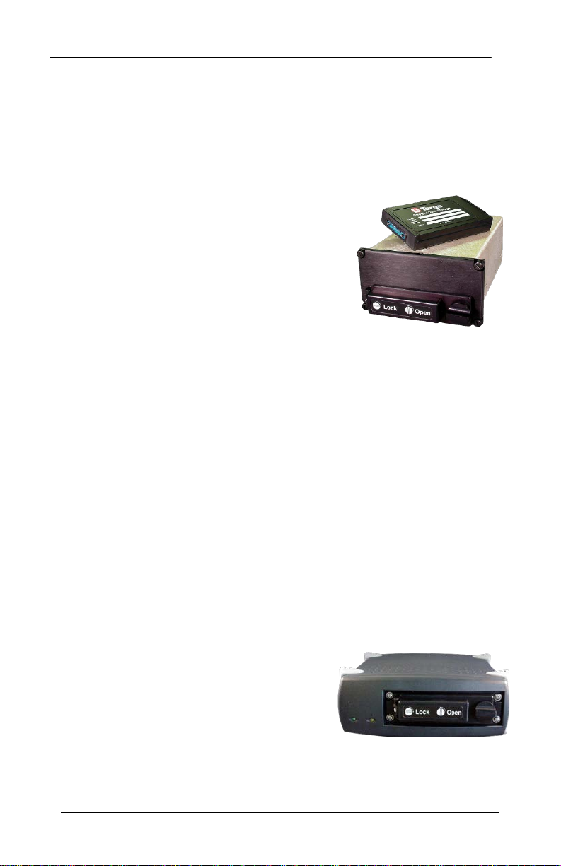
1.2 Data Transfer System Overview..........................................................................1
1.3 Model Numbers....................................................................................................2
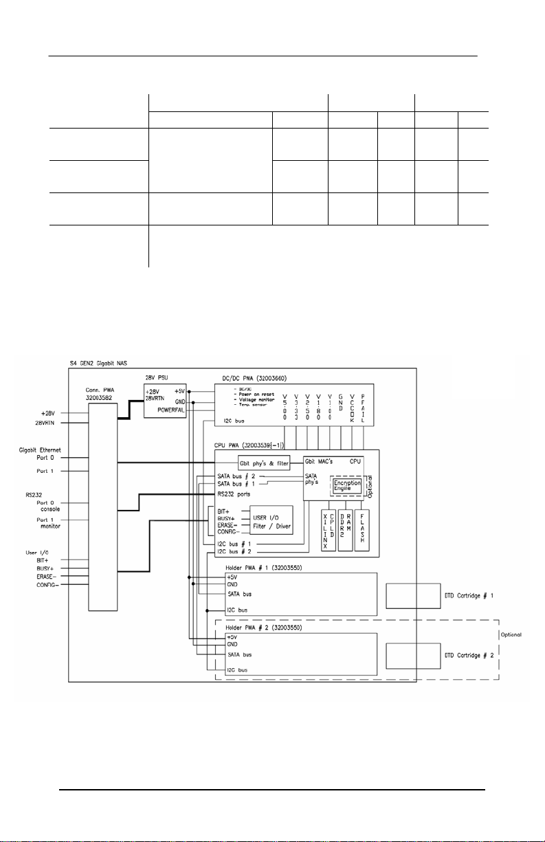
1.4 DTU Architecture..................................................................................................2
2. Specifications...........................................................................................................3
2.1 DTU and GSU Ethernet Interface........................................................................3
2.2 Data Transfer Unit................................................................................................3
2.3 Ground Station Unit .............................................................................................4
2.4 Data Transfer Device...........................................................................................4
2.5 Environmental Conditions....................................................................................5
2.5.1 Data Transfer Unit (DTU) and Data Transfer Device (DTD.........................5
2.5.2 Ground Station Unit (GSU)...........................................................................5
2.6 Interconnections...................................................................................................6
2.6.1 DTU J2 - Ethernet Connector Pinout..........................................................6
2.6.2 DTU J1 - Power & Auxiliary Signal Connector Pinout................................7
2.6.3 DTU and GSU - Auxiliary Input / Output Signal Functions.........................7
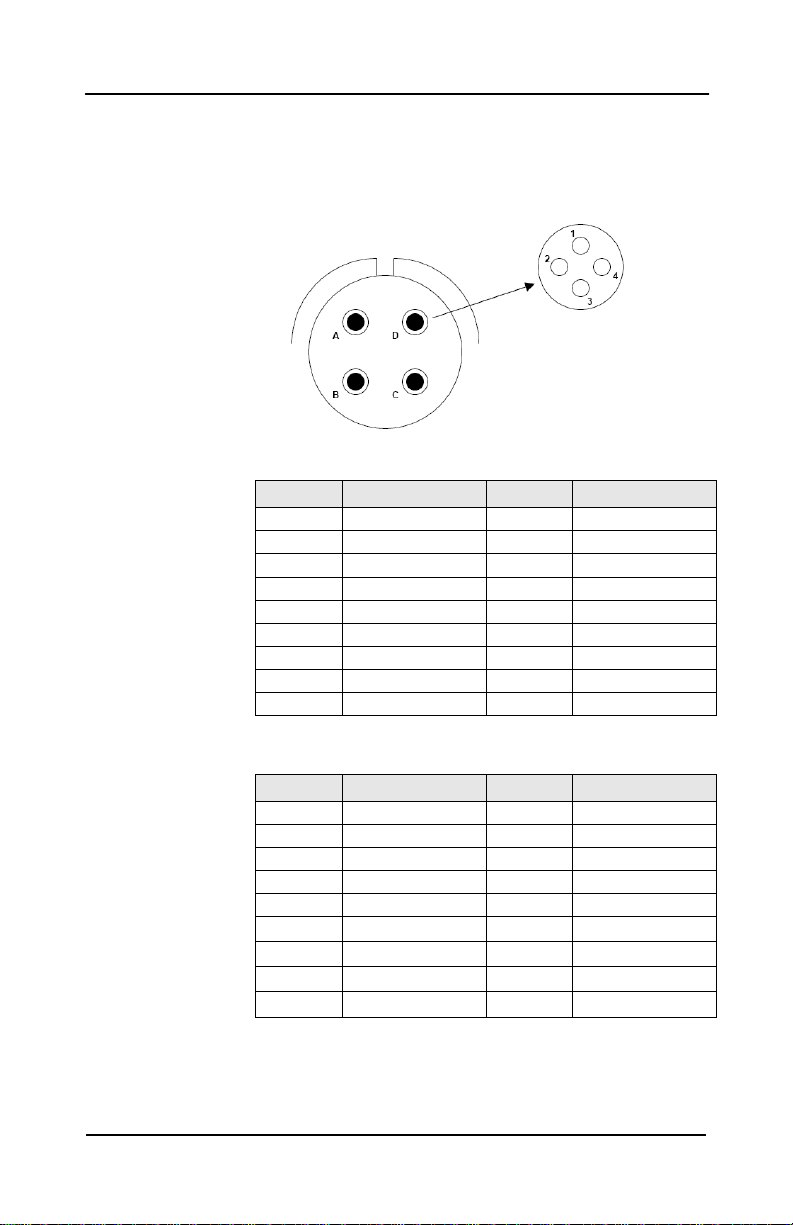
2.6.4 GSU Connector Pinout................................................................................8
2.6.5 DTD Connector Pinout.................................................................................9
2.7 Data Transfer System Reliability Performance...................................................9
2.8 Maintainability/Logistics Support.......................................................................10
3. Targa NAS DTU Operations – Overview ..............................................................10
3.1 DTD Use and Handling......................................................................................10
3.2Opening the DTD Access Door – DTD protection ............................................10
3.3 DTD NAS Partition File Structures ....................................................................11
3.4 DTD Write Protect..............................................................................................11
3.5 DTD Data Reliability...........................................................................................11
3.6 Power Fail ..........................................................................................................12
3.7 Security Erase....................................................................................................12
3.8 Monitoring DTU Output Messages....................................................................12
3.9 Dual DTD Data Transfer Unit ............................................................................12
4. Unit Configuration and Network Controls..............................................................13
4.1 User Configuration Utility...................................................................................13
4.1.1 DTU Configuration Control Panel ..............................................................13
4.1.2 Configuration Utility -Data Updates.........................................................13
4.2 DTU – Reboot Page...........................................................................................13
4.3 DTU-INFO Page.................................................................................................14
4.4 DTU Configuration Page....................................................................................15
4.5 DTU Network Configuration Page.....................................................................17
4.5.1 DTU Operation Mode.................................................................................18
4.5.2 Network Services........................................................................................19
4.5.3 Bridged Mode .............................................................................................22
4.6 DTU User Management Page...........................................................................23
4.7 DTD-INFO Page.................................................................................................24
4.7.1 Setup DTD Page.........................................................................................24
4.7.2 Setup Encryption Partition..........................................................................27
4.8 DTU Save and Restore......................................................................................27
5. Warranty & Repair.................................................................................................28
iii

Targa Systems Division
S4 Ethernet NAS DTS Installation Guide 32003272-1 Rev 5
Figure 1 DTU Architecture................................................................................................2
Figure 2 Ethernet Quadrax Connector Pin Orientation....................................................6
Appendix
A FTP Site Command..........................................................................................29
B DTD Sanitize / Secure Erase Algorithms........................................................ 40
C Encryption Overview & implementation .........................................................41
D DHCP Control File “dnsmasq.conf” ................................................................47
E DTD MTBF Data .............................................................................................48
F Network Data Capture Function .....................................................................49
G USB & SATA – DTD Erase / Sanitize .............................................................51
iv

Targa Systems Division
S4 Ethernet NAS DTS Installation Guide 32003272-1 Rev 5
1. Introduction
1.1 Scope
This document describes the installation and operational features of Targa Series 4
2nd generation Gb Ethernet Network Attached Storage (NAS) Data Transfer System.
1.2 Data Transfer System Overview
Targa Systems Series 4 NAS Data Transfer System has three (3) components:
DTU - Data Transfer Unit
DTD - Data Transfer Device
GSU - Ground Support Unit
DTU - Data Transfer Unit
Targa System’s Series 4 Ethernet DTU is a rugged, field
deployed unit providing dual 10/100/1000 Mbps
Ethernet network interconnections as well as the
electrical and mechanical infrastructure support for
the removable Data Transfer Device.
The DTU, based on the ARINC CDU style, (DZUS rail
mount) form factor is equipped with an RTCA-DO-
160C, Cat Z compliant 28VDC power supply and two rear
panel mount, MIL-C-38999 connectors; J1 for +28Vdc power and additional auxiliary
control and status signals; J2 for the dual Ethernet ports.
The DTU front panel accommodates four (4) DZUS ¼ turn fasteners and the DTD
access door. The access door is opened by simply rotating the ¼ turn door latch
counter-clockwise. This action releases the door lock mechanism and as the door is
opened, an optical sensor is tripped and the DTU executes an orderly power
shutdown of the network links, flushing cached data to the DTD and then removing
power from the DTD. This is an important feature to meet explosive atmosphere
requirements and to avoid data corruption due to operator actions during data write
operations. Once the door is open, the DTD is inserted through the front panel
aperture and gentlypushed into place. When closed, the door is locked by simply
rotating the latch clockwise.
DTD - Data Transfer Device
The Targa Systems Series 4 SATA Data Transfer Device (DTD) is a rugged
removable data storage unit containing a solid state 2.5” FLASH SATA disk enclosed
in a machined aluminium case with a high reliability, low insertion/removal force
connector. The S4 SATA DTD is designed with a flange on one side to prevent
improper insertion into the Data Transfer Unit (DTU) receptacle, or insertion into
other Targa Systems Series 4 Data Transfer Units that support SCSI or ATA type
Data Transfer Devices.
When the DTD is inserted into either a Data Transfer Unit (DTU) or a Ground
Support Unit (GSU), an optical sensor is used to detect the presence or absence of a
reflective label on the end plate. When reflected light is detected, the DTD is
mounted by the DTU / GSU as a read only device.
GSU - Ground Support Unit
The Series 4 GSU is a desktop, office grade unit
providing 10/100/1000 Mbps Ethernet network
interconnections to ground based data
preparation/retrieval computer systems as well as
electrical and mechanical support for the
removable Data Transfer device. The GSU front
face is designed with a keyway corresponding to the SATA DTD flange to ensure
that only the correct DTD type can be inserted and that the DTD is inserted in the
proper orientation. Data can be transferred to/from the DTD when inserted into the
GSU using widely supported file transfer protocols such as TFTP, FTP and NFS or
using the iSCSI block I/O protocol.
1

Targa Systems Division
S4 Ethernet NAS DTS Installation Guide 32003272-1 Rev 5
1.3 Model Numbers
Model
Description
DTD Support
Power
Unit Description
Encryption
Single
Dual
28Vdc
AC
DTU40SA-50A-2
Flight Unit - Panel Mount
-
√
-
√
-
DTU40SA-50A-2e
√
√
√
DTU40SA-52A-2
-
√
√
DTU40SA-52A-2e
√
√
√
GSU49/SA-50A-0
Ground Unit - Desktop
-
√
-
-
√
GSU49/SA-50A-0e
√
√
-
-
√
DTD40/SAn-ccc-2 SATA Flash Disk - Data Transfer Device
SAn – Flash disk type
Capacity where ccc = unformatted capacity in GBytes
1.4 DTU Architecture
Series 4 GEN2 DTU System Architecture is shown below:
Figure 1
DTU System Architecture
2

Targa Systems Division
S4 Ethernet NAS DTS Installation Guide 32003272-1 Rev 5
2. Specifications
2.1 DTU and GSU Ethernet Interface
Ethernet Compliance dual port auto sensing: 10/100/1000 Mbps
Address Protocol IPv4
Transport Protocol TCP, UDP
Application ProtocolTFTP, FTP, NFS, SMB/CIFS (Samba), iSCSI, DHCP,
HTTP
IEEE Physical Address 00:11:1B:xx:xx:xx
OUI for L-3 Targa 00:11:1B
Performance - varies with SATA disk type and test conditions, data transfer rates
presented below are nominal. Contact Targa for more detailed
performance capabilities
Data Reads 50 MBytes/sec - average data transfer rate FTP
Data Writes 30 MBytes/sec - average data transfer rate FTP
Startup Time 20 seconds (nominal – for the DTD to be mounted and be
available for user access)
2.2 Data Transfer Unit
Physical Characteristics
Single DTD Dual DTD
Mounting
DZUS rail mount per MS25221C
K=8 K=12
Unit Case Size
2.9"h x 5"w x 9.5"d
4.4"h x 5"w x 9.5"d
Front Panel
3.0"h x 5.75"w x .3”d
4.5"h x 5.75"w x .3”d
Weight
2.3 Kg
3.0 Kg
Max Power: 28Vdc
15 w
25 w
Inrush Current Nominal
3.5 A for 30msec
4 A for 60msec
Cooling
Passive, free air convection
Outline Drawing
www.targasystems.com/s4-2002.htm
Input Power - 28 Vdc
See Section 3.6 for details on power fail detection and operations.
RTCA/DO160C Cat Z with 50 msec holdup capability
Normal Operation 22 - 29.5 Vdc (18 emergency low)
Ripple 2v rms
Interrupt 1 sec (Unit Reset)
Surge 50Vdc 50ms / 12vdc 30ms
Under voltage 10v 15sec, with unit reset
Abnormal Operation 20 - 32.2 Vdc
Surge 80Vdc 100ms / 48Vdc 1sec
Under voltage 12v 7sec, with unit reset
Over Voltage: For voltages exceeding 40V and less than 80V, a limiting circuit
is modulated in order to maintain the input voltage to the module
within acceptable limits. The over voltage surge protection is
limited to 80V for 100ms, for surges exceeding that voltage and
duration, damage may occur to the unit.
Over Current 7A fusible resistor
3

Targa Systems Division
S4 Ethernet NAS DTS Installation Guide 32003272-1 Rev 5
Ethernet Connector Amphenol TVP00RGQF-21-75S
MIL-DTL-38999, wall mount, shell size 21
with four 21-33385-51 Quadrax sockets
Material: Electroless nickel finish
Mate Amphenol TV06RGQF21-75P
or CTV06RGQF-21-75P
MIL-DTL-38999, straight plug, shell size 21
with four 21-33384-51 Quadrax pin. (C prefix for
composite shell)
For use with: Tensolite NF24Q100 Netflight cable
Pinout Refer to section 2.6
Power & Aux Connector D38999/20MC35PN
MIL-C-38999 Series 3, Rear mount, 22 pin contacts
Mate D38999/26FC35SN
Pinout Refer to Section 2.6
2.3 Ground Station Unit
Case Size 3.4”h x 9"w x 12"d approx.
Weight 3.2 Kg max
Input Power 96 - 276 VAC, 50 - 60 Hz @ 25 watts
Internal fan 22cfm (60 x 60mm ball bearing)
Ethernet Connectors 2 x RJ-45
Pinout Refer to Section 2.6
Aux Connector 1 DB9F Console Port
2 DB9M Monitor Port
Pinout Refer to Section 2.6
2.4 Data Transfer Device
Case Size 3”w x 4.8”l x 0.9”h
Finish Black epoxy paint
Weight < 500 g
Connector Hypertronics KA17/127BEFD21TAH
Pinout Refer to Section 2.6
4

Targa Systems Division
S4 Ethernet NAS DTS Installation Guide 32003272-1 Rev 5
2.5 Environmental Conditions
2.5.1 Data Transfer Unit (DTU) and Data Transfer Device (DTD
Temperature
Operating -40°C to +71°C MIL-STD-810E, Method 501.3
Storage -55°C to +85°C MIL-STD-810E, Method 502.3
Altitude 50,000 ft MIL-STD-810E, Method 500.3
Humidity 10-100% Condensing RTCA/DO–160D, Sec 6, Cat. B
Shock Operating 20g, 9 ms, ½ sine
MIL-STD-810E Method 516.4
Crash Hazard 40g, 9 ms, ½ sine - operating
MIL-STD-810E Method 516.4
Vibration Dzus Mount PSD 0.04g2/Hz, 5-2000 Hz
MIL-STD-810E, Method 514.4, Cat 10
Waterproofness RTCA/DO–160D, Sec. 10, Cat. W
Sand & Dust RTCA/DO–160D, Sec. 12, Cat. D
Fungus RTCA/DO–160D, Sec. 13, Cat. F
Salt Spray RTCA/DO–160D, Sec. 14, Cat. S
2.5.2 Ground Station Unit (GSU)
Temperature 10°C to + 50°C
Humidity 10 - 85% (non condensing)
Altitude -1000 to 10,000 ft
5

Targa Systems Division
S4 Ethernet NAS DTS Installation Guide 32003272-1 Rev 5
2.6 Interconnections
2.6.1 DTU J2 - Ethernet Connector Pinout
Each of the four Quadrax sockets (A,B,C,D) has 4 contacts (1,2,3,4) as
shown below – for a total of 16 contacts:
For 1000 Base-T
(Gb ethernet)
For 10/100 Base-T
NOTE: When using the 10/100 Base-T wiring, the NAS unit must first be re-
configured to set Link speed to 10/100. The NAS unit default
configuration is to negotiate for Gbit ethernet which cannot be done with
only 4 wires. Once re-configured a 10/100 cable can be used.
Pin
Signal
Pin
Signal
A1
Port1 a+
D1
Port1 c+
A2
Port1 b+
D2
Port1 d+
A3
Port1 a -
D3 Port1 c-
A4
Port1 b -
D4
Port1 d -
B1
Port2 a+
C1
Port2 c+
B2
Port2 b+
C2
Port2 d+
B3
Port2 a -
C3
Port2 c -
B4
Port2 b -
C4
Port2 d -
Pin
Signal
Pin
Signal
A1
Port1 Tx+
D1
n/c
A2
Port1 Rx+
D2
n/c
A3
Port1 Tx-
D3
n/c
A4
Port1 Rx-
D4
n/c
B1
Port2 Tx+
C1
n/c
B2 Port2 Rx+ C2
n/c
B3 Port2 Tx- C3
n/c
B4
Port2 Rx-
C4
n/c
J2 Connector
with 4 Quadrax
Sockets
Quadrax contact
arrangement
6

Targa Systems Division
S4 Ethernet NAS DTS Installation Guide 32003272-1 Rev 5
2.6.2 DTU J1 - Power & Auxiliary Signal Connector Pinout
Signal Pin Description
+28 VDC
+28 RTN
12
13
Power Supply Input
Power Supply Return
COM1 RX
COM1 TX
Reserved
Secure_Erase-
BUSY+
UNIT_OK+
Config_Enable-
COM2 TX
2
3
4
5
8
9
16
17
RS232 Receive of Console Port
RS232 Transmit of Console Port
Reserved Input
Security Erase Input, LVTTL active low
DTU Busy Indicator, LVTTL active high
PBIT Passed Indicator, LVTTL active high
DTU Configuration Enable, LVTTL active low
RS232 Transmit – DTU Monitor Port
CaseGnd
1, 11, 14, 20,21
SignalGnd
6, 7, 10, 15, 18, 19, 22
2.6.3 DTU and GSU - Auxiliary Input / Output Signal Functions
Inputs: (1,3)
Config_Enable- When pulled to signal ground
- enables DTU configuration mode. See Section 4.1
- status is determined at power-on.
Secure_Erase- When pulled to signal ground activates the DTD Secure
Erase function. See Section 4.4
Outputs (2,3)
BUSY+ Indicates data transfers in process to the DTD
UNIT_OK+ Indicates DTU has passed Power-On BIT
Notes: 1. Inputs are internallypulled high (10 Kohm)
2. Outputs are not capable of direct LED drive
3. LVTTL 3.3Vdc Voh min 2.4V @ -4ma
Vol max 0.4V @ 4ma
Vil max 0.7v
4. GSU is shipped with a DB-9 config-plug Targa PN 32003425
5. Console Port setup: 115KB 8bit, no parity; 1 stop bit
7

Targa Systems Division
S4 Ethernet NAS DTS Installation Guide 32003272-1 Rev 5
2.6.4 GSU Connector Pinout
10/100/1000 Mbps Ethernet - RJ45
Signal Pin Gb Ethernet
Signal Description
10/100
Signal Description
BI_DA+
BI_DA -
BI_DB+
BI_DC+
BI_DC -
BI_DB -
BI_DD+
BI_DD -
1
2
3
4
5
6
7
8
Bi-directional pair A+
Bi-directional pair A-
Bi-directional pair B+
Bi-directional pair C+
Bi-directional pair C-
Bi-directional pair B-
Bi-directional pair D+
Bi-directional pair D-
Tx+
Tx-
Rx+
-
-
Rx-
-
-
Console Port DB9F
Signal Pin Signal Description
Com1 Tx
Com1 Rx
Gnd
DCD-RTS-CTS
DTR-DSR
Com2 Tx
2
3
5
1-7-8
4-6
9
Console Port - RS232 Transmit
Console Port - RS232 Receive
Ground
RS232 DCD-RTS-CTS Loopback
RS232 DTR-DSR Loopback
Com2 – RS232 Transmit
Auxiliary Functions DB9M
Signal Pin Signal Description
Config_Enable-
Secure_Erase-
Reserved
BUSY+
UNIT_OK+
Gnd
1
5
6
8
9
2,3,4,7
Configuration Enable, TTL active low
Security Erase Input, TTL active low
Reserved Input
DTU Busy Indicator, TTL active high
BIT Passed Indicator, TTL active high
Ground
Port 1 Port2
8

Targa Systems Division
S4 Ethernet NAS DTS Installation Guide 32003272-1 Rev 5
2.6.5 DTD Connector Pinout
Pin
Signal
Signal
Pin
1
SATA RX+
Gnd
2
3 SATA RX- Gnd 4
5
SATA TX-
Gnd
6
7
SATA TX+
Gnd
8
9
Gnd
Reserved
10
11
Reserved
Reserved
12
13 Gnd Gnd 14
15
DTD Installed (Gnd)
+5Vdc
16
17
+5Vdc
2.7 Data Transfer System Reliability Performance
Series 4 - Data Transfer Devices
DTD40SAx - ccc – 2
Refer to Appendix E
Series 4 Data Transfer Unit
DTU40SA-50A-2
(Single DTD)
DTU40SA-52A-2
(Dual DTD)
Environment
MTBF (hrs)
MTBF (hrs)
GB 35°C
151,676
144,113
GM 35°C
30,335
28,823
AIC 35°C
45,503
43,234
AUC 45°C
13,651
12,970
AIF 35°C
30,335
28,830
AUF 45°C
13,651
12.970
ARW 35°C
15,168
14,411
9

Targa Systems Division
S4 Ethernet NAS DTS Installation Guide 32003272-1 Rev 5
2.8 Maintainability/Logistics Support
Targa recommends that all of the Series 4 NAS components be designated as
LRU with return to Targa Systems for repair.
Maintenance activities DTU – none
GSU – none
DTD – inspect DTD connector for damage or obstructions
Unscheduled Service Time to replace DTU estimated @ < 15 minutes
Test Equipment a. Industry Standard PC with Ethernet Interface
b. DTU J1 & J2 Test cables & 28Vdc power source
BIT Features Basic unit health check performed via Power Up BIT
Tested elements: CPU; Memory and Ethernet controller
Keying a. DTU rear connectors are keyed to ensure proper
installation.
b. DTD case is keyed to ensure proper installation through
the DTU & GSU faceplate cutouts.
3. Targa NAS DTU Operations – Overview
Targa Systems Ethernet NAS DTU is a dedicated data storage device intended to
be connected directly to a network to provide centralized data access and storage
via a removable Data Transfer Device containing a SATA FLASH disk . The
following is a brief overview of some of the systems operational features.
3.1 DTD Use and Handling
Targa's Ethernet DTU/GSU is equipped with a door sensor to detect door
open/close status. Upon detection of a door open event the DTU/GSU will
execute the Door Open algorithms as outlined below.
To install the DTD, open the DTU/GSU access door and slide the DTD through the
faceplate slot until it is fully engaged in the receptacle.
To remove the DTD, open the DTU/GSU access door, firmly grip the exposed end
of the DTD and pull to extract.
Note: The DTD to DTU interconnect is via a low insertion force connector rated
over 100,000 insertion /removal cycles. The user must, however, ensure
that no foreign matter is trapped in the DTD connector before insertion into
the DTU/GSU to prevent damage to the inter-connecting pins.
3.2 Opening the DTD Access Door – DTD protection
Targa Systems DTU and GSU products are designed to protect against data file
corruption if the access door is opened while there is disk activity.The DTU and
GSU products are equipped with protective circuitry to detect the DTD access door
being open, DTD installed as well as a DTD power on/off control. These features
are used to activate the DTD shutdown process for data integrityas well as
meeting explosive atmosphere requirements.
10

Targa Systems Division
S4 Ethernet NAS DTS Installation Guide 32003272-1 Rev 5
When a Door Open event occurs, the following sequence is performed:
- FTP and NFS processes for that DTD are terminated
- DTD filesystem is unmounted
- Write pending ext4 file system journal to DTD
- Turn DTD power Off
When the Door is closed, the following sequence occurs:
- DTD is initialized
- If a valid file system is detected – the DTD is mounted
- If reflective label detected – DTD is mounted Read only
NOTE: Depending upon unit activity, it may take the DTU several seconds to
complete all pending data writes to the DTD. Users should wait
approximately 3-5 seconds after the door is opened before removing the
DTD.
3.3 DTD NAS Partition File Structures
Data is stored on DTD NAS partitions using the ext4 filesystem (extended
filesystem version 4) with journaling capabilities. A journaling filesystem keeps a
log of filesystem transactions and in the event of a major uncontrolled event, such
as a power failure, the journal will be played back during the next disk mount
process and any filesystem inconsistencies automatically corrected.
This does not mean that data sent to the DTU immediatelyprior to a power failure
cannot be lost, but it does mean that the existing data and file structures will not be
corrupted.
Due to the overheads associated with the journaling filesystem, Targa
recommends that the DTD be periodicallyreformatted using the DTU Configuration
utility.
3.4 DTD Write Protect
The DTD can be write protected by installing one of
the reflective write protect labels (Targa P/N
32003256) supplied with the DTD. When a write protect
label is detected by the DTU or GSU the DTD will be mounted
as a read only device.
3.5 DTD Data Reliability
The Data Transfer Device uses a sophisticated SATA FLASH disk as the data
storage medium providing enhanced data reliability via the following mechanisms:
· All erase/write operations are performed in a closed loop operation to verify
data has been erased and programmed correctlywith the proper voltage
margins.
· Data is checked with a powerful Error Correction Code (ECC) that offers a
high degree of data protection.
· Built in defect management with automatic sector reassignment based on
detected memory errors.
NOTE: DTDs are shipped from Targa
with an EXT3 partition for compatibility
with older systems. See 4.7.1 for
information on reformatting to EXT4
11

Targa Systems Division
S4 Ethernet NAS DTS Installation Guide 32003272-1 Rev 5
3.6 Power Fail
The DTU’s 28Vdc power supply features a power fail detection circuit along with a
50 millisecond holdup capability to support DTU operations during power
interruptions to ensure data integrity.
When a Power Fail is detected (< 17Vdc), the following sequence occurs:
Power Fail signal debounced, ignored if < 1ms
Ethernet File data transfers are suspended
All DTD I/O operations are suspended.
If the input power recovers within the 50msec holdup period, the DTU will resume
normal operations.
In the event of an extended brown-out; when the input power recovers the DTU
will resume operations – as if there had been a door open/close sequence.
Any suspended I/O is written to the DTD
Network connections are reset
DTD(s) remounted
Note: The power fail feature is not supported bythe desktop GSU version.
3.7 Security Erase
The Targa Series 4 NAS Data Transfer System, supports both a hardware and
ethernet commanded means of sanitizing the Data Transfer Device.
Hardware: via the Secure_Erase- input
Refer to section 4.4 for details
Commanded via the FTP Site command dtdsanitize - see appendix A
via the HTTP Configuration / setup utility - see section 4.7
Note: Secure Erase will override Write Protect
3.8 Monitoring DTU Output Messages
The Targa NAS DTU is equipped with an RS-232 output monitor port (COM2) that
can be used to assist users during systems integration, or to provide additional
error/warning messages as part of systems operations. Refer to section 4.4 for
details on COM2 log Verbosity.
3.9 Dual DTD Data Transfer Unit
The Dual DTD Data Transfer Unit
supports two independent removable
FLASH disks. If the door is opened to
access one disk it does does not
interrupt the 2nd disk as long as 2nd
disk access door remains closed.
NAS mount points are:
DTD #1: /dtd/a/part1 (upper door)
DTD #2: /dtd/b/part1 (lower door)
12

Targa Systems Division
S4 Ethernet NAS DTS Installation Guide 32003272-1 Rev 5
4. Unit Configuration and Network Controls
4.1 User Configuration Utility
The DTU User Configuration Utility can be used to review and setup the Targa
DTU operational parameters.
To access the DTU / GSU embedded User Configuration Utility:
-Connect the DTU / GSU to the network and from your web browser go the
DTU Configuration IP Address http://192.168.2.104
-Login with admin User ID and Password (section 4.6). When logged in the
DTU Configuration Control Panel and DTU INFO page will be displayed.
To update DTU / GSU configuration data using this utility
- the “Config Enable-“ input must be connected to ground. If not installed
current configuration data is displayed, but cannot be changed.
4.1.1 DTU Configuration Control Panel
Select the appropriate DTU page link to access each of the Targa DTU
configuration pages. Refer to the individual configuration page in this section for
details on page controls and supported features.
4.1.2 Configuration Utility -Data Updates
After changing or adding new DTU configuration data, the revised configuration
data must be “Submitted” for the associated DTU configuration data files to be
updated. When all of the changes have been made the Targa DTU must then be
rebooted for the new configuration data to take effect.
Each DTU Configuration page, that provides access to user controlled parameters,
will display the “Submit Changes” button:
Submit Changes: Used to submit the data as entered on the page into the
DTU configuration files. When the configuration files have been
updated, all DTU subsequent configuration pages will display the
following message, until a DTU reboot or power cycle has been
performed:
The DTU's configuration has changed.
A reboot is required for the changes to take effect
To initiate the DTU reboot – select “DTU Reboot” on the DTU
Control Panel
Reset Clears the changes as entered on this page and reverts to the
current settings.
4.2 DTU – Reboot Page
Click “Yes” to confirm DTU reboot.
The DTU will reboot in approximately 30 seconds and will re-
display the DTU-info page when the reboot process had completed
13

Targa Systems Division
S4 Ethernet NAS DTS Installation Guide 32003272-1 Rev 5
4.3 DTU-INFO Page
Displays Basic DTU information:
Model#: Targa DTU Model #
Serial#: DTU serial number YYMMxxxxxx
YYMM is the DTU date of
manufacture
xxxxxx is the DTU MAC
address
Firmware: DTU firmware version and part
number
Config Mode: Must be enabled to update
unit configuration data.
See section 2.6.3
System Time: Current time within the DTU
At power up defaults to 00:00:00 January 1, 1970 GMT
DTU time can be set via 2 mechanisms
- FTP Site Command “SETTIME”
- rdate server -time is requested at power-on (refer to the DTU
Network configuration page for details)
Uptime: Length of time that the DTU has been operational.
Uptime can be used to determine if the DTU has experienced a
power failure recovery since it was last accessed (ie: if your current
directory has changed back to the default mount point due to
system reboot)
Load Avg: Measure of average DTU CPU utilization use as a % over time for
the past: 1 min, 5 min, 15 min
Load Avg can be used as a reference, during test and integration to
determine if there are sufficient resources available to handle more
client sessions or file transfers. Note: 1.0 = 100% and loads > 1.0
are normal.
Power State: Status of input power:
Good - input power within range
Power-fail - input power is < 17Vdc and DTU is operating in
power-fail protection mode.
Refer to Section 3.6 for more details.
DTD State Status of DTU access door as well as DTD #1 [and DTD #2 ]
Door Open
Door Closed, DTD Not Present
Door Closed, DTD Present
Door Closed, DTD Present, Write Protected
14

Targa Systems Division
S4 Ethernet NAS DTS Installation Guide 32003272-1 Rev 5
4.4 DTU Configuration Page
Displays Targa DTU identification
data and provides access to the
DTU features configuration
parameters.
DTU Identification:
Model#: Targa DTU Model
#
Serial#: DTU serial
number
Firmware: DTU firmware
version and part
number
DTU Features
Erase Input / Erase Algorithm:
The Targa DTU supports a
remote sourced Erase input
signal used to activate a user
specified DTD Security Erase
algorithm. Refer to Appendix B for details on the supported Sanitize / Secure
Erase algorithms.
If the Erase input is disabled, the Erase Algorithm entry is not applicable.
Factory default is disabled.
Erase Input Signal: (Secure_Erase- refer to 2.6.3 & 3.7)
Active low input signal. Signal must transition from Off state (logic high) to On
state (logic low) and be logic low for a minimum of 300msec for DTU to
activate erase. If the signal is detected as logic low at power up or at door
closure the signal is disqualified until it returns to the logic high state (for a
minimum 300msec). If the Erase Input feature is disabled the signal is not
monitored.
Refer to the FTP Site command “dtdsanitize” for details on the ethernet
commanded DTD Secure Erase.
Enable Temp Alerts: Enabled Disabled
The DTU is equipped with an on-board temperature sensor that can be used
to monitor the internal temperature. The temperature monitoring process can
also, when enabled, issue an alert at a user specified temperature. Refer to
the FTP Site command section for details on how to read unit temperature
and detect a temperature alert.
Factory default is disabled.
Temperature Alert at: Default: 90ºC Input range: 80ºC to 100ºC
Temperature Alert value is used only when Temp Alert is enabled
15

Targa Systems Division
S4 Ethernet NAS DTS Installation Guide 32003272-1 Rev 5
Firmware Upgrade
The Targa DTU firmware is field upgradeable using a DTD as the transport
mechanism.
To upgrade DTU firmware:
1. The DTU “Config Enable-” input must be connected to ground.
2. A DTD installed with the new firmware code stored in /dtd/a/part1 as:
targa-firmware.edtu if not modifying unit configuration
or targaconf-firmware.edtu restore factory default configuration
Note: If both files found: targa-firmware.edtu takes precedence
3. Firmware upgrade process must be enabled and the upgrade initiation
mechanism selected. The options are:
Disabled - firmware upgrade process disabled
On-boot - at DTU startup, the DTD will be read and if either of the
specified DTU firmware files are present, the DTU
firmware will be updated.
Manual - Update process will be initiated upon receipt of the FTP
Site “SITE UPDATEFIRM” command at which time, the
DTD will be read and if either of the specified DTU
firmware files are present, the DTU firmware will be
updated
On-boot, Manual– either update processes can be used
Notes: - The firmware update process can take anywhere from 3-5 minutes
and MUST BE monitored on the COM2 Log port. During the
update process a stream of “….” will be output and a completion
message issued. DO NOT POWER OFF UNTIL UPDATE IS
COMPLETE. Any Error Conditions encountered during the update
process are output on the COM2 Log port.
- Upon completion of the firmware update process the DTU will
reboot.
- If the targa-firmware.edtu file is used, then the DTU must be re-
booted a 2nd time for the existing configuration files to be transferred
into the new operational code space . If this is not done a DTU
unconfigured error will be reported in FTP Site “Healthcheck” and
DTU functionality may be compromised.
- To install previous firmware versions: Onlythe manual process will
support loading older firmware and only with the
targaconf-firmware.edtu file. This ensures synchronization of
configuration files to the operational code set.
- F/W 3.1.4 and onward - Factory default is now manual.
COM2 Log Verbosity
The Targa DTU provides an RS-232 system monitor port designated COM2.
COM2 Log output is: RS-232, 8bit ASCII, no parity, 1 stop bit at 115.2K BAUD
Select the messages output level:
Off - no message output
Low - Critical messages only
Medium - Warnings, Errors and Critical messages
High - all messages including debug messages
16
This manual suits for next models
6
Table of contents
Popular Storage manuals by other brands

Freecom
Freecom FC TapeWare AIT-250i FC specification

Copernicus
Copernicus Tech Tub2 Assembly guide

Lanner
Lanner HTCA-6310S user manual

SSI SCHAEFER
SSI SCHAEFER R 3000 Assembly instructions

IBM
IBM DS3500 Installation, user's, and maintenance guide

Apricorn
Apricorn Aegis Padlock A25-PL128 640GB Specifications