LA Fitness Runfit 99 User manual

RUNFIT 99
OWNER’S MANUAL

1
2011/11/7 V1.1+V1.0
Table of Contents
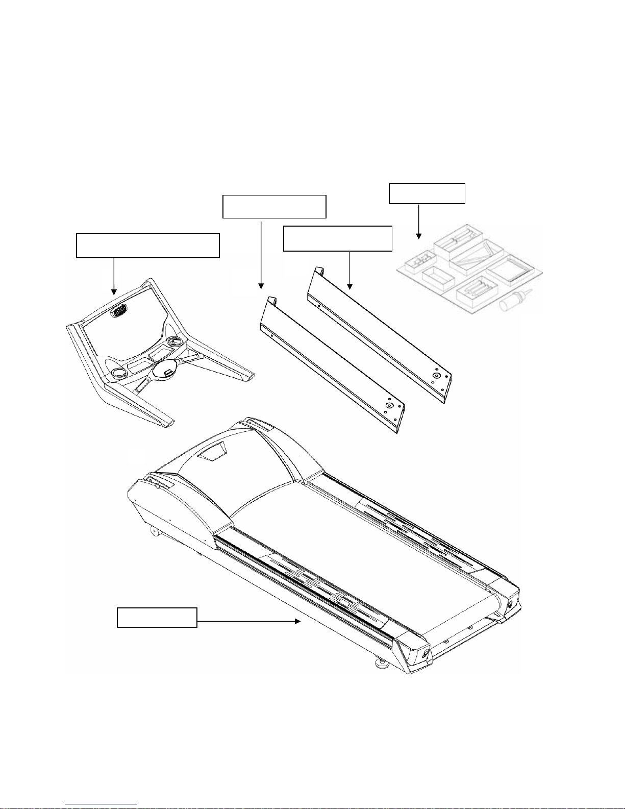
1 Components Check ......................................................................................................................................................2
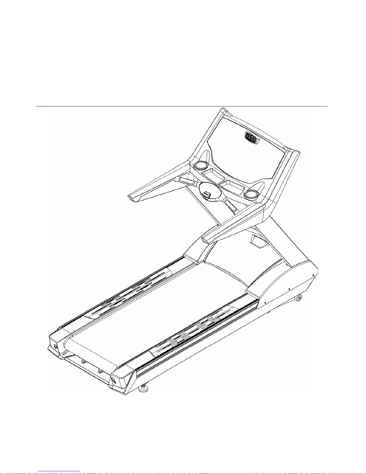
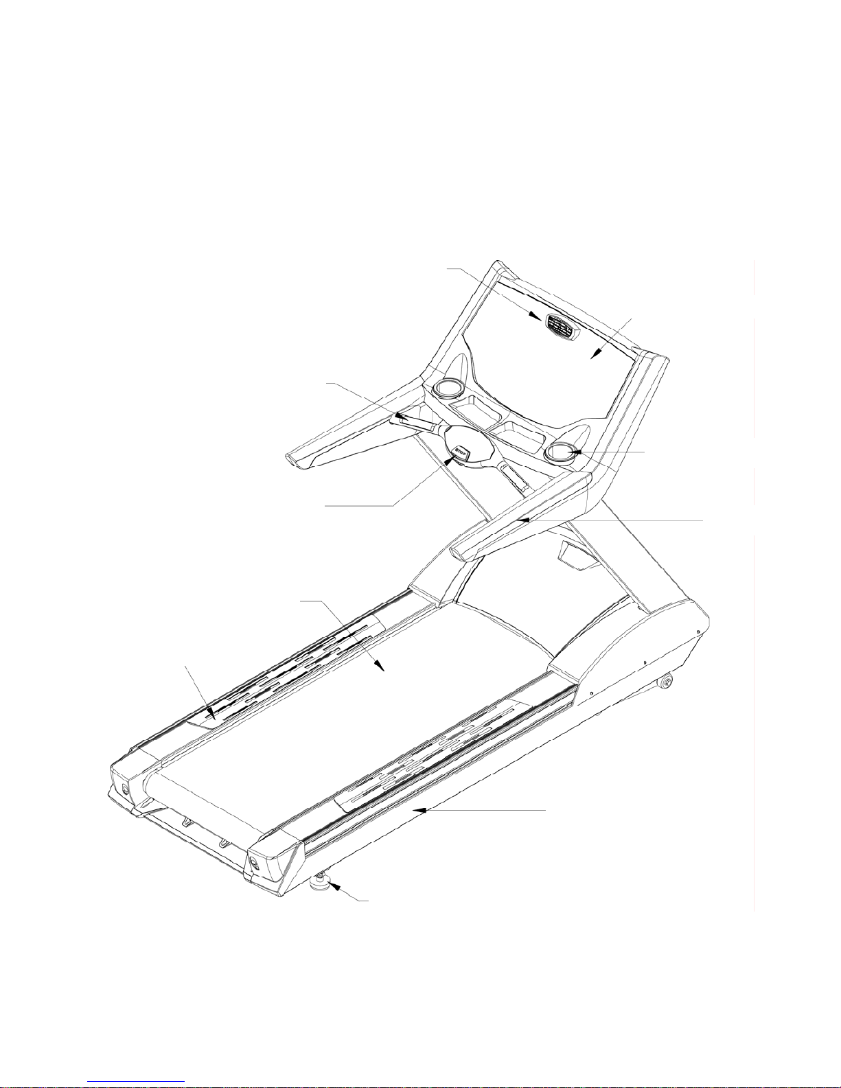
2 Overview Drawing.......................................................................................................................................................3
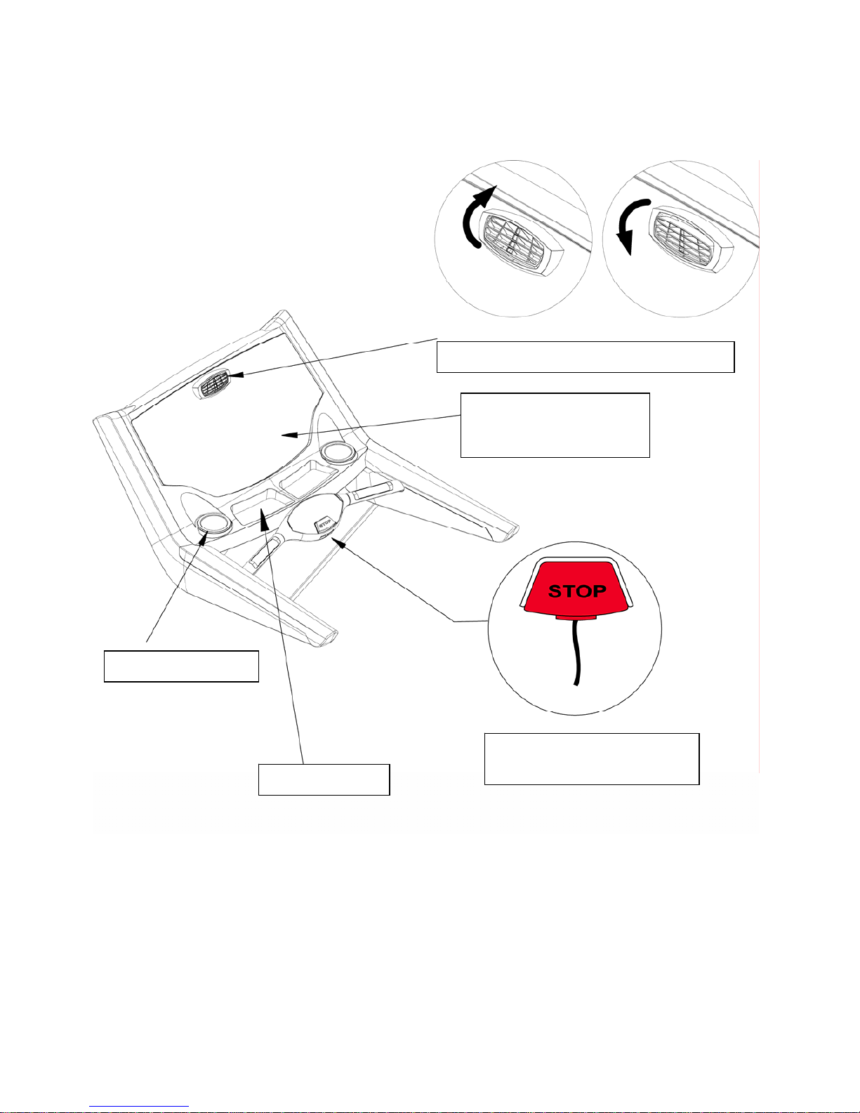
2-1 Computer Console..........................................................................................................................................4
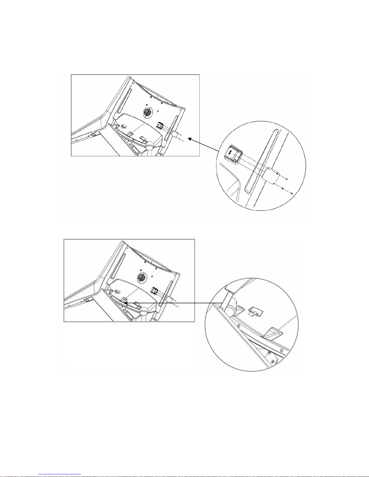
2-2 ISP Slot And C-SAFE Slot.............................................................................................................................5
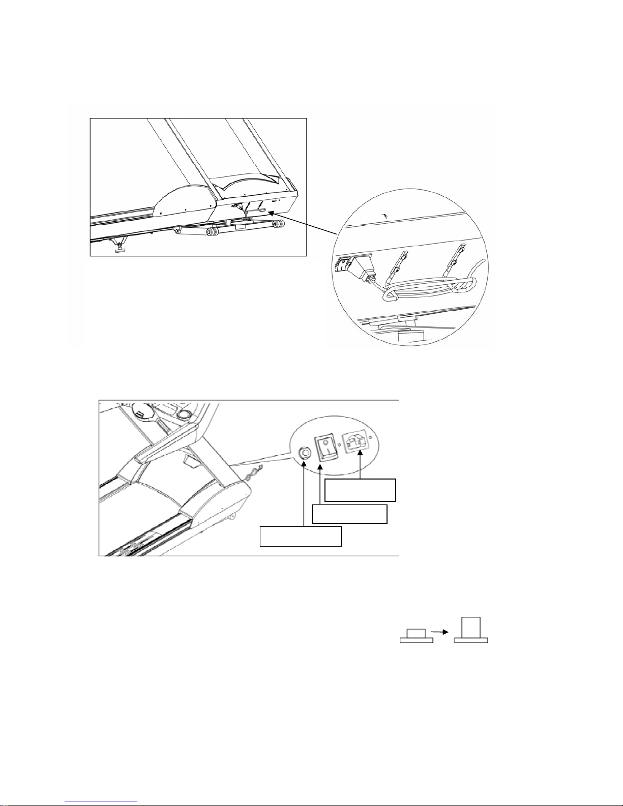
2-3 Wire Rod System And Power Switch.............................................................................................................6
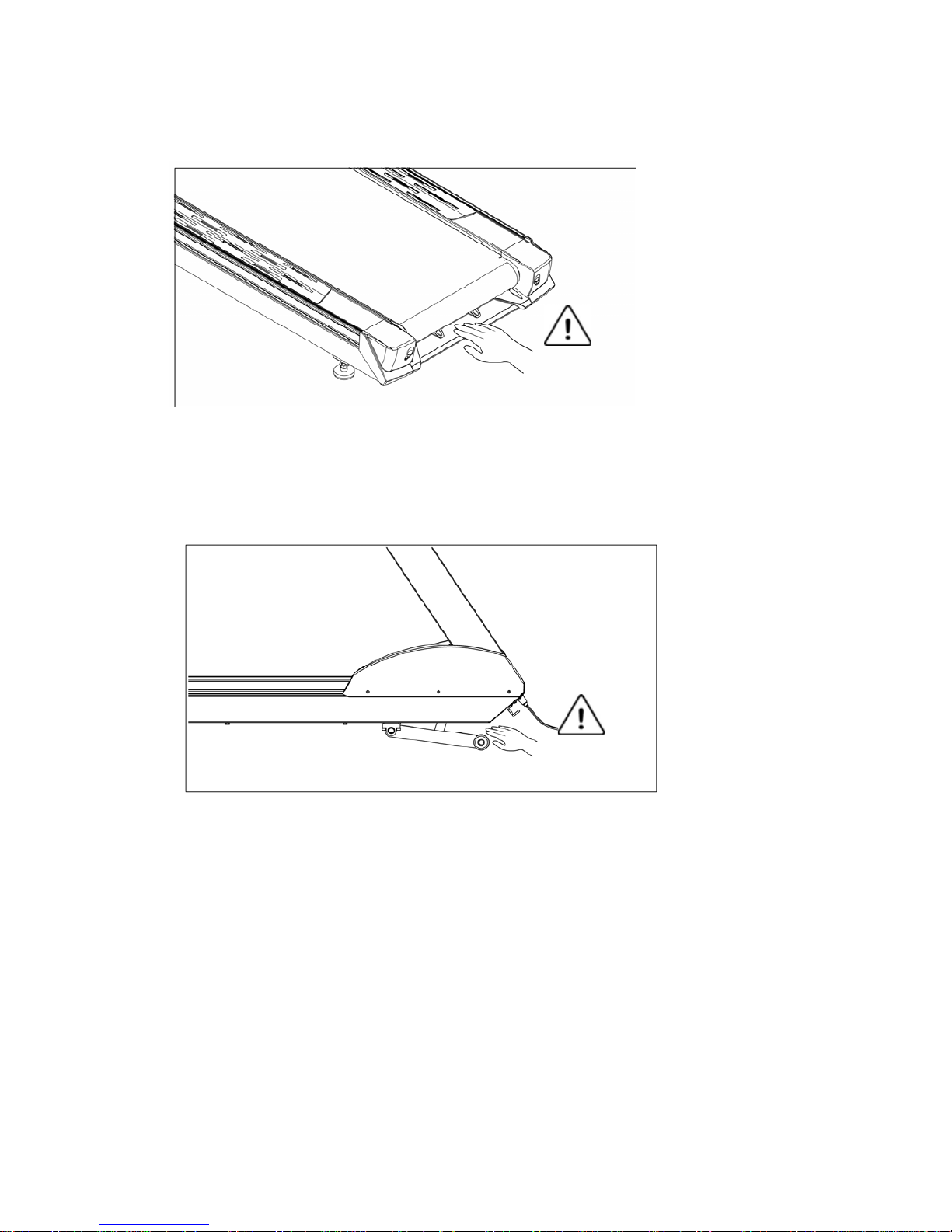
2-4 Running Belt And Side Incline Base..............................................................................................................7
3 Caution.........................................................................................................................................................................8
3-1 Important Safety Instructions .........................................................................................................................8
3-2 Electrical Power Requirement......................................................................................................................10
3-3 Adding SILICON .........................................................................................................................................11
3-4 ADD SILICONE..........................................................................................................................................12
3-5 Leveling Adjustment ....................................................................................................................................13
3-6 Power Switch ...............................................................................................................................................13
3-7 Centering The Belt .......................................................................................................................................14
3-8 Emergency Stop System...............................................................................................................................15
3-9 Fitness Networking ......................................................................................................................................17
4 Assembly Instructions................................................................................................................................................18
4-1 Pre-Assembly Check List.............................................................................................................................18
4-2 Assembly Steps.................................................................................................................................................20
5 Computer ...................................................................................................................................................................22
5-1 Computer Structure...........................................................................................................................................22
5-2 Bottle Holder and Utilities Trays ......................................................................................................................25
6 Heart Rate Zone Training...........................................................................................................................................26
6-1 Heart Rate Zone Training .................................................................................................................................26
6-2 Heart Rate Monitoring ......................................................................................................................................27
7 Programs ....................................................................................................................................................................28
8 ERROR CODE DISPLAY.........................................................................................................................................40

2
2011/11/7 V1.1+V1.0
1 Components Check
Please check the following parts carefully after opening the box. If there are any missing please contact
your sales agent.
Parts kit x1
Computer Console x1
Frame x1
Left Upright x1
Right Upright x1

3
2011/11/7 V1.1+V1.0
2 Overview Drawing
Touch sensor console
Fan Vent
Hand Pulse Set
Bottle Holder
Handrail
Emergency Key
Runnin
g
Belt
Anti Slip Pad
Frame
Adjustable Foot

4
2011/11/7 V1.1+V1.0
2-1Computer Console
Touch sensor console
See detailed instructions at
5-1 Computer Structure
Fan Adjust to change the wind direction.
Emergency Stop
Refer to 3-8 Emergency Stop
Utility Tray
Bottle Holder

5
2011/11/7 V1.1+V1.0
2-2ISP Slot And C-SAFE Slot
ISP Slot
In the event of an upgrade to the software is
necessary, this port will be used.
C-SAFE Slot
This treadmill can be connected to a
network by the RJ45 port on the back of
control board.

6
2011/11/7 V1.1+V1.0
2-3Wire Rod System And Power Switch
升降機構
Wire Rod System
Coil the extra power cord on this to tidy it up.
CAUTION !
Don’t carry the treadmill by this as it will bend.
Power Switch
Circuit Breaker
If the current goes over the rated value, it will reset automatically.
After 10 minutes, the pressure will go back to the preset value.
Power Socket
Pay attention to the voltage of the socket (110V or 220V).
Power Socket
Power Switch
Circuit Breaker
Automaticall
y
Rese
t

7
2011/11/7 V1.1+V1.0
2-4Running Belt And Side Incline Base
Running Belt
Keep hands away from the running belt while the treadmill is running. If
service needs to be done near this area, turn the treadmill off and unplug
the unit first.
Warning
Warning
Side Incline Base
Keep hands away from the front end of the treadmill and elevation arm. If
service needs to be done near this area, turn the treadmill off and unplug
the unit first.

8
2011/11/7 V1.1+V1.0
3 Caution
3-1Important Safety Instructions
Warning:
To reduce the risk of burn, fire, electric shock, or physical injury, please read the important
safety instructions and product information carefully before starting to use this product. The
owner of the treadmill should take on the responsibility to make sure that all the users can fully
understand the cautions and important safety instructions
• Before starting any exercise/fitness program you should consult with your healthcare professional.
• Please operate the treadmill according to this manual. Do not use any attachment or replacement part
not recommended in order to avoid accidents or injury.
• Put the treadmill on a flat floor; keep the area 2 meters (6 feet) behind the treadmill clear. Do not put
the treadmill in a position where circulation of air can be blocked. Ideally put a rubber mat under the
treadmill to prevent the floor or carpet from damage and to help to avoid dust getting into the
treadmill.
• When choosing the position of the treadmill, please be sure there is an outlet with a dedicated circuit
near that position.
• Put the treadmill indoors to keep it free from moisture and dust. Do not use near pools or other areas
of high humidity.
• Do not operate where aerosol (spray) products are being used or where oxygen is thin.
• Do not let children under 12 years old use the treadmill without supervision. Close supervision is
necessary when used by invalids, disabled persons and children.
• This treadmill’s maximum load is 400 pounds or 180 kg.
• The treadmill is only for one person to use. Keep all loose clothing including shoe laces and towels
away from moving parts. Use proper athletic shoes, do not use with heals, cleats or spikes on shoes.
• Connect the product to a properly grounded dedicated outlet only. Do not connect other appliances to
the same outlet or circuit.
• Before stepping on the treadmill, please stand on the anti-slip pads on either side of the treadmill
frame. Step on the treadmill after it begins to run. this will avoid unnecessary initial loads.

9
2011/11/7 V1.1+V1.0
• Before using the treadmill, please examine every part first.
• Never drop or insert any objects into any vent of the treadmill.
• Always follow the important safety instructions before connecting the treadmill to the grounded outlet.
• Keep the power cord far away from incline wheels. Do not put the power cord under the treadmill and
never use a damaged power cord. If cord becomes damaged it must be replaced with a factory
replacement by a qualified service company or electrician.
• Always unplug this product from the electrical outlet before cleaning or maintenance of the treadmill.
The maintenance of the treadmill should be performed by an authorized person.

10 2011/11/7 V1.1+V1.0
3-2Electrical Power Requirement
This treadmill requires special power:
Supply Voltage(V)Frequency(HZ)Rated Currency(A)
100 50/60 18
120 50/60 18
200 50/60 9
220 50/60 9
230 50/60 9
240+ 50/60 9
A dedicated outlet is REQUIRED for this treadmill. The hot, neutral and ground wires must each be
routed independently (not looped or tied to other circuits.
This product must be properly grounded to prevent damage from a lightning strike. Improper
connection of the grounding conductor can also result in a risk of damage from a lightning strike.
Check with a professional electrician or serviceman if you doubt whether the product is properly
grounded. If the grounding plug on the product does not fit the outlet, have a proper outlet installed by
a qualified electrician.
Grounding plug

11 2011/11/7 V1.1+V1.0
3-3Adding SILICON
If necessary use the Hex Wrench to unscrew the bolt inside the Rear End Cap. Then pull the belt up and
daub some SILICON to the center of the board. After that, adjust the belt to the center of the deck, followed
by tightening the screw to the original set. It is suggested to examine the product twice a month.
※We suggest that add silicone once at least six months to prolong the lifespan of
running board, running belt and some related parts.
Function of LUBRICATION REQUIRED
It will remind you to add lubricant when total distance added up to 2000Km(the distance is difference
with the levels of running belt). When restarting the treadmill next time, the character string of
“ LUBRICATION REQUIRED” will show on the screen and then into start/ready status after
continuously displaying for 1 minute.
Ps: When adding lubricant, check whether the lubricant in the running belt is dried up. If it is, then add
lubricant into it.
Cancel the character string of “LUBRICATION REQUIRED” displayed on the screen every time you
restart the treadmill. After adding lubricant, restart the power and then it will display the character string
of “LUBRICATION REQUIRED” for 1 minute on the screen. During the one minute, press speed up key
and speed down key at the same time. The number will turn to 0 after 5 seconds and cancel the character
string of “LUBRICATION REQUIRED” which will display until the next 2000km reach.

12 2011/11/7 V1.1+V1.0
3-4ADD SILICONE
1. Time of add SILICONE
When suggested time of adding SILICONE is achieved, please extend your hand to the center of the running board
to make sure whether there is any SILICONE before adding. If no SILICONE on the running board, please add
30cc SILICONE to the running board. If there is still a little SILICONE, add 15cc SILICONE to the running board.
2. Area of adding SILICONE
Add SILICONE from the center of the running board to the running belt ’s the left and right side which should
minus 6 cm.

13 2011/11/7 V1.1+V1.0
3-5Leveling Adjustment
An uneven floor may cause the treadmill to rock while it is running. Adjust the leveling feet as follows
to make the unit stable.
The method of adjustment is as follows:
1. Turn A counter-clockwise to loosen it.
2. Adjust B to a proper height.
3. Turn A clockwise to tighten it.
4. The same adjustment is used for each side.
3-6Power Switch
Located on the front panel at the base of the treadmill, the ON/OFF switch has two positions:
"I" (one) for ON and "0" (zero) for OFF.

14 2011/11/7 V1.1+V1.0
3-7Centering The Belt
After installing and leveling the treadmill, check the belt to ensure that it is tracking properly.
First, plug the power cord into an appropriate dedicated outlet. Then, turn the treadmill ON. Have one
person stand on the anti-slip pads on either side of the treadmill frame. Do not stand on the running
belt at this time. Press the QUICK START key, and increase the speed to 4.0 mph (6.4kph).
If the striding belt moves to the right while it is running:
Turn the right tension bolt a quarter-turn clockwise, and then turn the left tension bolt a quarter-turn
counter-clockwise. See the illustration below. Allow the treadmill to run for 5 minutes.
This action should set the striding belt tracking back to center of the roller, if not, repeat process.
If the striding belt moves to the left while it is running:
Turn the left tension bolt a quarter-turn clockwise and then turn the right tension bolt a quarter-turn
counter-clockwise. Allow the treadmill to run for 5 minutes. This action should set the striding belt
tracking back to center of the roller, if not, repeat process.
NOTE: Do not exceed one full turn of the adjusting screws in either direction. If, after one full turn,
the belt does not track properly. Check with a qualified service company.

15 2011/11/7 V1.1+V1.0
3-8Emergency Stop System
This treadmill has a safety stop system via the emergency stop key. There are two methods that can
stop the treadmill temporarily.
1. Press the Safety Key
Press the Safety key, the treadmill will stop
running immediately.
2. Pull on the safety cable
Pulloutthewiredownwards,the
treadmill will stop running
immediately.

16 2011/11/7 V1.1+V1.0
Warning:
When you pull the cable or press the Safety key, the part which is tied with rope will protrude.
Press the protruded part back, the treadmill will be back to the start/ready status.
Press the protruded part back The treadmill goes back to the
start/ready status

17 2011/11/7 V1.1+V1.0
3-9Fitness Networking
The treadmill can connect to the network by the RJ45 port on the back of control board.
Figure

18 2011/11/7 V1.1+V1.0
4 Assembly Instructions
Please read the instructions carefully before assembling the unit,then choose a flat position to start.
4-1Pre-Assembly Check List
ITEM Description Qty
A Computer Console 1
B Frame 1
C Left Upright 1
D Right Upright 1

19 2011/11/7 V1.1+V1.0
Parts kit
ITEM Descriptio
n
Qty
a Hex Screw M10xP1.5x70 8
b Hex Screw M8XP1.25x15 4
c Hex Wrench 5mm x 80mm x 80mm 1
d Hex Wrench 6mm x 80mm x 80mm 1
e Hex Wrench
10mm x 65mm x120mm 1
f Bushing Wrench + Screwdriver 1
g SILICONE 1
h Hex Screw M8XP1.25x20 2
i Washerψ8 xψ19 x 3.0 2
j Spring Washer M8 2
Table of contents
Other LA Fitness Treadmill manuals