manuals.online logo
Brands
  1. Home
  2. •
  3. Brands
  4. •
  5. LA-Heli
  6. •
  7. Toy
  8. •
  9. LA-Heli Cierva C 30 User manual

LA-Heli Cierva C 30 User manual

CIERVA C 30
Semiscale RC autogyro
www.laheli.comwww.laheli.com
Manual v 1.12
10.9.2007
© 2007 LAheli ying Styro Kit& Fl
Vírník je køíenec mezi vrtulníkem a letounem a Cierva C 30 pøedstavuje vrchol v této kategorii
a byl nejúspìšnìjším vírníkem na svìtì.
Sériovì byl vyrábìn od roku 1933 v Anglii, Francii, Nìmecku a USA.
Celkem bylo postaveno 146 strojù, byly pouívány zejména jako pozorovací a slouily také na
letadlových lodích. Ciervy létaly a do roku 1945, kdy byly nahrazovány vrtulníky.
The autogyro is a hybrid between a helicopter and an airplane. The Cierva C 30 represents
the best in this category. It was produced from 1933 in England, France, Germany and USA.
Altogether 146 machines were built. They were used mainly for aerial observation and some
served on aircraft carriers. Examples of the Cierva flew until 1945, but after that autogyros
were replaced by helicopters.
Dìkujeme za zakoupení výrobku naší firmy.
Thank you for buying our product.
Pøejeme mnoho pøíjemných okamikù strávených s vírníkem Cierva C30
Model Cierva C30 je urèen pro piloty, kteøí ji mají s létáním s vírníky zkušenost, pro
zaèáteèníky doporuèujeme náš model Rotorshape.
V pøípadì nejasností èi dotazù kontaktujte zkušenìjšího kolegu èi pøímo nás.
We hope you will have much pleasure and fun with our product.
Model Cierva C30 is intended for pilots that the already have experience with flying
with autogyro, for beginners advise our kit Rotorshape.
If you have questions, try to ask an experienced pilot, or contact us for help.
LAheli
Antonín Laštùvka
Jeníkov 145
Hlinsko v Èechách
539 01
Czech Republic
www.laheli.com
[email protected]
Flying Styro Kit s.r.o
Faimonové 11a
Brno
628 00
Czech Republic
www.flyingstyrokit.cz
info@flyingstyrokit.cz
H
G
F
E
C
A B
D
Sestavení motoru / Motor assembly
1) Nahrubo ostøihneme a poté na rovné podloce odbrousíme vakuované díly motoru (A,B), sbìraèe výfukù (C,D) a výfuku
samotného (I). Po oddìlení dílù tyto zaèistíme, zbavíme pøípadných otøepù a zhotovíme potøebné otvory ( ø 3 mm pro
výfuky ve válcích, ø 12 mm v pøední èásti motoru a ø 26 mm v èásti zadní).
2) Slepíme k sobì díly motoru a sbìraèe výfuku (k lepení pouíváme vteøinové lepidlo, lepíme postupnì za stálé kontroly
správné polohy dílù)
3) Pøipravíme si veškeré doplòkové díly (E,F,G,H), oèistíme od otøepù a spolu se slepeným motorem nabarvíme.
4) Na motor postupnì nalepíme vteøinovým lepidlem „ventilové rozvody“ (E,F,G)
5) Do sbìraèe výfukù nasuneme výfuky jednotlivých válcù (H) a celek nabarvíme a pøilepíme k motoru.
1) Roughly cut out the engine parts (A,B) exhaust collector ring (C,D) and exhaust pipes (I). After separation, all parts need to
be sanded to remove possible roughness and the required holes need to be made (ø 3mm in the cylinders for the exhaust
pipes, ø 12mm in the front part of the engine and ø 26 mm in the rear part of the engine).
2) Assemble the engine and exhaust collector using cyanoacrylate (CA) glue.
3) Prepare all other parts (E,F,G,H) by sanding to remove possible roughness, then paint them. Paint the assembled engine.
4) Glue the “trip valve gear” parts (E,F,G) to the engine with CA.
5) Glue the cylinder exhaust stacks (H) to the exhaust collector, paint the assembly, and glue on to the engine.
Sestavení kapotáe / Fuselage assembly
1) Do plastové pøepáky (G0104 (A)) vlepíme trubku rotoru (G5105 (B)) a tento celek pøišroubujeme na pøeklikovou pøepáku
(C).
2) Pøipravíme si serva, nastavíme jejich støední polohu, instalujeme páky a pøišroubujeme do dráku.
3) Pøepáku se servy vlepíme do trupu a poté doplníme podélníky (D).
4) Vyøízneme a oèistíme díly (E,F) a slepíme je. Vzpìry (G,H) potáhneme fólií nebo nabarvíme barvou.
5) Baldachýn se vzpìrami zkompletujeme, nasadíme na rotorovou trubku, upravíme vzájemnou polohu a zajistíme malým
mnostvím lepidla.
6) Do otvoru v zádi vlepíme výškovku (I) (dbáme na soumìrnost), konce zalepíme pod úhlem 45° a doplníme vzpìry (J) (u
francouzské verze pøed nalepením vzpìr aplikujeme na výškovku samolepky výsostných znakù)
7) Trup doplníme o detaily (víèko nádre, palubní deska, sedaèka, pilot,,.. (K, L, M, N, O, P)).
1) Rotor mast (G5105 (B)) glue to the plastic partition (G0104 (A)) and this unit screw on plywood partition (C).
2) Prepare servos, set their center position, install lever and all screw to the holder.
3) Partition with servos glue in to the body and after it complete spar (D).
4) Cut out and clean parts (E,F) and glue together. Struts (G,H) tug at sheeting or paint colour.
5) Hood with struts completed, put on rotor mast, adjust mutual position and fix up small quantity glue.
6) To the opening in rear part of body glue elevator (I) (take heed to symmetry), ends glue with angle - 45° and complete struts
(J)
7) Body complete about detail (lid tank, dashboard, seat, pilot,.. (K,L, M, N, O, P)).
B
O F K L
J
HG
I
E
A
M
N
C
D
P
+
HG I J K L
P
Q
D
F
N
M
A
B
C D
E
Sestavení podvozku / Landing gear assembly
1) Do trupu zasuneme zleva i zprava støední vzpìry ve tvaru V (D,E,F) (ocelový drát s bovdenem) a zalepíme pouze vpøedu
v trupu do pøipravené trubièky, pøi lepení dbáme na správnou polohu - pøi pohledu zepøedu jsou vzpìry vodorovnì.
2) K hlavním podvozkovým nohám (J) zespodu pøišroubujeme plastové zámky pro høídele kol (I) – šrouby (L) nepøitahujeme
nadoraz !
3) Do výøezù v trupu zasuneme horní vzpìry (A) s plastovými zámky (K) (zatím nelepíme) , do mezer mezi zámky a podv. nohy
(J) nasuneme støedy støedních vzpìr (D,E,F) a sešroubujeme pomocí šroubù (L).
4) Do zámkù spodních vzpìr (H) natlaèíme ocel. dráty - høídele kol (G) a upravíme konce smrkových lišt (B,C) tak, aby vsazené
dráty nebránily zasunutým smrkovým lištám v zámcích (H), zatím nelepíme.
5) Ocelový drát - høídele kol (G) zasuneme do zámkù podv. noh (I) a poté spodní vzpìry (B,C) zasuneme do spodních výøezù
v trupu. Poté dotáhneme šrouby.
6) Zkontrolujeme a upravíme polohu podvozku pøi pohledu zepøedu, shora a z boku, vteøinovým lepidlem zakápneme všechny
spoje smrk - plast. zámky.
7) Postupnì všechny díly lepíme, stále kontrolujeme polohu všech pozicí.
8) Podvozek nabarvíme.
9) Na høídele nasuneme kola (M), které zajistíme proti vysunutí pojistkami (N) .
10) Slepíme ostruhové koleèko (Q) , nasuneme na drát (P) a ostruhu zalepíme do trupu.
Pro lepení dílù polystyren - smrk, pøeklika, plast pouívejte lepidlo Epoxy.
! Pozor na rozleptání trupu vteøinovým lepidlem !
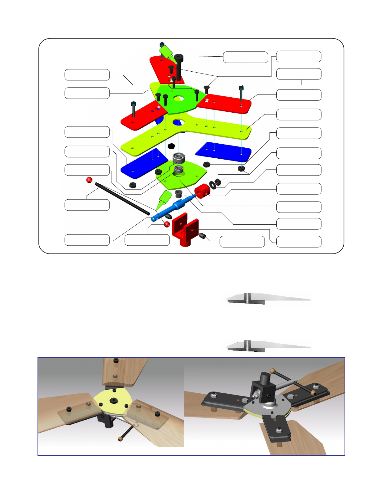
1) Slide the plastic tubes (E, F) onto the vee-shaped steel landing gear wires (D). Insert the assemblies into each side of the
body. Looking from the front, make sure the wires are horizontal. Glue the front wires to the body.
2) Screw the plastic axle fittings (I) to the bottom of the main landing gear legs (J) with screws (L). Do not tighten fully yet.
3) Slide the upper struts (A) into the plastic fittings (K) and insert into the body. Do not glue yet. Insert the middle of the landing
gear wire assembly (D,E,F) between the plastic fitting (K) and the landing gear leg (J) and screw together with screw (L).
4) Slide the steel wire axles (G) into the lower plastic fittings (H) and insert the spruce struts (B, C). The axle wire should allow the
struts to fit into the socket. Do not glue yet..
5) Insert the steel wire axles (G) into the landing gear leg fittings (I). Then slip the lower struts (B, C) into the bottom slots on the
body and tighten the screws.
6) Check and adjust the landing gear looking from the front, top and both sides. Glue all spruce-to-plastic joints with
cyanoacrylate (CA).
7) Glue each of the other joints while checking alignment.
8) Paint the landing gear.
9) Slip the main wheels (M) onto the axles, and secure with safety lock (N).
10) Glue together the halves of the tail wheel (Q), slide onto tail wheel wire and glue the tail gear assembly to the body
For gluing polystyrene parts, as well as spruce, plywood, and plastic, use EPOXY.
CAUTION Cyanoacrylate (CA) glue will melt the polystyrene body.
G 0408
G 0417
G O310
G 0407
G 0422
G 0306
G 0327
G 0303
G 0411
G 0414
GL 004
GL 001
G 0309
G 0307
G0302
G 0304
G 0305 G 0410 G 0301
CA
L
G 0423
Sestavení rotorové hlavy / Rotor head assembly
Sestavení
1) Šroub G0423 zajištìn LOCTICE.
2) Rotorové listy vybrousíme jemným brusným papírem do hladka, povrchovou úpravu provedeme buï
lakováním, potahem samolepící páskou nebo zasmrštìním listù do tenké smršovací folie.
Listy v pøípadì potøeby dovyváíme.
3) Na takto pøipravené listy nalepíme plastové podloky dle obr.
(zkompletované listy zatím na rotorovou hlavu nemontujeme)
Assembly
1) Screw G0423 should be fixed with Loctite
2) Sandpaper with fine sandpaper to achieve a smooth surface. The finish can be either lacquer, thin
adhesive tape, or heat-shrink plastic film. Blades should be balanced if necessary.
3) Finalize blades by gluing plastic pads as shown in the picture.
(Finalize blades on rotor head no assemble yet)
G 5308
Kompletace / Assembly
1) Sestavenou rotorovou hlavu nasadíme do trubky na trupu, zalepíme (dbáme pøitom na souosost s trupem) a doplníme
o táhla od serv
2) Nainstalujeme elektromotor, regulátor a pøijímaè
!!POZOR!! Je nutné dodret rozmístìní elektroniky vèetnì doporuèené hmotnosti jednotlivých komponent,
v pøípadì zmìny proveïte dováení.
3) Na trup upevníme maketu motoru a doplníme o výfuk, na elektromotor namontujeme vrtuli.
4) Na model nalepíme pøiloené obtisky
5) Namontujeme vyváené rotorové listy a provedeme základní seøízení a naprogramování vysílaèe
1) Assembled rotor head put to the rotor mast on body and glue (see at the same time on alignment with body) and complete
about rod from servos
2) Install electric motor, regulator and receiver
ATTENTION! You must keep recommended component placing including component weight. In case of differences
you must carefully balance the model.
3) On body fix mock-up engine and complete about exhaust, on electric motor mount propeller.
4) On model stick enclosed decals
5) Assembled balanced rotor blades and make basic setting and programmed transmitters
2 x servo HS 55 Y9055
(2x10 g)
Regulátor 8A G 9001
(10 g)
Controller 8A.G 9001
Vrtule APC 7x4 G0451
+ unašeè G 0450
(5,5 + 5 g)
Propeller APC 7x4 G0451
+ prop.support G 0450
Motor G 9002
(30 g)
RX REX 4 G 9001
(10g)
Baterie 11,1V
Battery 11,1V
(130-150 g)
E L E K T R O N I K A / E L E C T R O N I C
Létání
1) Zkontrolujeme všechny funkce øízení a základní nastavení.
2) První lety provádíme nejlépe za mírného protivìtru na dostateènì velké otevøené ploše bez pøekáek.
3) Model vdy startujeme proti i mírnému vìtru.
4) Rukou provedeme pøedtoèení rotoru doleva. (pomùe úplné pøitaení rotoru smìrem dozadu a pøidání
plynu)
5) Pøidáme cca 50-75% plynu
6) Nìkolika rychlými kroky roztoèíme rotor na poadované otáèky (poznáme to podle toho, e rotor táhne
model nahoru), poté jej podrovnáme a vypustíme stejnì, jako model letadla.
7) Provedeme dotrimování pøípadnì upravíme výchylky dle poadavkù.
8) Pøistání provádíme se zapnutým motorem aby byla zaruèena dopøedná rychlost a zásadnì proti vìtru.
Flight
1) Check all functions and basic setup before every flight
2) First flight should be performed at free space without barrier, mild wind to face is welcome
3) Model MUST take off ahead to wind
4) Spin-up the rotor with free hand. (You can tilt rotor full back and apply mild throttle to help spinning up)
5) Set 50-75% throttle
6) Make few steps forward (short slow run) to make rotor lifting the model and free it as it is standard
slowflyer plane
7) Trim the leveled flight
8) Landing must be done with mild throttle to avoid stopping the model, allways towards wind.
Základní seøízení
1) Páky serv v neutrálu do pravého úhlu
2) Ve vysílaèi nastavit delta mix.
3) Základní záklon je 6°, pøíènì 0°.
4) Výchylky hlavy 8°na všechny strany, pokud to umoòuje rádio, výškovku na potlaèeno (dopøedu) omezit
na 6°.
5) !!POZOR!! Je nutné dodret rozmístìní elektroniky vèetnì doporuèené hmotnosti jednotlivých
komponent, v pøípadì zmìny proveïte dováení.
Basic setup
1) Servo levers should be perpendicular at neutral signal.
2) Use „delta wing“ mixer at the radio.
3) Basic tilt is 6 deg to back, 0 deg to side.
4) Basic servo travel is till 8 deg tilt (The forward tilt can be reduced for 6 deg, if radio has limitation for this
movement).
5) ATTENTION! You must keep recommended component placing including component weight. In
case of differences you must carefully balance the model.

Other LA-Heli Toy manuals

LA-Heli Sniper II User manual

LA-Heli

LA-Heli Sniper II User manual

LA-Heli Ricco User manual

LA-Heli

LA-Heli Ricco User manual

LA-Heli maxir 2008 User manual

LA-Heli

LA-Heli maxir 2008 User manual

LA-Heli Sniper II User manual

LA-Heli

LA-Heli Sniper II User manual

Popular Toy manuals by other brands

Schweizer 300CB Rotorcraft Flight Manual Supplement

Schweizer

Schweizer 300CB Rotorcraft Flight Manual Supplement

Hanayama CAST PUZZLE Key to Enigma manual

Hanayama

Hanayama CAST PUZZLE Key to Enigma manual

Hobbico FlyZone Sky Scream Assembly manual

Hobbico

Hobbico FlyZone Sky Scream Assembly manual

LEXIBOOK JCPAD100SPi2 instruction manual

LEXIBOOK

LEXIBOOK JCPAD100SPi2 instruction manual

Faller BEETHOVENSTRASSE manual

Faller

Faller BEETHOVENSTRASSE manual

Blade Glimpse BLH2200 user manual

Blade

Blade Glimpse BLH2200 user manual

LEGO 70336 manual

LEGO

LEGO 70336 manual

LEGO 60041 instructions

LEGO

LEGO 60041 instructions

LEGO 21307 Assembly instruction

LEGO

LEGO 21307 Assembly instruction

Trainers Warehouse Me First Personal Answer Domes instructions

Trainers Warehouse

Trainers Warehouse Me First Personal Answer Domes instructions

REVELL KIT 5715 Assembly manual

REVELL

REVELL KIT 5715 Assembly manual

Click 3D Install manual

Click

Click 3D Install manual

Ripmax Acro Wot mk2 instruction manual

Ripmax

Ripmax Acro Wot mk2 instruction manual

Fit N'Fun 9300M Hickory Hills Owner's manual and assembly instructions

Fit N'Fun

Fit N'Fun 9300M Hickory Hills Owner's manual and assembly instructions

Fisher-Price Pixter color CREATIVE GENIUS C1450 owner's manual

Fisher-Price

Fisher-Price Pixter color CREATIVE GENIUS C1450 owner's manual

arf MX2 50CC V2 instruction manual

arf

arf MX2 50CC V2 instruction manual

LEGO 8109 TECHNIC Assembly guide

LEGO

LEGO 8109 TECHNIC Assembly guide

Mega Construx POKEMON WONDER BUILDERS CFV87 manual

Mega Construx

Mega Construx POKEMON WONDER BUILDERS CFV87 manual

manuals.online logo
manuals.online logoBrands
  • About & Mission
  • Contact us
  • Privacy Policy
  • Terms and Conditions

Copyright 2025 Manuals.Online. All Rights Reserved.