Laars SC6 User manual

Laars Sequencing Controls
Document 4200
LINE
NEUT
OUTPUT 8
OUTPUT 9
OUTPUT 7
OUTPUT 10
OUTPUT 11
OUTPUT 12
INCREMENT
AUTO
OFF
LEAD STAGE
ROTATION
SELECT
SETTING
UP
DOWN
INPUTS
1 2 3 45 6 7 8910
SAFETY
GROUND
MUST BE
CONNECTED
11 12
Sensor Com Shield + Sensor Com Dry Contact
Only
Dry Contact
Only
TEMP SHUTDOWN
/SETBACK
PROVE
/DHW
SYSTEM
Output 7
OFF
AUTO
ON
Output 8
OFF
AUTO
ON
Output 9
OFF
AUTO
ON
Output 10
OFF
AUTO
ON
Output 11
OFF
AUTO
ON
Output 12
OFF
AUTO
ON
OFF
AUTO
ON
OUTPUT 1
OUTPUT 2
OUTPUT 3
OUTPUT 4
OUTPUT 5
OUTPUT 6
Output 1
OFF
AUTO
ON
Output 2
OFF
AUTO
ON
Output 3
OFF
AUTO
ON
Output 4
OFF
AUTO
ON
Output 5
OFF
AUTO
ON
Output 6
OFF
AUTO
ON
System
LEAD
OUTPUT ON
4-20 ma OUTDOOR
SC
Non-Modulating
Model SC6, SC6P
and SC 12
Output panel to Sequence
up to 12 individual
stages with lead-lag and
manual override capabilities
Installation and Operation Instructions
FOR YOUR SAFETY:
This product must be installed and serviced by a
professional service technician, qualifi ed in hot water heater/boiler controls
installation and maintenance. This manual is intended for anyone who will
install, operate or maintain the control system. Before you begin installation
and operation of this control, it is important that you thoroughly review this
manual. Improper installation and operation could result in damage to
equipment and possibly even personal injury. Laars Sequencing Controls are
not intended for use as operation safety limit controls. Another control, which
is intended and certifi ed as a high limit control, must be in the boiler/heater
control circuit.

Page 2
LAARS Heating Systems
Contents
SC FUNCTION CHART . . . . . . . . . . . . . . . . . . . . . . . . . . . . . . . . . . . . . . . . . . . . . . . . . . . . . . . . . . 3
DIP SWITCH CHART . . . . . . . . . . . . . . . . . . . . . . . . . . . . . . . . . . . . . . . . . . . . . . . . . . . . . . . . . . . . 4
INSTALLATION . 5
MOUNTING THE SC . . . . . . . . . . . . . . . . . . . . . . . . . . . . . . . . . . . . . . . . . . . . . . . . . . . . . . . . . . . . . 5
SET THE DIP SWITCHES . . . . . . . . . . . . . . . . . . . . . . . . . . . . . . . . . . . . . . . . . . . . . . . . . . . . . . . . . . 5
WIRING THE POWER INPUTS . . . . . . . . . . . . . . . . . . . . . . . . . . . . . . . . . . . . . . . . . . . . . . . . . . . . . . . . 5
WIRING THE INPUT TERMINALS . . . . . . . . . . . . . . . . . . . . . . . . . . . . . . . . . . . . . . . . . . . . . . . . . . . . . . 5
WIRING THE STAGE OUTPUTS . . . . . . . . . . . . . . . . . . . . . . . . . . . . . . . . . . . . . . . . . . . . . . . . . . . . . . . 7
WIRING THE SYSTEM OUTPUT . . . . . . . . . . . . . . . . . . . . . . . . . . . . . . . . . . . . . . . . . . . . . . . . . . . . . . 7
BEFORE POWER UP . . . . . . . . . . . . . . . . . . . . . . . . . . . . . . . . . . . . . . . . . . . . . . . . . . . . . . . . . . . . . 7
POWER UP SEQUENCES . . . . . . . . . . . . . . . . . . . . . . . . . . . . . . . . . . . . . . . . . . . . . . . . . . . . . . . . . . 8
ADJUSTING THE CONTROL SETTING . . . . . . . . . . . . . . . . . . . . . . . . . . . . . . . . . . . . . . . . . . . . 10
SET POINT CONTROL WITH NORMAL SEQUENCING . . . . . . . . . . . . . . . . . . . . . . . . . . . . . . . . . . . . . . . . 10
DIP SWITCH 8 - OFF . . . . . . . . . . . . . . . . . . . . . . . . . . . . . . . . . . . . . . . . . . . . . . . . . . . . . . . . . . . 10
SET POINT CONTROL WITH OSS SEQUENCING . . . . . . . . . . . . . . . . . . . . . . . . . . . . . . . . . . . . . . . . . . 11
OUTDOOR RESET WITH NORMAL SEQUENCING . . . . . . . . . . . . . . . . . . . . . . . . . . . . . . . . . . . . . . . . . . . 12
OUTDOOR RESET WITH OSS SEQUENCING . . . . . . . . . . . . . . . . . . . . . . . . . . . . . . . . . . . . . . . . . . . . . 13
SC-6 AND SC-12 OUTPUT WIRING . . . . . . . . . . . . . . . . . . . . . . . . . . . . . . . . . . . . . . . . . . . . . . . 14
WIRING THE STAGE OUTPUTS . . . . . . . . . . . . . . . . . . . . . . . . . . . . . . . . . . . . . . . . . . . . . . . . . . . . . . 14
SC-6P OUTPUT WIRING . . . . . . . . . . . . . . . . . . . . . . . . . . . . . . . . . . . . . . . . . . . . . . . . . . . . . . . . 15
WIRING THE STAGE OUTPUTS . . . . . . . . . . . . . . . . . . . . . . . . . . . . . . . . . . . . . . . . . . . . . . . . . . . . . . 15
SAMPLE WIRING AND PLUMBING DIAGRAMS . . . . . . . . . . . . . . . . . . . . . . . . . . . . . . . . . . . . . 16
OUTPUT RELAY CHARTS . . . . . . . . . . . . . . . . . . . . . . . . . . . . . . . . . . . . . . . . . . . . . . . . . . . . . . . 17
OPERATION . . 18
SET POINT CONTROL SETTINGS . . . . . . . . . . . . . . . . . . . . . . . . . . . . . . . . . . . . . . . . . . . . . . . . . . . . 18
OUTDOOR RESET SETTINGS . . . . . . . . . . . . . . . . . . . . . . . . . . . . . . . . . . . . . . . . . . . . . . . . . . . . . . . 19
NORMAL SEQUENCING SETTINGS . . . . . . . . . . . . . . . . . . . . . . . . . . . . . . . . . . . . . . . . . . . . . . . . . . . . 20
OVERSIZE SYSTEM SEQUENCING SETTINGS . . . . . . . . . . . . . . . . . . . . . . . . . . . . . . . . . . . . . . . . . . . . 21
SYSTEM OUTPUT SETTINGS . . . . . . . . . . . . . . . . . . . . . . . . . . . . . . . . . . . . . . . . . . . . . . . . . . . . . . . 22
LEAD STAGE . . . . . . . . . . . . . . . . . . . . . . . . . . . . . . . . . . . . . . . . . . . . . . . . . . . . . . . . . . . . . . . . . 22
OUTPUT CONTROLS . . . . . . . . . . . . . . . . . . . . . . . . . . . . . . . . . . . . . . . . . . . . . . . . . . . . . . . . . . . . 23
EXTERNAL SET POINT . . . . . . . . . . . . . . . . . . . . . . . . . . . . . . . . . . . . . . . . . . . . . . . . . . . . . . . . . . . 23
TROUBLESHOOTING . . . . . . . . . . . . . . . . . . . . . . . . . . . . . . . . . . . . . . . . . . . . . . . . . . . . . . . . . . 26
LIMITED WARRANTY . . . . . . . . . . . . . . . . . . . . . . . . . . . . . . . . . . . . . . . . . . . . . . . . . . . . . . . . . . 28

Page 3
Laars Sequencing Controls
SC FUNCTION CHART
LINE
NEUT
OUTPUT 8
OUTPUT 9
OUTPUT 7
OUTPUT 10
OUTPUT 11
OUTPUT 12
INCREMENT
AUTO
OFF
LEAD STAGE
ROTATION
SELECT
SETTING
UP
DOWN
INPUTS
1 2 3 45 6 7 8910
SAFETY
GROUND
MUST BE
CONNECTED
11 12
Sensor Com Shield + Sensor Com Dry Contact
Only
Dry Contact
Only
TEMP SHUTDOWN
/SETBACK
PROVE
/DHW
SYSTEM
Output 7
OFF
AUTO
ON
Output 8
OFF
AUTO
ON
Output 9
OFF
AUTO
ON
Output 10
OFF
AUTO
ON
Output 11
OFF
AUTO
ON
Output 12
OFF
AUTO
ON
OFF
AUTO
ON
OUTPUT 1
OUTPUT 2
OUTPUT 3
OUTPUT 4
OUTPUT 5
OUTPUT 6
Output 1
OFF
AUTO
ON
Output 2
OFF
AUTO
ON
Output 3
OFF
AUTO
ON
Output 4
OFF
AUTO
ON
Output 5
OFF
AUTO
ON
Output 6
OFF
AUTO
ON
System
LEAD
OUTPUT ON
4-20 ma OUTDOOR
SC
Digital display reads
sensor value constantly
Install a relay for
each output stage
which will be active
Use these three buttons
to adjust the settings
In AUTO, the lead stage will automatically
rotate among the active outputs. Press to
INCREMENT for manual rotation.
Each Stage
Output has
one set of
N.O. contacts
The green LEAD stage
light indicates which
stage will be activated
first on a system call
The red OUTPUT lights
indicate when the relays
are energized and the
N.O. contacts are
continuous.
The System
Output is
SPDT
Each output can be switched
ON, AUTO, or OFF. In AUTO,
the output will be controlled
based on system requirements.
120 VAC Power Input
GND must be connected
Sensor, Shutdown/Setback,
Prove/DHW, and Outdoor
input terminals

Page 4
LAARS Heating Systems
DIP SWITCH CHART
1 2 3 4 5 6 7 8
ON
Switch 1
System Output
Switch 5
Rotation
Switches 6 and 7
Input Type
5
First On/Last Off
Lead stage rotates
every 24 hours
5
First On/First Off
First stage on is
the first stage
turned off
Temperature
6 7
External Set Point
Available for temperature
systems only, 4-20mA
signal changes Set Point
6 7
ON
ON
ON
ON
Switch 8
Set Point or Reset
8
Set Point
Set Point control
for temperature
8
Outdoor Reset
Hydronic heating
control with
outdoor reset
ON
ON
1
System Pump
SYSTEM relay is on
based on outside
temp, Shutdown,
and DHW priority
1
Combustion Air
Damper/Prove
SYSTEM relay is
on when any
OUTPUT is on
ON
ON
Switches 2, 3, and 4
Stage Type
2Stage Lo/Lo/Hi/Hi
On load increase
sequence on Lo
stages first, then Hi
stages
2
On/Off Stages
Each stage is
either on or off
2 Stage Lo/Hi
On load increase
sequence Lo to Hi
then next Lo to Hi
3 4
2 3 4
2
3 Stages
On load increase
sequence Lo, Mid,
Hi
3 4
234
4 Stages
On load increase
sequence Lo,
LoMid, HiMid, Hi
234
ON
ON
ON
ON
ON
ON

Page 5
Laars Sequencing Controls
INSTALLATION
MOUNTING THE SC
• Select a location near the equipment to be controlled.
• The surface should be fl at, and be suffi ciently wide and strong to hold the SC.
• Keep the control away from extreme heat or cold. Ambient operating
temperature is from 20 to 120°F.
• Remove the panel from the metal enclosure by removing the top center screw
and loosening the two screws at the bottom of the panel. Lift the panel out.
• Screw the enclosure to the surface through the mounting holes in the back of
the enclosure.
• Be sure to set the dip switches before returning the panel to the enclosure.
SET THE DIP SWITCHES
• The dip switch chart is shown on page 4.
• The dip switch is located on the back on the SC board (the side of the board without
the metal front panel).
• The dip switch sets all of the following:
- System relay output type - Combustion Air Damper, or System Pump operation
- Stage type - On/Off, Lo/Hi, 3 Stage or 4 Stage
- Rotation Sequence - First On/Last Off or First On/First Off
- Input type - Temperature or External Set Point
- Operation - Set Point or Outdoor Reset
IMPORTANT
The dip switches must be set correctly. Carefully, check the details of the installation and
determine the appropriate dip switch settings before continuing on to the next steps.
WIRING THE POWER INPUTS
• Bring the 120VAC 60Hz power wires through a bottom knock out of the enclosure.
Class 1 voltages must enter the enclosure through a different opening from any Class 2
voltage wiring.
• Connect the hot line to terminal marked
LINE.
• Connect the neutral line to the terminal marked
NEUT.
• The green ground screw must be connected to earth ground.
• Wiring a surge suppressor is recommended before wiring to the SC Control.
WIRING THE INPUT TERMINALS
System Temperature Sensor - Terminals
1, 2,
and
3
• The System Temperature Sensor must be installed for the control to operate correctly.
• The SC is designed to be connected to standard brass tube sensor (Laars Part # CA002400).
Contact the factory for additional temperature sensor options.
• Sensor must inserted in a 3/8” well (Laars Part # CA002500).
• Locate the sensor where it will register the water temperature output of all the stages. Sensor
should
NOT
be installed in between boiler connections to header. If the sensor does not
register the output of all the stages, it will not be able to Sequence properly.
• Temperature sensor wires can be extended up to 500’ by splicing with 18 gauge shielded wire.
• Do not run wire in conduit with line voltage.
• Temperature sensors have no polarity. Connect either wire from the sensor to terminal
1 SENSOR
.
• Connect the other sensor wire to terminal
2 COM
.
2 COM.2 COM
• Connect the shield to terminal
3 SHIELD
.
NOTICE
If the dip switch is changed
during operation, the SC will be
completely reset. Wait until the
SC restarts and then reprogram
all settings.
Mounting Holes
LINE
NEUT
Surge
Suppressor
Power Switch
Ground
Line
Neut
INPUTS
1 2 3 45 6
Sensor Com Shield + Sensor Com
TEMP PRES 4-20 ma
Shield
To Temperature Sensor
in Common Header

Page 6
LAARS Heating Systems
External Set Point - Terminals
4, 5,
and
6
• The SC can accept a 4-20mA signal from an Energy Management System (EMS) or other signal
source to change the Set Point remotely (see pg. 23).
• Dip switch 6 and 8 must be
OFF
and dip switch 7 must be
OFF and dip switch 7 must be OFF
ON
. These settings will allow the
ON. These settings will allow the ON
SC to read and monitor the system water temperature using the System temperature sensor and
monitor the 4-20mA input to change the set point. (See wiring sensor on pg. 3) Also, see pg. 23 for
EMS programming parameters.
Shutdown or Setback - Terminals
7
and
7 and 7
8
• When adjusting control
SETBACK
Stb
setting to 0 the
SHUTDOWN
feature is enabled by
SHUTDOWN feature is enabled by SHUTDOWN
closing a dry contact and all active stages are turned off. Any pumps controlled by the SC that
were on will remain on until the System Delay is over, then they will also turn off.
• The
SHUTDOWN
feature can be used whenever it is desirable to turn off the SC from a remote
SHUTDOWN feature can be used whenever it is desirable to turn off the SC from a remote SHUTDOWN
location or another controller (for more details see pg. 24).
• When
SETBACK
Stb
is enabled by adjusting control
SETBACK
Stb
setting to a value higher
than 0 and closing a dry contact wired to terminals 7 and 8, the SC will immediately reduce the
temperature of the circulating hot water by the
SETBACK
Stb
setting amount (see pg. 20 to
adjust the amount of
SETBACK)
. All pumps controlled by the SC that were on will remain on until the
System Delay is over, then they will turn off.
• The
SHUTDOWN/SETBACK
signal must be a dry contact only to terminals 7 and 8. No voltage can be
SHUTDOWN/SETBACK signal must be a dry contact only to terminals 7 and 8. No voltage can be SHUTDOWN/SETBACK
placed across the
SHUTDOWN/SETBACK
terminals.
SHUTDOWN/SETBACK terminals.SHUTDOWN/SETBACK
Prove or Domestic Hot Water (DHW) Input - Terminals
9
and
9 and 9
10
• The Prove or Domestic Hot Water features are set by the External Input Mode in the Power Up
Sequence. It can be switched between Prove (
Pr
) and Domestic Hot Water (
dh
).
• The
PROVE
feature is used to check system components’ operation before activating any stages. See
PROVE feature is used to check system components’ operation before activating any stages. See PROVE
pg. 24 for typical applications.
• If the
PROVE
input terminals are open, the SC will enable only the System Output relay. All Stage
PROVE input terminals are open, the SC will enable only the System Output relay. All Stage PROVE
Outputs will be off when the
PROVE
input is open.
PROVE input is open.PROVE
• When the Domestic Hot Water (
DHW
• When the Domestic Hot Water (DHW• When the Domestic Hot Water (
) input is enabled by closing a dry contact, the Calculated water
DHW) input is enabled by closing a dry contact, the Calculated water DHW
temperature or the Set Point will change to 200°F and the decimal point on the left-most digit on the
display will fl ash.
• The
DHW
input will take priority over the outdoor reset function or the Outdoor Cutoff temperature.
DHW input will take priority over the outdoor reset function or the Outdoor Cutoff temperature. DHW
Regardless of outdoor temperature, when the
DHW
input is closed, the SC will Sequence stages to
DHW input is closed, the SC will Sequence stages to DHW
hold 200°F.
• If
NO
external conditions must be met before Stage Output is activated and terminals
9
and
10
are not used for Domestic Hot
Water (see pg. 25),
DO NOT
remove the factory installed jumper across the
PROVE/DHW
terminals.
PROVE/DHW terminals.PROVE/DHW
• The
PROVE/DHW
signal must be a dry contact only to terminals 9 and 10. No voltage can be placed across the
PROVE/DHW signal must be a dry contact only to terminals 9 and 10. No voltage can be placed across the PROVE/DHW
PROVE/DHW
terminals.
IMPORTANT
FACTORY INSTALLED PROVE JUMPER: The
PROVE
input terminals must be
PROVE input terminals must be PROVE
shorted for Stage Outputs to be activated. DO NOT remove the factory installed
PROVE jumper unless replacing it with a Prove or Domestic Hot Water signal.
Outdoor Sensor- Terminals
11
and
12
• The Outdoor Sensor must be installed if the Outdoor Reset operational mode is required (dip switch 8
ON
).
ON).ON
• Installing the Outdoor Sensor is optional in the Set Point mode (dip switch 8
OFF
). If it is installed, it will act as an Outdoor
OFF). If it is installed, it will act as an Outdoor OFF
Cutoff (see pg. 18). No stages will be activated when the outdoor temperature is above the Outdoor Cutoff.
• Locate the Outdoor sensor in the shade on the north side of the building away from doors,
windows, exhaust fans, vents, or other possible heat sources.
• The sensor should be mounted at least 4 inches away from the building wall and
approximately 10 feet above ground level.
• Sensor wires can be extended up to 500’ by splicing with 18 gauge shielded wire.
• Do not run sensor wire in conduit with line voltage.
• Temperature sensors have no polarity. Connect either wire to terminal
11
and 12.
• Connect the shield to terminal
3 SHIELD.
Note that both sensor shields will be connected
to terminal 3.
Dry Contact
Prove or Domestic
Hot Water Signal
INPUTS
5 6 7 8910 11
Sensor Com Dry Contact
Only
Dry Contact
Only
SHUTDOWN
/SETBACK
PROVE
/DHW
OUTD
4-20 ma
INPUTS
5678910 11 12
Sensor Com Dry Contact
Only
Dry Contact
Only
SHUTDOWN
/SETBACK
PROVE
/DHW
4-20 ma OUTDOOR
To Outdoor Sensor
In Shade
Shield
2 3 4
Com Shield +
TEMP
45 6
+ Sensor Com
4-20 ma
SC Source Current
24VDC Excitation Voltage
(-) Input
(+) Signal
INPUTS
5 6 7 89
Sensor Com Dry Contact
Only
Dry Contact
SHUTDOWN
/SETBACK
PROVE
4
+
4-20 ma
Dry Contact
Shutdown and
Setback Signal
45 6
+ Sensor Com
4-20 ma
EMS Sourcing Current
(-) Input
(+) Signal

Page 7
Laars Sequencing Controls
WIRING THE STAGE OUTPUTS
• For SC-6 and SC-12 see pg. 14.
• For SC-6P see pg. 15.
WIRING THE SYSTEM OUTPUT
Combustion Air Damper
• To select the Combustion Air Damper mode of operation, Dip Switch 1 must be
OFF
.
• Wire the Air Damper to System relay terminals marked C and N.O.
• The Combustion Air Damper option causes the System relay to act as follows:
- If there is no call for stage output, the System relay is off
- On a call for stage output, the System relay is energized
- When the
PROVE
input is made, the lead stage is energized
PROVE input is made, the lead stage is energizedPROVE
- The System relay remains energized as long as any stage is active
- When the last stage turns off, the System relay remains energized for the period of
time set by the System Delay (see pg. 22)
- Then the System relay is turned off.
• To give the damper time to open, wire the damper motor end switch into the
PROVE
inputs. The
PROVE inputs. The PROVE
PROVE
input can be used in a
PROVE input can be used in a PROVE
similar fashion to provide a delay for any equipment being energized by the System relay.
• The Combustion Air Damper operation can also be used to activate any piece of equipment that should be on whenever any stage
is active or can provide a signal to other equipment that one or more stages of the SC has been activated.
• The System Relay is a SPDT output capable of switching 6A resistive.
• Check the wiring information provided by the damper motor or other equipment manufacturer for the appropriate method to
activate the equipment with a SPDT output.
System Pump
• To select the System Pump mode of operation, Dip Switch 1 must be
ON
.
ON.ON
• Wire the System Pump to System relay terminals marked C and N.O.
• When there is no call for DHW, the System relay will be energized whenever the
Outdoor temperature is below the Outdoor Cutoff
COF
and the Shutdown is not
active. The System relay will remain energized even if all Output Stages are off.
• If an outdoor sensor is not connected or registers a fault condition:
- The System relay will be energized when any stage is active
- After the last stage is turned off, the System relay will remain energized for the period of time set by the System Delay (see pg.
22) and then turn off.
• When the control is set for “no DHW priority” (see pgs. 8 and 9) and there is a call for DHW:
- When the outdoor temperature below the Outdoor Cutoff + 2°F (
COF
+ 2°F), the
System relay output will be active.
- Otherwise, the System relay will be off above
COF
+ 2°F (after the System Delay
Sd
has expired).• When the control is set
for “DHW priority” (see pgs. 8 and 9):
• When the control is set for “DHW priority” (see pgs. 8 and 9):
- The System relay will be off for an adjustable period of time set by the DHW Priority Time
dhP
.
- After the Priority Time has elapsed, when the outdoor temperature is below the Outdoor Cutoff + 2°F (
COF
+ 2°F) setting, the
System relay will be energized.
- When the outdoor temperature is 2°F above the Outdoor Cutoff (
COF
+
2°F), the System relay will be off at all times.
• The system output is capable of switching 6A resistive.
BEFORE POWER UP
• The dip switches must be set correctly for the application. Check the dip
switch chart on pg. 4 to make sure the SC is set properly before power up.
• Each Stage Output which is to be active (and has a relay installed) should have its
OFF/AUTO/ON
switch in the
OFF/AUTO/ON switch in the OFF/AUTO/ON
AUTO
position.
• Any Stage Output which is not to be active (or any output without a relay) should have its
OFF/AUTO/ON
switch in the
OFF/AUTO/ON switch in the OFF/AUTO/ON
OFF
position.
• Set the
LEAD STAGE
switch in the
LEAD STAGE switch in the LEAD STAGE
AUTO
position for automatic rotation.
SYSTEM
C.
N.C.
N.O.
Combustion
Air Damper
Line
Neut
SYSTEM
C.
N.C.
N.O.
System Pump
Line
Neut
WARNING
WARNING
The SC is NOT a safety
control. Make sure damper
is wired back into boiler for
safety.
NOTICE
The SC DOES NOT source
power. A separate power
source must be supplied for
equipment being controlled.

Page 8
LAARS Heating Systems
POWER UP SEQUENCES
• Whenever the SC is powered up, it displays the software version number and then the
operating parameters. Each display will remain on the screen approximately 5 seconds. If
the parameters are correct, there is no need to make any adjustments.
• Once the parameters have been set for a particular application, they will be retained in memory and will not need to be reset.
• Note that if you do change any parameter, or make any changes to the dip switch positions, all
settings will revert to their default values and must be reset.
• A parameter can only be changed in the start-up Sequence. To restart, it is necessary to remove and
reapply power.
• Set the parameters to fi nd the appropriate Sequence for your application, Set Point Control -
Temperature and External Set Point (pgs. 10 and 11) or Outdoor Reset (pgs. 12 and 13)
Set Point Control - Temperature and External Set Point
Temperature Display Mode
Default: Fahrenheit
• The SC can be fi eld adjusted to read temperature sensors and display the Set Point either in °F or °C.
• The sensor input range is from -35 to 250°F or from -30° to 120°C.
• If the display shows
°F
the SC will operate in Fahrenheit. If the display shows
°F the SC will operate in Fahrenheit. If the display shows °F
°C
then the SC will operate in Celsius.
°C then the SC will operate in Celsius.°C
• To change the temperature display mode, hold down the center button while pushing either the
UP
button to increase the value,
UP button to increase the value, UP
or the
DOWN
button to decrease the value.
DOWN button to decrease the value.DOWN
• When the correct display mode is shown, release the button and wait approximately 5 seconds. If any changes were made, the
display will fl ash.
Set Input Terminals 9 and 10 to PROVE or DHW
Default: Prove
Pr
• If the system is designed to provide heat and DHW, the SC can be programmed to hold a 200°F Setpoint when a call for DHW is
connected to Input terminals
9
and
10
(see pg. 25).
• All other applications should use the default Prove setting (see pg. 24).
• If the display shows
Pr
the Input terminals
9
and
10
will function in the Prove mode. If the display shows
dh
then the same
terminals will function in the DHW mode.
• To change the Input terminal functions, hold down the center button while pushing either the
UP
button to increase the value, or
UP button to increase the value, or UP
the
DOWN
button to decrease the value.
DOWN button to decrease the value.DOWN
• When the correct value is shown, release the button and wait approximately 5 seconds. If any changes were made, the display
will fl ash.
Set the Sequencing Mode
Default: Normal
• For most applications, the
Normal
or PID type Sequencing mode provides the most stable operation. Stages are turned on or off
Normal or PID type Sequencing mode provides the most stable operation. Stages are turned on or off Normal
based on the rate of change of the system temperature and the impact a stage has on that rate.
• For applications where the stages are oversized for most load conditions, the SC has an Oversize System (
OSS
) Sequencing
mode that brings on stages proportionally, based on how high above or far below the Set Point the current system temperature is.
For more details, see pg. 21.
• If the display shows
nor
(Normal) then the SC will Sequence in the PID type mode. If the display shows
OSS
then SC will
Sequence stages based on a Throttling Range
thr
around the Set Point
SP
.
• To change the Sequence function, hold down the center button while pushing either the
UP
button to increase the value, or the
UP button to increase the value, or the UP
DOWN
button to decrease the value.
DOWN button to decrease the value.DOWN
• When the correct value is shown, release the button and wait approximately 5 seconds. If any changes were made, the display
will fl ash. This completes the startup Sequence and the SC will display the sensor temperature.
Outdoor Reset Control
Temperature Display Mode
Default: Fahrenheit
• The SC can be fi eld adjusted to read temperature sensors and display the Set Point either in °F or °C.
• The sensor input range is from -35 to 250°F or from -30 to 120°C.
• If the display shows
°F
the SC will operate in Fahrenheit. If the display shows
°F the SC will operate in Fahrenheit. If the display shows °F
°C
then the SC will operate in Celsius.
°C then the SC will operate in Celsius.°C
• To change the temperature display mode, hold down the center button while pushing either the
UP
button to increase the value,
UP button to increase the value, UP
or the
DOWN
button to decrease the value.
DOWN button to decrease the value.DOWN
• When the correct display mode is shown, release the button and wait approximately 5 seconds. If any changes were made, the
display will fl ash.
Minimum Water Temperature
Default: 140
°
F
• T
for the appropriate setting or call Laars for information.
INCREMENT
AUTO
OFF
LEAD STAGE
ROTATION
For Automatic Lead
Stage Rotation
Output
OFF
AUTO
ON
For Non-Active
Stages
For Stages Which are
to be Part of the
Automatic Sequence

Page 9
Laars Sequencing Controls
• The Minimum Water Temperature can be adjusted from 110°F to 180°F.
• To change the minimum water temperature, hold down the center button while pushing either the
UP
button to increase the
UP button to increase the UP
value, or the
DOWN
button to decrease the value.
DOWN button to decrease the value.DOWN
• When the correct value is shown, release the button and wait approximately 5 seconds. If any changes were made, the display
will fl ash.
Set Input Terminals 9 and 10 to PROVE or DHW
Default: Prove
Pr
• If the system is designed to provide heat and DHW, the SC can be programmed to hold a 200°F Setpoint when a call for DHW is
connected to Input Terminals
9
and
10
(see pg. 25).
• All other applications should use the default Prove setting (see pg. 24).
• If the display shows
Pr
the Input terminals
9
and
10
will function in the Prove mode. If the display shows
dh
then the same
terminals will function in the DHW mode.
• To change the Input terminal functions, hold down the center button while pushing either the
UP
button to increase the value, or
UP button to increase the value, or UP
the
DOWN
button to decrease the value.
DOWN button to decrease the value.DOWN
• When the correct value is shown, release the button and wait approximately 5 seconds. If any changes were made, the display
will fl ash.
Set the Sequencing Mode
Default: Normal
nor
• For most applications, the Normal or PID type Sequencing mode provides the most stable operation. Stages are brought on or off
based on the rate of change of the system temperature and the impact a stage has on that rate.
• For applications where the stages are oversized for most load conditions, the SC has a Oversize System
OSS
Sequencing mode
that brings on stages proportionally, based on how high above or far below the Set Point the current system temperature is. For
more details, (see pg. 21).
• If the display shows Normal
nor
then the SC will Sequence in the PID type mode. If the display shows
OSS
then SC will
Sequence stages based on a throttling range around the Set Point.
• To change the Sequence function, hold down the center button while pushing either the
UP
button to increase the value, or the
UP button to increase the value, or the UP
DOWN
button to decrease the value.
DOWN button to decrease the value.DOWN
• When the correct value is shown, release the button and wait approximately 5 seconds. If any changes were made, the display
will fl ash. This completes the startup Sequence and the SC will display the sensor temperature.

Page 10
LAARS Heating Systems
ADJUSTING THE CONTROL SETTING
• After the power up routine is complete, the display will show the system water temperature.
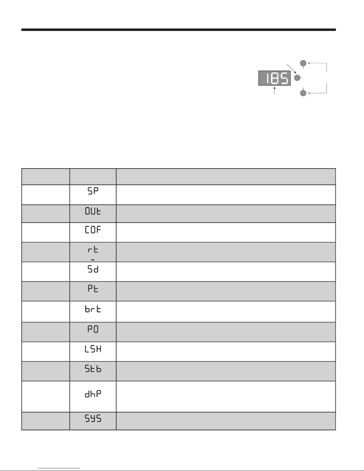
• To display the other control settings, repeatedly press the center
SELECT SETTING
button.
• A setting can only be adjusted when it is being displayed.
• Use the UP and DOWN buttons to adjust the setting.
• The display will always revert back to the actual system temperature after 30 seconds.
• Select the appropriate page from the list below for the available control settings for your
application:
Set Point Control with Normal Sequencing Temperature or External Set Point pg. 10
Set Point Control with Oversize System Sequencing Temperature or External Set Point pg. 11
Outdoor Reset Control with Normal Sequencing pg. 12
Outdoor Reset Control with Oversize System Sequencing pg. 13
SET POINT CONTROL WITH NORMAL SEQUENCING
Dip Switch 8 - OFF
Press SELECT
Button DISPLAY Press and hold either the UP or DOWN button to adjust
Once
Set Point
The Set Point is the temperature which the SC will sequence stages to hold. Note that if you are
using the External Set Point, you will not be able to change the Set Point unless you adjust the 4-
20mA input. The Set Point is adjustable between -30°F to 250°F. Default is 70°F.
Twice♦
Outdoor Temp
This is the outdoor sensor temperature value.
3 Times♦♦
Outdoor Cutoff
Available only when the outdoor sensor is installed. When the outdoor temperature falls below the
Outdoor Cutoff value, the SC will activate stages for heat. The Outdoor Cutoff can be set ON or OFF
and from 40 to 100°F. Default is 60°F.
3 or 4 Times
Reaction Time
The Reaction Time controls the minimum run time for a stage (1/2 the Reaction Time). Also, it con-
trols how long should a stage run before it activates/subtracts another stage. It is adjustable from half
a minute (0.5) to 8.0 minutes. Default is 2 minutes.
4 or 5 Times
System Delay
The System Delay controls how long the System relay will remain energized after the last Output has
been turned off or the outdoor temperature rises above the Starter. The System Delay is adjustable
from 0 to 30 minutes. Default is 0.
5 or 6 Times
Purge Time
The Purge Time should be set to the length of the unit’s purge cycle. The Purge Time will apply
when any ON/OFF unit is activated. On multiple stage units, the Purge Time will only apply to the Lo
stages. The Purge Time is adjustable from 0.0 to 10.0 minutes. Default is 0.
6 or 7 Times
Boiler runtime
This is the minimum amount of time any boiler will run after the Purge cycle has been completed. This
timer does not apply when only one stage is running, the Last Stage Hold LSH applies in that case.
The Boiler Runtime is adjustable between 0 to 60 minutes. Default is 0.
7 or 8 Times♦♦
Program Offset
The Programmed Offset fi ne tunes the External Set Point. With a known 4mA input, the offset can be
set to make the External Set Point 110°F. The Program Offset is adjustable between -10°F to +10°F.
Default is 0°F.
7 or more Times
Last Stage Hold
To prevent short cycling of the last stage in low load conditions, the system temperature can exceed
the Set Point by the amount selected by the Last Stage Hold before the last stage is turned off. The
Last Stage Hold is adjustable between 0°F to 20°F. Default is 10°F.
8 or more Times♦♦
Setback
The Setback adjusts the number of degrees the Set Point water temperature will be reduced when
Input terminals 7 and 8 are closed. If the Setback is set to 0, then the system will Shutdown on a
closure. The Setback is adjustable from 0°F to 40°F. Default is 0°F.
8 or more Times♦♦
DHW Priority Time
Only available when the System Output is set to System Pump (dip switch 1 is ON and dip switch 6 is
OFF ) This setting adjusts the amount of time the System relay output will remain off during a DHW
call. If the DHW call is not satisfi ed before the DHW priority time has elapsed, the System relay will
energize to provide heat. The DHW Priority is adjustable from 0 to 4 hours in half hour increments.
Default is 0.
8 or more Times♦
Default
The SC returns to the default display of system water temperature.
♦ Actual temperature values are not adjustable
♦♦ May not be available, depending on status of the outdoor sensor and dip switches.
SELECT
SETTING
UP
DOWN
Press and
Hold to
Adjust
Press to Scroll
Through Control
Settings
Control Settings
Display

Page 11
Laars Sequencing Controls
SET POINT CONTROL WITH OSS SEQUENCING
Dip Switch 8 - OFF
Press SELECT
Button DISPLAY Press and hold either the UP or DOWN button to adjust
Once
Set Point
The Set Point is the temperature which the SC will sequence stages to hold. Note that if you are
using the External Set Point, you will not be able to change the Set Point unless you adjust the 4-
20mA input. The Set Point is adjustable between -30°F to 250°F. Default is 70°F.
Twice♦
Outdoor Temp
This is the outdoor sensor temperature value.
3 Times♦♦
Outdoor Cutoff
Available only when the outdoor sensor is installed. When the outdoor temperature falls below the
Outdoor Cutoff value, the SC will activate stages for heat. The Outdoor Cutoff can be set ON or OFF
and from 40 to 100°F. Default is 60°F.
3 or 4 Time
System Delay
The System Delay controls how long the System relay will remain energized after the last Output has
been turned off or the outdoor temperature rises above the Starter. The System Delay is adjustable
from 0 to 30 minutes. Default is 0.
4 or 5 Times♦♦
Program Offset
The Programmed Offset fi ne tunes the Pressure input or the External Set Point. With a known 4mA
input, the offset can be set to make the External Set Point 110°F. The Program Offset is adjustable
between -10°F to +10°F. Default is 0°F.
4 or more Times
Throttling Range
The throttling range sets the number of degrees or psi above and below the Set Point where stages
will be turned on or off. The Throttle Range is adjustable from 1°F to 20°F. Default is 5°F. See page
24 for details.
5 or more Times♦♦
Setback
The Setback adjusts the number of degrees the Set Point water temperature will be reduced when
Input terminals 7 and 8 are closed. If the Setback is set to 0, then the system will Shutdown on a
closure. The Setback is adjustable from 0°F to 40°F. Default is 0°F.
5 or more Times♦♦
DHW Priority Time
Only available when the System Output is set to System Pump (dip switch 1 is ON and dip switch 6 is
OFF ) This setting adjusts the amount of time the System relay output will remain off during a DHW
call. If the DHW call is not satisfi ed before the DHW priority time has elapsed, the System relay will
energize to provide heat. The DHW Priority is adjustable from 0 to 4 hours in half hour increments.
Default is 0.
5 or more Times♦
Default
The SC returns to the default display of system water temperature.
♦ Actual temperature values are not adjustable
♦♦ May not be available, depending on status of the outdoor sensor and dip switches.

Page 12
LAARS Heating Systems
OUTDOOR RESET WITH NORMAL SEQUENCING
Dip Switch 6 and 7 - OFF and 8 - ON
Press SELECT
Button DISPLAY Press and hold either the UP or DOWN button to adjust
Once♦
Calculated
This is the water temperature the SC will stage outputs to hold. It is based on outdoor temperature,
Reset Ratio, and the Offset value. If OFF is shown, there is no call for heat. If PrF is shown, the SC
is waiting for a Prove signal before activating stages.
Twice♦
Outdoor Temp
This is the outdoor sensor temperature value.
3 Times
Outdoor Cutoff
When the outdoor temperature falls below the Outdoor Cutoff value, the SC will give heat. When the
outdoor temperature is above the Outdoor Cutoff, the Calculated value will be OFF and no stages will
be activated except on a DHW call. The Outdoor Cutoff can be set ON or OFF and from 40 to 100°F.
Default is 60°F.
4 Times
Reset Ratio
The Reset Ratio controls the amount of heat which enters the heating system based on the outdoor
temperature. A higher numbered Reset Ratio will result in a higher Calculated water temperature.
See the chart on pg. 19 for the reset curves. The Reset Ratio is adjustable from 1 to 12. Default is 7.
5 Times
Offset
The Offset moves the reset curves vertically up or down. For example, changing the offset from 0 to
-10 will decrease the water temperature 10°F regardless of outdoor temperature or the reset curve
selected. The Offset is adjustable from -40°F to 40°F. Default is 0°F.
6 Times
Reaction Time
The Reaction Time controls the minimum run time for a stage (1/2 the Reaction Time). Also, it con-
trols how long should a stage run before it activates/subtracts another stage. It is adjustable from half
a minute (0.5) to 8.0 minutes. Default is 2 minutes.
7 Times
System Delay
The System Delay controls how long the System relay will remain energized after the last Output has
been turned off or the outdoor temperature rises above the Starter. The System Delay is adjustable
from 0 to 30 minutes.
8 Times
Purge Time
The Purge Time should be set to the length of the unit’s purge cycle. The Purge Time will apply
when any ON/OFF unit is activated. On multiple stage units, the Purge Time will only apply to the Lo
stages. The Purge Time is adjustable from 0.0 to 10.0 minutes. Default is 0.
9 Times
Boiler runtime
This is the minimum amount of time any boiler will run after the Purge cycle has been completed. This
timer does not apply when only one stage is running, the Last Stage Hold LSH applies in that case.
The Boiler Runtime is adjustable between 0 to 60 minutes. Default is 0.
10 Times
Last Stage Hold
To prevent short cycling of the last stage in low load conditions, the system temperature can exceed
the Calculated water Temperature by the amount selected by the Last Stage Hold before the last
stage is turned off. The Last Stage Hold is adjustable between 0°F to 20°F. Default is 10°F.
11 Times
Setback
The Setback adjusts the number of degrees the Set Point water temperature will be reduced when
Input terminals 7 and 8 are closed. If the Setback is set to 0, then the system will Shutdown on a
closure. The Setback is adjustable from 0°F to 40°F. Default is 0°F.
12 Times♦♦
DHW Priority Time
Only available when the System Output is set to System Pump (dip switch 1 is ON and dip switch 6 is
OFF ) This setting adjusts the amount of time the System relay output will remain off during a DHW
call. If the DHW call is not satisfi ed before the DHW priority time has elapsed, the System relay will
energize to provide heat. The DHW Priority is adjustable from 0 to 4 hours in half hour increments.
Default is 0.
12 to 13 Times♦
Default
The SC returns to the default display of system water temperature.
♦ Actual temperature values are not adjustable
♦♦ May not be available, depending on status of the outdoor sensor and dip switches.

Page 13
Laars Sequencing Controls
OUTDOOR RESET WITH OSS SEQUENCING
Dip Switch 6 and 7 - OFF and 8 - ON
Press SELECT
Button DISPLAY Press and hold either the UP or DOWN button to adjust
Once♦
Calculated
This is the water temperature the SC will stage outputs to hold. It is based on outdoor temperature,
Reset Ratio, and the Offset value. If OFF is shown, there is no call for heat. If PrF is shown, the SC
is waiting for a Prove signal before activating stages.
Twice♦
Outdoor Temp
This is the outdoor sensor temperature value.
3 Times
Outdoor Cutoff
When the outdoor temperature falls below the Outdoor Cutoff value, the SC will give heat. When the
outdoor temperature is above the Outdoor Cutoff, the Calculated value will be OFF and no stages will
be activated except on a DHW call. The Outdoor Cutoff can be set ON or OFF and from 40 to 100°F.
Default is 60°F.
4 Times
Reset Ratio
The Reset Ratio controls the amount of heat which enters the heating system based on the outdoor
temperature. A higher numbered Reset Ratio will result in a higher Calculated water temperature.
See the chart on pg. 19 for the reset curves. The Reset Ratio is adjustable from 1 to 12. Default is 7.
5 Times
Offset
The Offset moves the reset curves vertically up or down. For example, changing the offset from 0 to
-10 will decrease the water temperature 10°F regardless of outdoor temperature or the reset curve
selected. The Offset is adjustable from -40°F to 40°F. Default is 0°F.
6 Times
System Delay
The System Delay controls how long the System relay will remain energized after the last Output has
been turned off or the outdoor temperature rises above the Starter. The System Delay is adjustable
from 0 to 30 minutes.
7 Times
Throttling Range
The throttling range sets the number of degrees or psi above and below the Set Point where stages
will be turned on or off. The Throttle Range is adjustable from 1°F to 20°F. Default is 5°F. See page 21
for details.
8 Times
Setback
The Setback adjusts the number of degrees the Set Point water temperature will be reduced when
Input terminals 7 and 8 are closed. If the Setback is set to 0, then the system will Shutdown on a
closure. The Setback is adjustable from 0°F to 40°F. Default is 0°F.
9 Times♦♦
DHW Priority Time
Only available when the System Output is set to System Pump (dip switch 1 is ON and dip switch 6 is
OFF ) This setting adjusts the amount of time the System relay output will remain off during a DHW
call. If the DHW call is not satisfi ed before the DHW priority time has elapsed, the System relay will
energize to provide heat. The DHW Priority is adjustable from 0 to 4 hours in half hour increments.
Default is 0.
9 to 10 Times♦
Default
The SC returns to the default display of system water temperature.
♦ Actual temperature values are not adjustable
♦♦ May not be available, depending on status of the outdoor sensor and dip switches.

Page 14
LAARS Heating Systems
♦
Additional output relays can be
ordered separately (CA002300). Each
active Stage Output must have a relay.
WARNING
This Laars Heating Systems control is strictly an operating control; it should
never be used as a primary limit or safety control. All equipment must have
its own certifi ed limit and safety controls required by local codes. The installer
must verify proper operation and correct any safety problems prior to the
installation of this Laars Heating Systems control.
SC
Outputs
Output
NO
C
Limit
Circuit
ON/OFF Units
Lo
Output
2 Stage Units
Hi
Output
NO
C
Hi
Circuit
Lo
Output
3 Stage Units
NO
C
Mid
Output
Hi
Output
Lo
Output
4 Stage Units
LoMid
Output
HiMid
Output
Hi
Output
NO
C
Limit
Circuit
NO
C
Limit
Circuit
NO
C
Mid
Circuit
NO
C
Hi
Circuit
NO
C
Limit
Circuit
NO
C
LoMid
Circuit
NO
C
HiMid
Circuit
NO
C
Hi
Circuit
SC-6 and SC-12 OUTPUT WIRING
INSTALLING THE OUTPUT RELAYS
♦
• Each output (
OUTPUT 1
through
OUTPUT 12
) which is to be used must have
a relay installed in the socket.
• Check the charts on pg. 17 to locate where the relays should be installed for
each particular type of installation.
• To install a relay, orient the pins and then press it gently into the appropriate socket.
• Any Stage Output which does not have a relay must have its stage switch to the OFF
position (see pg. 23).
WIRING THE STAGE OUTPUTS
• Each Stage Output has one Normally Open (N.O.) relay contact.
• The N.O. contacts are dry contacts only. They do not source any voltage.
• Each N.O. contact is capable of switching 6A resistive.
• Total output of all stages, including the
SYSTEM,
must not exceed 15A.
ON/OFF Units
• Each unit has one relay and one set of Stage
OUTPUT
contacts associated with it.
OUTPUT contacts associated with it.OUTPUT
• Wire the N.O. relay contacts in series with the unit’s limit circuit.
2 Stage (Lo/Hi) Units
• Each unit has two
OUTPUT
relays associated with it.
OUTPUT relays associated with it.OUTPUT
• Check the chart (pg. 17) for the Lo and Hi Stage Output positions.
• Connect the Lo N.O. relay contacts in series with the unit’s limit circuit.
• Connect the Hi N.O. relay contacts to the Hi control circuit.
3 Stage (Lo/Mid/Hi) Units
• Each unit has three
OUTPUT
relays associated with it.
OUTPUT relays associated with it.OUTPUT
• Check the chart (pg. 17) for the Lo, Mid and Hi Stage Output positions.
• Connect the Lo N.O. relay contacts in series with the unit’s limit circuit.
• Connect the Mid N.O. relay contacts to the Mid control circuit.
• Connect the Hi N.O. relay contacts to the Hi control circuit.
4 Stage (Lo/LoMid/HiMid/Hi) Units
• The unit has four
OUTPUT
relays associated with it.
OUTPUT relays associated with it.OUTPUT
• Check the chart (pg. 17) for the Lo, LoMid, HiMid and Hi Stage Output positions.
• Connect the Lo N.O. relay contacts in series with the unit’s limit circuit.
• Connect the LoMid N.O. relay contacts to the LoMid control circuit.
• Connect the HiMid N.O. relay contacts to the HiMid control circuit.
• Connect the Hi N.O. relay contacts to the Hi control circuit.

Page 15
Laars Sequencing Controls
SC-6P OUTPUT WIRING
INSTALLING THE OUTPUT RELAYS
♦
• Each
OUTPUT
which is to be used must have a relay installed in the socket.
OUTPUT which is to be used must have a relay installed in the socket. OUTPUT
• Each Boiler has an individual Pump associated with it.
• The SC-6P also has a
SYSTEM
relay which can be used for main or system pumps, or
SYSTEM relay which can be used for main or system pumps, or SYSTEM
any other application where an output is needed when any stage has been activated.
• Check the charts on the pg. 17 to locate where the relays should be installed for each
particular type of installation.
• To install a relay, orient the pins and then press it gently into the appropriate socket.
• Any
OUTPUT
which does not have a relay must have its stage switch to the OFF
OUTPUT which does not have a relay must have its stage switch to the OFF OUTPUT
position (see pg. 23).
WIRING THE STAGE OUTPUTS
• Each output has one Normally Open (N.O.) relay contact
• The N.O. contacts are dry contacts only. They do not source any voltage.
• Each N.O. contact is capable of switching 6A resistive.
• Total output of all relays, including the
SYSTEM
must not exceed 15A.
SYSTEM must not exceed 15A.SYSTEM
ON/OFF Units
• Each unit has one Pump relay and one Stage relay associated with it.
• Connect the N.O. pump relay contacts in series with the unit’s pump starter.
• Connect the N.O. boiler relay contacts in series with the unit’s limit circuit.
2 Stage (Lo/Hi) Units
• Each unit has one Pump relay and two Stage relays associated with it.
• Check the chart for the Pump, Lo and Hi
OUTPUT
positions.
OUTPUT positions. OUTPUT
• Connect the N.O. pump relay contacts in series with the unit’s pump starter.
• Connect the Lo N.O. relay contacts in series with the unit’s limit circuit.
• Connect the Hi N.O. relay contacts to the Hi control circuit.
3 Stage (Lo/Mid/Hi) Units
• Each unit has one pump relay
and three stage relays associated with it.
• Check the chart for the Pump, Lo, Mid and Hi
OUTPUT
positions.
OUTPUT positions. OUTPUT
• Connect the N.O. pump relay contacts in series with the unit’s pump starter.
• Connect the Lo N.O. relay contacts in series with the unit’s limit circuit.
• Connect the Mid N.O. relay contacts to the Mid control circuit.
• Connect the Hi N.O. relay contacts to the Hi control circuit.
4 Stage (Lo/Mid/Hi) Units
• The unit has one pump relay and four stage relays associated with it.
• Check the chart for the Pump, Lo, LoMid, HiMid and Hi
OUTPUT
positions.
OUTPUT positions. OUTPUT
• Connect the N.O. pump relay contacts in series with the unit’s pump starter.
• Connect the Lo N.O. relay contacts in series with the unit’s limit circuit.
• Connect the LoMid N.O. relay contacts to the LoMid control circuit.
• Connect the HiMid N.O. relay contacts to the HiMid control circuit.
• Connect the Hi N.O. relay contacts to the Hi control circuit.
SC
Outputs ON/OFF Units
2 Stage Units
3 Stage Units
4 Stage Units
NO
C
To Pump
Starter
NO
C
Limit
Circuit
Boiler Pump
Output
Boiler
Output
NO
C
To Pump
Starter
Boiler Pump
Output
NO
C
Limit
Circuit
Lo
Output
NO
C
Hi
Circuit
Hi
Output
NO
C
To Pump
Starter
Boiler Pump
Output
NO
C
Limit
Circuit
Lo
Output
NO
C
Mid
Circuit
Mid
Output
NO
C
Hi
Circuit
Hi
Output
NO
C
To Pump
Starter
Boiler Pump
Output
NO
C
Limit
Circuit
Lo
Output
NO
C
LoMid
Circuit
LoMid
Output
NO
C
HiMid
Circuit
HiMid
Output
NO
C
Hi
Circuit
Hi
Output
WARNING
This Laars Heating Systems control is strictly an operating control; it should
never be used as a primary limit or safety control. All equipment must have its
own certifi ed limit and safety controls required by local codes. The installer must
verify proper operation and correct any safety problems prior to the installation of
this Laars Heating Systems control.
♦
Additional output relays can be
ordered separately (CA002300). Each
active Stage Output must have a relay.

Page 16
LAARS Heating Systems
Boiler 3 Boiler 2 Boiler 1
Output 1
Output 2
Output 3
Outdoor
Sensor
System
Temperature
Sensor
System
Pump
DHW
Dry Contact
(optional)
SC
Laars
Connecting the SC Control to
three Pump-Mounted Boilers (or Boilers with Built-in
Pump Time Delay) and Domestic Hot Water
using Outdoor reset Setting
System
Output
Power Sensor Inputs
Boiler 3 Boiler 2 Boiler 1
Output 1
Output 2
Output 3
Connect to 120VAC
see page 5
Outdoor
Sensor
System
Temperature
Sensor
System
Pump
DHW
Dry Contact
(optional)
SC
Laars
Connecting the SC6P Control to
three Non-Pump-Mounted Boilers and Domestic
Hot Water using Outdoor reset Setting
System
Output
Power Sensor Inputs
Pump 3
Pump 2
Pump 1
Pump 3 Pump 2 Pump 1
Connect to 120VAC
see page 5
Plumbing
Class 1 Wiring
Class 2 Sensor Wiring
The laars SC Sequencing control DOES NOT source power for boiler stages or pumps. It operates as dry contact switch.
A separate power source for the burners and pumps must be supplied.
1.
Laars is aware that each installation is unique. Thus, Laars is not responsibe for any installation related to any electrical
or plumbing diagram generated by Laars. The provided illustrations are to demonstrate Laars' control operating concept only.
2.
The drawings do not necessrily depict the locations of inlet and outlet water connections. Inlet and outlet connections vary
by product type.
3.
Pump 3* Pump 2* Pump 1*
External Pump is used when boiler does not have mounted pump.
Pump is interlocked with boiler's pump time delay.
*
Sample Wiring and Plumbing Diagrams

Page 17
Laars Sequencing Controls
OUTPUT RELAY CHARTS
6 Stage Sequencer - SC 6
2 3 4 5 6 1 2 3 1 2 1
On/Off On/Off On/Off On/Off On/Off Lo/Hi Lo/Hi Lo/Hi 3 Stages 3 Stages 4 Stages
Output 1 Limit Limit Limit Limit Limit Limit Limit Limit Limit Limit Limit
Output 2 Limit Limit Limit Limit Limit HiFire HiFire HiFire MidFire MidFire LoMid
Output 3 Limit Limit Limit Limit Limit Limit HiFire HiFire HiMid
Output 4 Limit Limit Limit HiFire HiFire Limit HiFire
Output 5 Limit Limit Limit MidFire
Output 6 Limit HiFire HiFire
System ♦ ♦ ♦ ♦ ♦ ♦ ♦ ♦ ♦ ♦ ♦
12 Stage Sequencer - SC 12
7 8 9 10 11 12 4 5 6 3 4 2 3
On/Off On/Off On/Off On/Off On/Off Lo/Hi Lo/Hi Lo/Hi Lo/Hi 3 Stages 3 Stages 4 Stages 4 Stages
Output 1 Limit Limit Limit Limit Limit Limit Limit Limit Limit Limit Limit Limit Limit
Output 2 Limit Limit Limit Limit Limit Limit HiFire HiFire HiFire MidFire MidFire LoMid LoMid
Output 3 Limit Limit Limit Limit Limit Limit Limit Limit Limit HiFire HiFire HiMid HiMid
Output 4 Limit Limit Limit Limit Limit Limit HiFire HiFire HiFire Limit Limit HiFire HiFire
Output 5 Limit Limit Limit Limit Limit Limit Limit Limit Limit MidFire MidFire Limit Limit
Output 6 Limit Limit Limit Limit Limit Limit HiFire HiFire HiFire HiFire HiFire LoMid LoMid
Output 7 Limit Limit Limit Limit Limit Limit Limit Limit Limit Limit Limit HiMid HiMid
Output 8 Limit Limit Limit Limit Limit HiFire HiFire HiFire MidFire MidFire HiFire HiFire
Output 9 Limit Limit Limit Limit Limit Limit HiFire HiFire Limit
Output 10 Limit Limit Limit HiFire HiFire Limit LoMid
Output 11 Limit Limit Limit MidFire HiMid
Output 12 Limit HiFire HiFire HiFire
System ♦ ♦ ♦ ♦ ♦ ♦ ♦ ♦ ♦ ♦ ♦ ♦ ♦
6 Stage Sequencer with Pumps - SC 6P
2 3 4 5 6 2 3 4 2 3 2
On/Off On/Off On/Off On/Off On/Off Lo/Hi Lo/Hi Lo/Hi 3 Stages 3 Stages 4 Stages
Output 1 Pump Pump Pump Pump Pump Pump Limit Pump Pump Pump Pump
Output 2 Limit Limit Limit Limit Limit Limit Limit Limit Limit Limit Limit
Output 3 Pump Pump Pump Pump Pump HiFire HiFire HiFire MidFire MidFire LoMid
Output 4 Limit Limit Limit Limit Limit Pump Pump Pump HiFire HiFire HiMid
Output 5 Pump Pump Pump Pump Limit Limit Limit Pump Pump HiFire
Output 6 Limit Limit Limit Limit HiFire HiFire HiFire Limit Limit Pump
Output 7 Pump Pump Pump Pump Pump MidFire MidFire Limit
Output 8 Limit Limit Limit Limit Limit HiFire HiFire LoMid
Output 9 Pump Pump HiFire HiFire Pump HiMid
Output 10 Limit Limit Pump Limit HiFire
Output 11 Pump Limit MidFire
Output 12 Limit HiFire HiFire
System ♦♦♦♦♦♦♦♦ ♦ ♦♦
♦
The
SYSTEM
relay will be energized when any Stage Output relay is energized.
SYSTEM relay will be energized when any Stage Output relay is energized. SYSTEM

Page 18
LAARS Heating Systems
OPERATION
SET POINT CONTROL SETTINGS
SET POINT (
SP
) Default: 70
°
F
• The Set Point is the temperature value the SC will use to control the system.
• The SC will either add Stage Outputs, subtract Stage Outputs, or maintain the same number of Stage Outputs to hold the system
temperature around the Set Point.
• The Set Point is the average temperature the SC will maintain. The size of the fl uctuation above and below the Set Point
depends on the number of stages, the size of each stage, the system load, and the Sequencing mode.
• When controlling temperature, the Set Point can be adjusted to any value in the temperature range.
• If the Set Point value is fl ashing, this indicates that the selected Set Point has been automatically changed. This may occur
because of the Setback setting (see pg. 24) or the DHW mode (see pg. 25).
• If the Set Point displays
OFF
then the Outdoor Cutoff or the Shutdown is active (see below and pg. 24).
• If it is a temperature system and the External Set Point is being used, the Set Point will vary with the 4-20mA input (see pg. 23).
Pushing the
UP
or
UP or UP
DOWN
buttons while the Set Point is being displayed will not change the value of the Set Point.
DOWN buttons while the Set Point is being displayed will not change the value of the Set Point.DOWN
OUTDOOR TEMPERATURE (
OUt
) No Adjustment - Display Only
• Use of the Outdoor Sensor is optional in the Set Point operation mode.
• If an Outdoor sensor is installed, it can be used to provide an Outdoor Cutoff (see below).
• If a sensor is not installed, the display will show
OP
n
, indicating that the
OUTDOOR
terminals are open. In this case, the SC
will control the system to maintain the Set Point temperature.
OUTDOOR CUTOFF (
COF
) Default: 60
°
F
• The Outdoor Cutoff sets at what outdoor temperature the SC will begin heating. This setting will only be available if the SC does
not register a fault from the Outdoor sensor (
OP
n
Open or
SH
t
short).
• For heating, when the Outdoor temperature drops below the Outdoor Cutoff temperature, the SC will begin to Sequence stages
for heat. It will continue to Sequence until the Outdoor temperature rises to 2°F above the Outdoor Cutoff temperature.
• The Outdoor Cutoff temperature can be set from 40 to 100°F. In addition, an ON setting is provided to override the Outdoor
Cutoff for continuous Sequencing, and an OFF setting can be used to temporarily prevent any Sequencing.
• The Outdoor Cutoff has a built in 2°F differential.
• If the Outdoor temperature rises 2°F above the Outdoor Cutoff, the SC will not activate stages and the Set Point will read
OFF
,
unless there is a DHW call.
PROGRAMMED OFFSET (
PO
) Default: 0
°
F
External Set Point
• The Programmed Offset can be used to fi ne tune the External Set Point reading.
• A 4mA input signal should generate a Set Point display of 60°F (see pg. 23).
• If a 4mA input generates a display of 62°F, then by setting the Programmed Offset to -2, the display will show 60°F. Similarly, if
a 4mA input generates a display of 59°F then by setting the Programmed Offset to 1, the display will show 60°F.
• The Programmed Offset should only be used to fi ne tune the Set Point display when inputting a 4mA signal. Do not use it to
adjust the Set Point reading at any other mA input value.
• The Programmed Offset can be set from -15 to 15 degrees.
SETBACK/SHUTDOWN (
Stb
) Default: 0
°
F
• For temperature applications, the terminals
7
and
7 and 7
8
can be programmed to provide either a lower Set Point temperature in
heating or Shutdown.
• T
are sleeping.
• To program
INPUT
terminals
INPUT terminalsINPUT
7
and
7 and 7
8
to Shutdown, set the Setback/Shutdown value to 0. When the SC is Shutdown, the Set
Point display will show
OFF
.
• The Setback/Shutdown value can also be set from 1 to 40°F.
• For a nonzero value in heating, the Set Point will be reduced by the amount of the Setback. This will be indicated by the System
Temperature display fl ashing and the Set Point display fl ashing the new value.

Page 19
Laars Sequencing Controls
OUTDOOR RESET SETTINGS
CALCULATED (
CAL
)
• This is the water temperature the SC will stage units to hold. It is based on Outdoor temperature, the Reset Ratio, the Offset, the
Setback/Shutdown values (see pg. 24 and the DHW input (see pg. 25).
• The Calculated water temperature can not be less than the minimum water temperature setting (see pg. 8).
• If either the System or Outdoor sensor is reading a fault condition, all stages will immediately turn off. The Calculated water
temperature display will show
OFF
to indicate this condition.
OFF to indicate this condition.OFF
• If the outdoor temperature is above the Outdoor Cutoff, the SC will not activate stages. The Calculated display will show
OFF
to indicate this condition.
• A DHW call (see pg. 25) will override the Outdoor Cutoff. During a DHW call, the Calculated temperature will be 200°F.
•
Calculated temperature.
• The Calculated temperature is the average temperature the SC will maintain. The system can be expected to fl uctuate above and
below the Calculated temperature. The size of the fl uctuation depends on the number of stages, the size of each stage, the system
load, and the Sequencing options.
• The Calculated temperature is based on all the parameters described above. The Calculated value can not be changed by
pressing the
UP
or
UP or UP
DOWN
button while it is displayed.
DOWN button while it is displayed.DOWN
OUTDOOR TEMPERATURE (
OUt
) No Adjustment - Display Only
• The Outdoor Sensor must be installed for the Outdoor Reset function to work. If the sensor shows
OPn
for open or
SH
t
for
short, no stages will be activated.
OUTDOOR CUTOFF (
COF
) Default: 60
°
F
• The Outdoor Cutoff sets at what outdoor temperature the SC will begin heating. This setting will only be available if the SC does
not register a fault from the Outdoor sensor (
OP
n
Open or
SH
t
short).
• For heating, when the Outdoor temperature drops below the Outdoor Cutoff temperature, the SC will begin to Sequence stages
for heat. It will continue to Sequence until the Outdoor temperature rises to 2°F above the Outdoor Cutoff temperature.
• The Outdoor Cutoff temperature can be set from 40 to 100°F. In addition, an ON setting is provided to override the Outdoor
Cutoff for continuous Sequencing, and an OFF setting can be used to temporarily prevent any Sequencing.
• The Outdoor Cutoff has a built in 2°F differential.
• If the Outdoor temperature rises 2°F above the Outdoor Cutoff, the SC will not activate stages and the Set Point will read
OFF
,
unless there is a DHW call.
• If the building is too cold before the system starts, raise the Outdoor Cutoff
temperature.
RESET RATIO (
RSt
) Default: 7
• The Reset Ratio controls how much heat will be added based on outdoor
temperature. The Reset Ratios are shown as Outdoor Temperature:Water
Temperature.
• A 1:1 Reset Ratio signifi es for each degree it gets colder outside, the Calculated
water temperature will raise 1 degree.
• The other Reset Ratios available are shown on the right.
• The Reset Ratio curves start at 70°F. At 70°F the SC will require 100°F water.
Note that this is not the point where the SC will begin giving heat. That point
is determined by the Outdoor Cutoff. Also note that this starting point can be
changed by adjusting the Offset as shown below.
• For new installations with standard baseboard heating, begin with a Reset Ratio
curve of 7.
• For new installations with radiant heat, begin with a Reset Ratio curve of 4 or 5.
• Adjust the Reset Ratio value in cold weather. If the ambient indoor temperatures
are cold in the cold weather, pick the next higher Reset Ratio (that is, go from 7 to
8). If the ambient building temperatures are warm in the cold weather, pick the next
lower Reset Ratio.
• Wait at least 24 hours before making another Reset Ratio adjustment.
• The Reset Ratio can be set from 1 to 12.
Outdoor Temperature (in °F)
70 60 50 40 20
30 0 -10
10 -20
W ater Temperature (in °F)
100
120
110
130
140
150
160
180
170
190
200
210
220 12 11 10 9
8
7
6
4
3
2
5
1
1:4 1:3 1:2 1:1.5
1:1.25
1:1
1.25:1
1.5:1
2:1
3:1
4:1
8:1
NOTICE
The SC will not compute a
Calculated water temperature
below the minimum water
temperature setting.

Page 20
LAARS Heating Systems
OFFSET (
OFS
) Default: 0
°
F
• The Offset value moves the starting point of the Reset Ratio curves (see
charts on the right).
• Therefore, any change made to the Offset will immediately change the
value of the Calculated water temperature by the same amount.
• For example, if the Calculated water temperature were 150°F based on
the specifi c outdoor temperature and Reset Ratio, then increasing the
Offset from 0°F to 10°F would increase the Calculated water temperature
to 160°F.
• In a new installation, start with a Offset value of 0°.
• Adjust the Offset value in mild weather. If the ambient indoor
temperatures are warm in the warm weather, decrease the Offset. If the
ambient building temperatures are cold in the mild weather, increase the
Offset.
• The rule of thumb for
baseboard radiation is to change the Offset by
4° for every degree you wish to change the building temperatures. For
radiant heat applications, change the Offset by 1° or 2° for every degree
you wish to change the building temperature.
• The Offset can be set from -40 to 40°F.
SETBACK/SHUTDOWN (
Stb
) Default: 0
°
F
•
INPUT
terminals
INPUT terminals INPUT
7
and
7 and 7
8
can be programmed to provide either a lower
Calculated water temperature or Shutdown.
• The Setback feature is typically used to lower the temperature of
circulating hot water when a building is empty or when tenants are
sleeping.
• To program
INPUT
terminals
INPUT terminalsINPUT
7
and
7 and 7
8
to Shutdown, set the Setback/
Shutdown value to 0. When the SC is Shutdown, this will be indicated
by the Calculated water temperature display showing
OFF
.
• The Setback/Shutdown value can also be set from 1 to 40°F.
• For a nonzero Setback value, the Calculated water temperature will
be reduced by the amount of the Setback. This will be indicated by
the System Temperature display fl ashing and the Calculated water
temperature display fl ashing the new value.
NORMAL SEQUENCING SETTINGS
REACTION TIME (
Rt
) Default: 2 minutes
• The Reaction Time controls how Output Stages are Sequenced on and off based on PID type logic. Shorter Reaction Times allow
Output Stages to be Sequenced more quickly and are appropriate for systems with many small stages, where any single stage
does not signifi cantly change the total output. Longer Reaction Times are appropriate for systems with relatively few stages,
each of which signifi cantly changes the total output.
• When a Stage Output has been added, it can not be turned off, nor can another Stage Output be activated, until at least half the
Reaction Time has elapsed. The Purge Time
Pt
, Minimum Boiler Run Time
brt
and Last Stage Hold
LSH
also change the
amount of time any single Output Stage will run.
• The Reaction Time must be at least as long as the time it takes for a newly activated Stage Output to start affecting the system.
If the Reaction Time is shorter than this, the SC may activate additional Stage Outputs before it can see the impact of each Stage
Output. (Note that it is not necessary to include the purge cycle time for a new stage, as that is set on the Purge Time see pg. 21).
• If the system tends to fl uctuate rapidly above and below the Set Point, the Reaction Time may be set too short.
• If the system tends to remain always below the Set Point, the Reaction Time may be set too long.
• When making a change to the Reaction Time, wait at least 5 reaction times before making another change. The system will need
time to settle out.
• The Reaction Time can be set from half a minute (
0.5
) to eight minutes (
8.0
).
Outdoor Temperature
Water Temperature
70 405060
130
120
110
100
1:3
4:1
1:1
Outdoor Temperature
Water Temperature
70 405060
110
100
90
80
1:3
4:1
1:1
Outdoor Temperature
Water Temperature
70 405060
150
140
130
120
1:3
4:1
1:1
With a 0° Offset, the
ratio curves begin at
100° Water Temperature.
With a -20° Offset, the
ratio curves begin at
80° Water Temperature.
With a +20° Offset, the
ratio curves begin at
120° Water Temperature.
This manual suits for next models
2
Table of contents
Popular Control Unit manuals by other brands

Veris Industries
Veris Industries AG01 installation guide

Astronautics Corporation of America
Astronautics Corporation of America AFS6360 user manual

Behringer
Behringer 961 Interface quick start guide

Uwatec
Uwatec EN144-1 manual

Digi
Digi XBee ZNet 2.5 product manual

Spitronics
Spitronics TCU Standard manual

David Clark
David Clark U3816 Installation & operating instructions

TUYA
TUYA TYBT4L user manual

Beckhoff
Beckhoff C9900-M Series Installation and operating instruction

Ingenico
Ingenico OPEN1500 Quick start and installation guide

Flowserve
Flowserve Worcester V-Flow 53 Series User instructions

ETEKCITY
ETEKCITY ESW01-USA manual