Laars ProtoNode FPC-N54 User manual

LAARS ProtoNode Start-up Guide 0
Start-up Guide
ProtoNode FPC-N54
For Interfacing LAARS Products
MSAsafety.com
Document Revision: 14.A
Web Configurator
LAARS ProtoNode Start-up Guide 0
Start-up Guide
ProtoNode FPC-N54
For Interfacing LAARS Products
MSAsafety.com
Document Revision: 14.A
Web Configurator
800.900.9276 •Fax 800.559.1583 (Customer Service, Service Advisors)
20 Industrial Way, Rochester, NH 03867 •603.335.6300 •Fax 603.335.3355 (Applications Engineering)
1869 Sismet Road, Mississauga, Ontario, Canada L4W 1W8 •905.238.0100 •Fax 905.366.0130
www.Laars.com
LAARS ProtoNode Start-up Guide 0
Start-up Guide
ProtoNode FPC-N54
For Interfacing LAARS Products
MSAsafety.com
Document Revision: 14.A
Web
Configurator
ProtoNode FPC-N54
Installation and Operating Manual
Customer Service and Product Support: 800.900.9276 • Fax 800.559.1583
Headquarters: 20 Industrial Way, Rochester, NH, USA 03867 • 603. 335. 6300 • Fax 603. 335. 3355
9 Brigden Gate, Halton Hills, Ontario, Canada L7G 0A3 • 905.203.0600 • Fax 905.636.0666
www.Laars.com Litho in U.S.A. © Laars Heating Systems 22-02 Document 4408
H2423400-
Document 4408

Page 2 of 72
2
LAARS ProtoNode Start-up Guide 2
Technical Support
Thank you for purchasing the ProtoNode for LAARS.
Please call LAARS for technical support of the ProtoNode product.
MSA Safety does not provide direct support. If LAARS needs to escalate the concern, they will contact
MSA Safety for assistance.
Support Contact Information:
LAARS
20 Industrial Way,
Rochester, NH 03867
Customer Service:
(603) 335-6300
Email: [email protected]
Website: www.laars.com
LAARS Heating Systems
20 Industrial Way, Rochester, NH, USA 03867 •(800) 900-9276 • www.Laars.com

Page 3 of 72
3
LAARS ProtoNode Start-up Guide 3
Quick Start Guide
1. Record the information about the unit. (Section 2.1)
2. Check that the ProtoNode and customer device COM settings match. (Section 2.3)
3. If connecting to a serial device:
Connect the ProtoNode 3 pin RS-485 R1 port to the RS-485 network connected to each of the
devices. (Section 3.1)
4. If using a serial field protocol:
Connect the ProtoNode 3 pin RS-485 R2 port to the field protocol cabling. (Section 3.2)
5. Connect power to ProtoNode 3 pin power port. (Section 3.5)
6. Connect a PC to the ProtoNode via Ethernet cable. (Section 4)
7. Setup Web Server Security and login via web browser. (Section 5)
8. Configure the ProtoNode to connect to the local network. (Section 6)
9. Integrate the ProtoNode with the FieldServer Manager or opt out. (Section 7)
10. Use a web browser to access the ProtoNode Web Configurator page to select the profile of the
device attached to the ProtoNode and enter any necessary device information. Once the device is
selected, the ProtoNode automatically builds and loads the appropriate configuration. (Section 8.3)
20 Industrial Way, Rochester, NH, USA 03867 •(800) 900-9276 • www.Laars.com
Gateway Installation and Operating Manual

Page 4 of 72
4
LAARS ProtoNode Start-up Guide 4
Table of Contents
1 Introduction.......................................................................................................................................8
1.1 ProtoNode Gateway .................................................................................................................8
2 Setup for ProtoNode ........................................................................................................................9
2.1 Record Identification Data ........................................................................................................9
2.2 Point Count Capacity and Registers per Device ......................................................................9
2.3 Configuring Device Communications .....................................................................................10
2.3.1 Confirm the Device and ProtoNode COM Settings Match.....................................................10
2.3.2 Set Node-ID for Any Device Attached to the ProtoNode .......................................................10
3 Interfacing ProtoNode to Devices ................................................................................................11
3.1 Device Connections to ProtoNode .........................................................................................11
3.2 Wiring Field Port to RS-485 Serial Network ...........................................................................11
3.3 Bias Resistors.........................................................................................................................12
3.4 Termination Resistor ..............................................................................................................13
3.5 Power-Up ProtoNode .............................................................................................................14
4 Connect the PC to the ProtoNode ................................................................................................15
4.1 Connecting to the Gateway via Ethernet................................................................................15
4.1.1 Changing the Subnet of the Connected PC...........................................................................15
5 Setup Web Server Security ...........................................................................................................16
5.1 Login to the FieldServer .........................................................................................................16
5.2 Select the Security Mode........................................................................................................18
5.2.1 HTTPS with Own Trusted TLS Certificate .............................................................................19
5.2.2 HTTPS with Default Untrusted Self-Signed TLS Certificate or HTTP with Built-in Payload
Encryption ..............................................................................................................................19
6 Configure Network Settings..........................................................................................................20
6.1 Navigate to the Settings .........................................................................................................20
6.2 Change the ProtoNode IP Address ........................................................................................21
6.3 Routing ...................................................................................................................................22
7 FieldServer Manager User Setup, Registration and Login ........................................................23
7.1 Choose Whether to Integrate the FieldServer Manager ........................................................23
7.2 User Setup..............................................................................................................................25
7.3 Registration Process ..............................................................................................................27
7.4 Login to the FieldServer Manager ..........................................................................................31
8 Configure the ProtoNode...............................................................................................................33
8.1 Navigate to the ProtoNode Web Configurator........................................................................33
8.2 Select Field Protocol and Set Configuration Parameters.......................................................34
8.3 Setting ProtoNode Active Profiles ..........................................................................................35
8.4 Verify Device Communications...............................................................................................36
8.5 BACnet: Setting Node_Offset to Assign Specific Device Instances......................................37
8.6 How to Start the Installation Over: Clearing Profiles ..............................................................38
9 Troubleshooting .............................................................................................................................39
9.1 Lost or Incorrect IP Address ...................................................................................................39
9.2 Viewing Diagnostic Information ..............................................................................................40
9.3 Checking Wiring and Settings ................................................................................................41
9.4 LED Diagnostics for Communications Between ProtoNode and Devices .............................42
9.5 Taking a FieldServer Diagnostic Capture...............................................................................43
9.6 Factory Reset Instructions......................................................................................................44
9.7 Internet Browsers Not Supported ...........................................................................................44
LAARS Heating Systems
20 Industrial Way, Rochester, NH, USA 03867 •(800) 900-9276 • www.Laars.com

Page 5 of 72
5
LAARS ProtoNode Start-up Guide 5
10 Additional Information ...................................................................................................................45
10.1 Update Firmware ....................................................................................................................45
10.2 BACnet: Setting Network_Number for More Than One ProtoNode on the Subnet ...............45
10.3 Mounting.................................................................................................................................46
10.4 Certification.............................................................................................................................46
10.4.1 BTL Mark –BACnet®Testing Laboratory ..............................................................................46
10.5 Physical Dimension Drawing ..................................................................................................47
10.6 Change Web Server Security Settings After Initial Setup ......................................................48
10.6.1 Change Security Mode...........................................................................................................49
10.6.2 Edit the Certificate Loaded onto the FieldServer ...................................................................50
10.7 Change User Management Settings ......................................................................................51
10.7.1 Create Users ..........................................................................................................................52
10.7.2 Edit Users...............................................................................................................................53
10.7.3 Delete Users...........................................................................................................................54
10.7.4 Change FieldServer Password ..............................................................................................55
10.8 FieldServer Manager Connection Warning Message ............................................................56
10.9 System Status Button .............................................................................................................57
11 Vendor Information –LAARS........................................................................................................58
12 Specifications .................................................................................................................................59
12.1 Compliance with UL Regulations............................................................................................59
13 Limited 2 Year Warranty ................................................................................................................60
20 Industrial Way, Rochester, NH, USA 03867 •(800) 900-9276 • www.Laars.com
Gateway Installation and Operating Manual

Page 6 of 72
6
LAARS ProtoNode Start-up Guide 6
List of Figures
Figure 1: ProtoNode Part Numbers.......................................................................................................................9
Figure 2: Supported Point Count Capacity............................................................................................................9
Figure 3: Points per Device ...................................................................................................................................9
Figure 4: COM Settings.......................................................................................................................................10
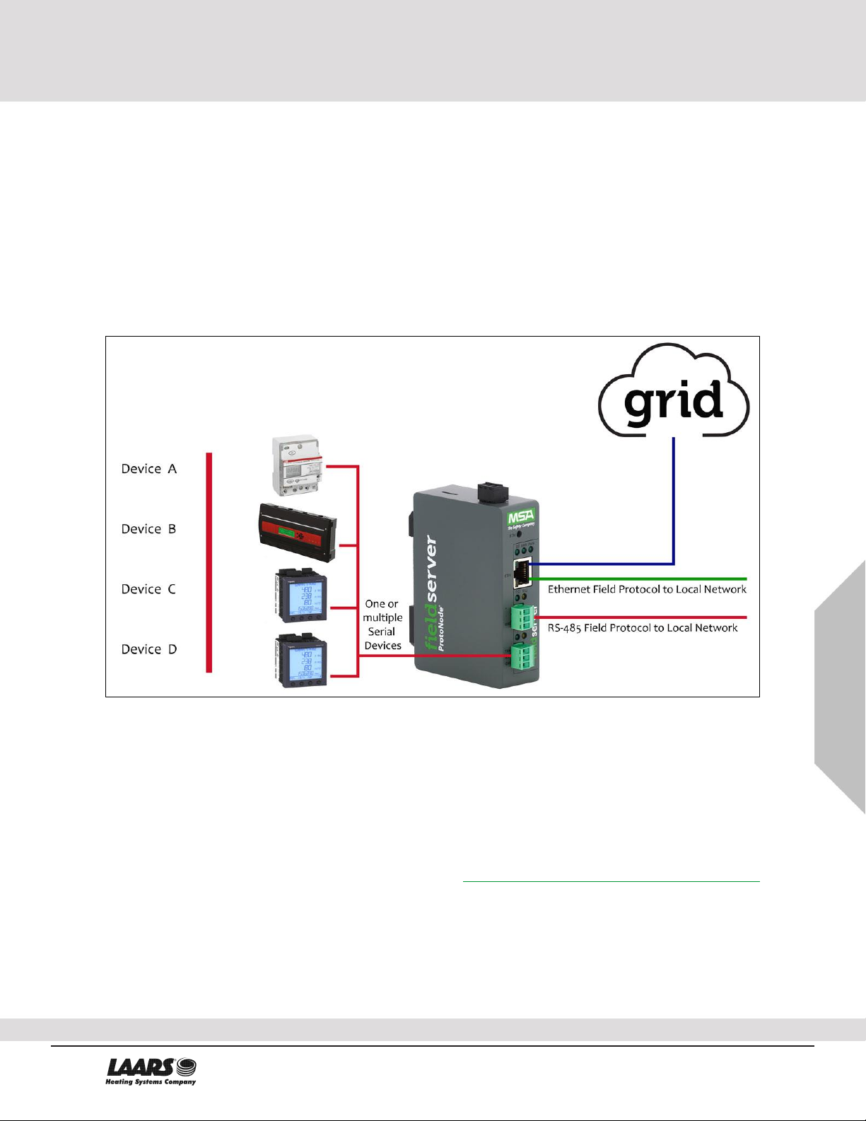
Figure 5: RS-485 Connections from Devices to the ProtoNode..........................................................................11
Figure 6: Connection from ProtoNode to RS-485 Field Network ........................................................................11
Figure 7: Bias Resistor DIP Switches .................................................................................................................12
Figure 8: Termination Resistor DIP Switch .........................................................................................................13
Figure 9: Required Current Draw for the ProtoNode...........................................................................................14
Figure 10: Power Connections ............................................................................................................................14
Figure 11: Ethernet Port Location .......................................................................................................................15
Figure 12: Web Server Security Window ............................................................................................................16
Figure 13: Connection Not Private Warning........................................................................................................16
Figure 14: Warning Expanded Text ....................................................................................................................17
Figure 15: FieldServer Login ...............................................................................................................................17
Figure 16: Security Mode Selection Screen........................................................................................................18
Figure 17: Security Mode Selection Screen –Certificate & Private Key.............................................................19
Figure 18: Generic Web App Landing Page ....................................................................................................... 20
Figure 19: Settings Tabs .....................................................................................................................................20
Figure 20: Registration Warning Window............................................................................................................20
Figure 21: ETH 1 Port Network Settings .............................................................................................................21
Figure 22: Routing Network Settings ..................................................................................................................22
Figure 23: Generic Web App Page –First Login ................................................................................................23
Figure 24: FieldServer Manager Opt Out Warning Window................................................................................24
Figure 25: Welcome to the MSA Grid –FieldServer Manager Email..................................................................25
Figure 26: Setting User Details ...........................................................................................................................26
Figure 27: FieldServer Manager Registration Message......................................................................................27
Figure 28: FieldServer Manager Registration –Installer Details.........................................................................28
Figure 29: FieldServer Manager Registration –Site Details ...............................................................................28
Figure 30: FieldServer Manager Registration –Gateway Details .......................................................................29
Figure 31: FieldServer Manager Registration –Account ....................................................................................29
Figure 32: Device Registered for the FieldServer Manager................................................................................30
Figure 33: FieldServer Manager Login Page ......................................................................................................31
Figure 34: FieldServer Manager Landing Page .................................................................................................. 32
Figure 35: Web App Landing Page ..................................................................................................................... 33
Figure 36: Configure Tab ....................................................................................................................................33
Figure 37: Web Configurator Showing Configuration Parameters ......................................................................34
Figure 38: Web Configurator Showing no Active Profiles ...................................................................................35
Figure 39: Web Configurator Showing Active Profile Additions ..........................................................................36
Figure 40: Web Configurator Node Offset Field ..................................................................................................37
Figure 41: Active Profiles ....................................................................................................................................37
Figure 42: Ethernet Port Location .......................................................................................................................39
Figure 43: Error Messages Screen ..................................................................................................................... 40
Figure 44: Diagnostic LEDs ................................................................................................................................42
Figure 45: Web Configurator –Network Number Field ....................................................................................... 45
Figure 46: DIN Rail..............................................................................................................................................46
Figure 47: ProtoNode FPC-N54 Dimensions ...................................................................................................... 47
Figure 48: FS-GUI Page .....................................................................................................................................48
Figure 49: FS-GUI Security Setup ...................................................................................................................... 49
Figure 50: FS-GUI Security Setup –Certificate Loaded .....................................................................................50
Figure 51: FS-GUI User Management ................................................................................................................ 51
Figure 52: Create User Window ..........................................................................................................................52
Figure 53: Setup Users .......................................................................................................................................53
Figure 54: Edit User Window ..............................................................................................................................53
Figure 55: Setup Users .......................................................................................................................................54
Figure 56: User Delete Warning.......................................................................................................................... 54
LAARS Heating Systems
20 Industrial Way, Rochester, NH, USA 03867 •(800) 900-9276 • www.Laars.com

Page 7 of 72
7
LAARS ProtoNode Start-up Guide 7
Figure 57: FieldServer Password Update via FS-GUI ........................................................................................55
Figure 58: FieldServer Manager Connection Problems Message ......................................................................56
Figure 59: Specifications.....................................................................................................................................59
20 Industrial Way, Rochester, NH, USA 03867 •(800) 900-9276 • www.Laars.com
Gateway Installation and Operating Manual

Page 8 of 72
8
Description
LAARS ProtoNode Start-up Guide 8
1 Introduction
1.1 ProtoNode Gateway
The ProtoNode wireless gateway is an external, high performance building automation multi-protocol
gateway that is preconfigured to automatically communicate between LAARS’devices (hereafter simply
called “device”) connected to the ProtoNode and automatically configures them for BACnet/IP, BACnet
MS/TP, Modbus TCP/IP and Metasys N2.
It is not necessary to download any configuration files to support the required applications. The ProtoNode
is pre-loaded with tested profiles/configurations for the supported devices.
FPC-N54 Connectivity Diagram:
The ProtoNode can connect with the MSA Grid –FieldServer Manager. The FieldServer Manager allows
technicians, the OEM's support team and MSA Safety's support team to remotely connect to the ProtoNode.
The FieldServer Manager provides the following capabilities for any registered devices in the field:
•Remotely monitor and control devices.
•Collect device data and view it on the Dashboard and the MSA Smart Phone App.
•Create user defined device notifications (alarm, trouble and warning) via SMS and/or Email.
•Generate diagnostic captures (as needed for troubleshooting) without going to the site.
For more information on the FieldServer Manager, see the MSA Grid - FieldServer Manager Start-up Guide.
LAARS Heating Systems
20 Industrial Way, Rochester, NH, USA 03867 •(800) 900-9276 • www.Laars.com

Page 9 of 72
9
Installing the Gateway
LAARS ProtoNode Start-up Guide 9
2 Setup for ProtoNode
2.1 Record Identification Data
Each ProtoNode has a unique part number located on the side or the back of the unit. This number should
be recorded, as it may be required for technical support. The numbers are as follows:
Model Part Number
ProtoNode FPC-N54-2061
Figure 1: ProtoNode Part Numbers
•FPC-N54 units have the following 3 ports: RS-485 + Ethernet + RS-485/RS-232
2.2 Point Count Capacity and Registers per Device
The total number of registers presented the device(s) attached to the ProtoNode cannot exceed:
Part number Total Registers
FPC-N54-2061
1,500
Figure 2: Supported Point Count Capacity
Devices Points Per Device
Sola
88
Multiburner
149
SV2
82
HTD
254
OmniTherm
174
MagnaTherm
174
Figure 3: Points per Device
20 Industrial Way, Rochester, NH, USA 03867 •(800) 900-9276 • www.Laars.com
Gateway Installation and Operating Manual

Page 10 of 72
10
Installing the Gateway
LAARS ProtoNode Start-up Guide 10
2.3 Configuring Device Communications
2.3.1 Confirm the Device and ProtoNode COM Settings Match
•Any connected serial devices MUST have the same baud rate, data bits, stop bits, and
parity settings as the ProtoNode.
•Figure 4 specifies the device serial port settings required to communicate with the ProtoNode.
Port Setting Device
Protocol Modbus RTU
Baud Rate 38400
Parity None
Data Bits 8
Stop Bits 1
Figure 4: COM Settings
2.3.2 Set Node-ID for Any Device Attached to the ProtoNode
•Set Node-ID for any device attached to ProtoNode. The Node-ID needs to be uniquely assigned
between 1 and 255.
•Document the Node-ID that is assigned. The Node-ID assigned is used for deriving the Device
Instance for BACnet/IP and BACnet MS/TP. (Section 8.3)
NOTE: The Metasys N2 and Modbus TCP/IP field protocol Node-ID is automatically set to be the
same value as the Node-ID of the device.
LAARS Heating Systems
20 Industrial Way, Rochester, NH, USA 03867 •(800) 900-9276 • www.Laars.com

Page 11 of 72
11
Installing the Gateway
LAARS ProtoNode Start-up Guide 11
3 Interfacing ProtoNode to Devices
3.1 Device Connections to ProtoNode
The ProtoNode has a 3-pin Phoenix connector for connecting RS-485 devices on the R1 port.
NOTE: Use standard grounding principles for RS-485 GND.
Device Pins ProtoNode
Pin Label
Pin
Assignment
RS-485 +
TX +
RS-485 +
RS-485 -
RX -
RS-485 -
RS-485 GND
GND
RS-485 GND
3.2 Wiring Field Port to RS-485 Serial Network
•Connect the RS-485 network wires to the 3-pin RS-485 connector on the R2 port. (Figure 6)
oUse standard grounding principles for RS-485 GND
•See Section 4for information on connecting to an Ethernet network.
BMS
Wiring
ProtoNode
Pin Label
Pin
Assignment
RS-485 +
+
RS-485 +
RS-485 -
-
RS-485 -
-
GND
RS-485 GND
Figure 5: RS-485 Connections from Devices to the ProtoNode
Figure 6: Connection from ProtoNode to RS-485 Field Network
G
-
+
G
-
+
20 Industrial Way, Rochester, NH, USA 03867 •(800) 900-9276 • www.Laars.com
Gateway Installation and Operating Manual

Page 12 of 72
12
Installing the Gateway
LAARS ProtoNode Start-up Guide 12
3.3 Bias Resistors
To enable Bias Resistors, move both the BIAS- and BIAS+ dip switches to the right as shown in
Figure 7.
The ProtoNode bias resistors are used to keep the RS-485 bus to a known state, when there is no
transmission on the line (bus is idling), to help prevent false bits of data from being detected. The bias
resistors typically pull one line high and the other low - far away from the decision point of the logic.
The bias resistor is 510 ohms which is in line with the BACnet spec. It should only be enabled at one
point on the bus (for example, on the field port were there are very weak bias resistors of 100k). Since
there are no jumpers, many gateways can be put on the network without running into the bias resistor
limit which is < 500 ohms.
NOTE: See www.ni.com/support/serial/resinfo.htm for additional pictures and notes.
NOTE: The R1 and R2 DIP Switches apply settings to the respective serial port.
NOTE: If the gateway is already powered on, DIP switch settings will not take effect unless the
unit is power cycled.
R1 Bias Resistor DIP
Switches (2 and 3)
Figure 7: Bias Resistor DIP Switches
R2 Bias Resistor DIP
Switches (2 and 3)
LAARS Heating Systems
20 Industrial Way, Rochester, NH, USA 03867 •(800) 900-9276 • www.Laars.com

Page 13 of 72
13
Installing the Gateway
LAARS ProtoNode Start-up Guide 13
3.4 Termination Resistor
If the ProtoNode is the last device on the serial trunk, then the End-Of-Line Termination Switch needs to
be enabled. To enable the Termination Resistor, move the TERM dip switch to the right as shown in
Figure 8.
Termination resistor is also used to reduce noise. It pulls the two lines of an idle bus together. However,
the resistor would override the effect of any bias resistors if connected.
NOTE: The R1 and R2 DIP Switches apply settings to the respective serial port.
NOTE: If the gateway is already powered on, DIP switch settings will not take effect unless the
unit is power cycled.
R1 Termination
Resistor DIP Switch (1)
Figure 8: Termination Resistor DIP Switch
R2 Termination
Resistor DIP Switch (1)
20 Industrial Way, Rochester, NH, USA 03867 •(800) 900-9276 • www.Laars.com
Gateway Installation and Operating Manual

Page 14 of 72
14
Installing the Gateway
LAARS ProtoNode Start-up Guide 14
3.5 Power-Up ProtoNode
Check power requirements in the table below:
Power Requirement for ProtoNode External Gateway
Current Draw Type
ProtoNode Family
12VDC
24VDC/AC
FPC –N54 (Typical)
250mA
125mA
NOTE: These values are ‘nominal’ and a safety margin should be added to the power supply of
the host system. A safety margin of 25% is recommended.
Figure 9: Required Current Draw for the ProtoNode
Apply power to the ProtoNode as shown below in Figure 10. Ensure that the power supply used complies
with the specifications provided in Section 12.
•The ProtoNode accepts 9-30VDC or 24VAC on pins L+ and N-.
•Frame GND should be connected.
Power to
ProtoNode
ProtoNode
Pin Label
Pin
Assignment
Power In (+)
L +
V +
Power In (-)
N -
V -
Frame Ground
FG
FRAME GND
Figure 10: Power Connections
LAARS Heating Systems
20 Industrial Way, Rochester, NH, USA 03867 •(800) 900-9276 • www.Laars.com

Page 15 of 72
15
Setup Web Server Security
LAARS ProtoNode Start-up Guide 15
4 Connect the PC to the ProtoNode
4.1 Connecting to the Gateway via Ethernet
Connect a Cat-5 Ethernet cable (straight through or cross-over) between the local PC and ProtoNode.
4.1.1 Changing the Subnet of the Connected PC
The default IP Address for the ProtoNode is 192.168.1.24, Subnet Mask is 255.255.255.0. If the PC and
ProtoNode are on different IP networks, assign a static IP Address to the PC on the 192.168.1.xxx network.
For Windows 10:
•Find the search field in the local computer’s taskbar (usually to the right of the windows icon )
and type in “Control Panel”.
•Click “Control Panel”, click “Network and Internet” and then click “Network and Sharing Center”.
•Click “Change adapter settings” on the left side of the window.
•Right-click on “Local Area Connection” and select “Properties” from the dropdown menu.
•Highlight and then click the Properties button.
•Select and enter a static IP Address on the same subnet. For example:
•Click the Okay button to close the Internet Protocol window and the Close button to close the
Ethernet Properties window.
Ethernet Port
Figure 11: Ethernet Port Location
20 Industrial Way, Rochester, NH, USA 03867 •(800) 900-9276 • www.Laars.com
Gateway Installation and Operating Manual

Page 16 of 72
16
Setup Web Server Security
LAARS ProtoNode Start-up Guide 16
5 Setup Web Server Security
Navigate to the IP Address of the ProtoNode on the local PC by opening a web browser and entering the
IP Address of the ProtoNode; the default Ethernet address is 192.168.1.24.
NOTE: If the IP Address of the ProtoNode has been changed, the assigned IP Address can be
discovered using the FS Toolbox utility. See Section 9.1 for instructions.
5.1 Login to the FieldServer
The first time the FieldServer GUI is opened in a browser, the IP Address for the gateway will appear as
untrusted. This will cause the following pop-up windows to appear.
•When the Web Server Security Unconfigured window appears, read the text and choose whether
to move forward with HTTPS or HTTP.
•When the warning that “Your connection is not private” appears, click the advanced button on the
bottom left corner of the screen.
Figure 13: Connection Not Private Warning
Figure 12: Web Server Security Window
LAARS Heating Systems
20 Industrial Way, Rochester, NH, USA 03867 •(800) 900-9276 • www.Laars.com

Page 17 of 72
17
Setup Web Server Security
LAARS ProtoNode Start-up Guide 17
•Additional text will expand below the warning, click the underlined text to go to the IP Address. In
the Figure 14 example this text is “Proceed to 10.40.50.94 (unsafe)”.
•When the login screen appears, put in the Username (default is “admin”) and the Password (found
on the label of the FieldServer).
NOTE: There is also a QR code in the top right corner of the FieldServer label that shows the
default unique password when scanned.
NOTE: A user has 5 attempts to login then there will be a 10-minute lockout. There is no timeout
on the FieldServer to enter a password.
NOTE: To create individual user logins, go to Section 10.7.
Figure 14: Warning Expanded Text
Figure 15: FieldServer Login
20 Industrial Way, Rochester, NH, USA 03867 •(800) 900-9276 • www.Laars.com
Gateway Installation and Operating Manual

Page 18 of 72
18
Setup Web Server Security
LAARS ProtoNode Start-up Guide 18
5.2 Select the Security Mode
On the first login to the FieldServer, the following screen will appear that allows the user to select which
mode the FieldServer should use.
NOTE: Cookies are used for authentication.
NOTE: To change the web server security mode after initial setup, go to Section 10.1.
The sections that follow include instructions for assigning the different security modes.
Figure 16: Security Mode Selection Screen
LAARS Heating Systems
20 Industrial Way, Rochester, NH, USA 03867 •(800) 900-9276 • www.Laars.com

Page 19 of 72
19
Setup Web Server Security
LAARS ProtoNode Start-up Guide 19
5.2.1 HTTPS with Own Trusted TLS Certificate
This is the recommended selection and the most secure. Please contact your IT department to find out
if you can obtain a TLS certificate from your company before proceeding with the Own Trusted TLS
Certificate option.
•Once this option is selected, the Certificate, Private Key and Private Key Passphrase fields will
appear under the mode selection.
•Copy and paste the Certificate and Private Key text into their respective fields. If the Private Key is
encrypted type in the associated Passphrase.
•Click Save.
•A “Redirecting” message will appear. After a short time, the FieldServer GUI will open.
5.2.2 HTTPS with Default Untrusted Self-Signed TLS Certificate or HTTP with Built-in
Payload Encryption
•Select one of these options and click the Save button.
•A “Redirecting” message will appear. After a short time, the FieldServer GUI will open.
Figure 17: Security Mode Selection Screen –Certificate & Private Key
20 Industrial Way, Rochester, NH, USA 03867 •(800) 900-9276 • www.Laars.com
Gateway Installation and Operating Manual

Page 20 of 72
20
Configuring the Gateway
LAARS ProtoNode Start-up Guide 20
6 Configure Network Settings
6.1 Navigate to the Settings
•From the Web App landing page, click the Settings tab on the left side of the screen.
•Click the Network tab that appears to open the Network Settings page.
•A warning message will appear when performing the first-time setup, click the Exit Registration
button to continue to the Settings page.
Figure 18: Generic Web App Landing Page
Figure 19: Settings Tabs
Figure 20: Registration Warning Window
LAARS Heating Systems
20 Industrial Way, Rochester, NH, USA 03867 •(800) 900-9276 • www.Laars.com
Table of contents
Other Laars Industrial Equipment manuals