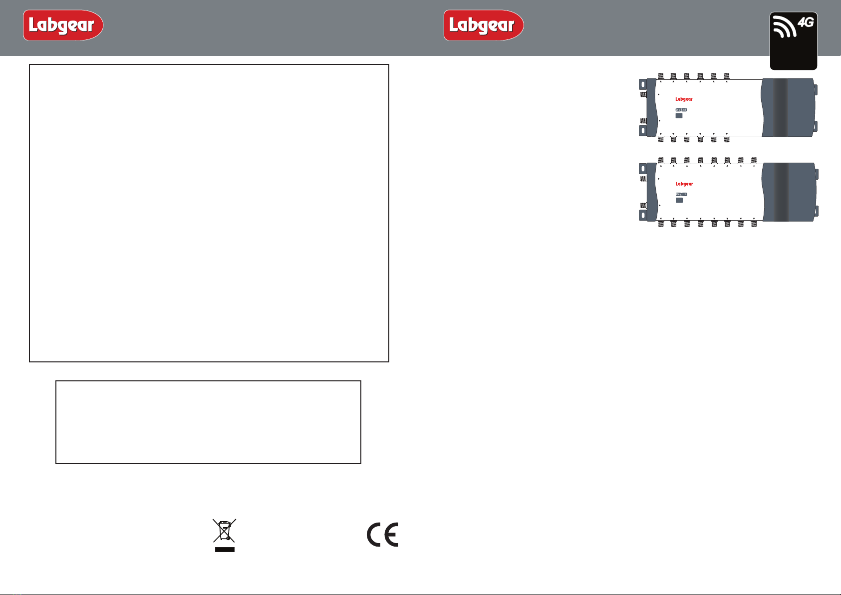
LDL212 - 12 Way Digilink Amplifier
LDL216 - 16 Way Digilink Amplifier
(distribution amps with DigiLink IR return paths)
For further information or any queries please contact
Customer Careline: 08457 573 479
(Local rate – UK only)
Technical Support: www.philex.com/support
2 –Year Guarantee
Your amplifier is guaranteed against faulty components or poor workmanship for a
period of two years from the date of purchase.
This guarantee does not cover accidental or malicious damage (Including damage from
natural causes such as lightening) and will be invalidated by installation or use other
than in accordance with these instructions, repair or attempted repair other than by the
manufacturer, or open or removal of the case.This does affect your statutory rights.
Labgear Reserve the right to modify their designs or specifications, In the light of future
developments, without prior notice.Performance figures quoted are typical and subject
to normal manufacturing and service tolerances
Installation Instructions
Introduction
These fully screened 12 and 16 way TV and
FM/DAB amplifiers are fully compatible with
Labgear DigiLink remote control systems.
This makes them ideal for use in digital satellite
home installations, where the output from a
digibox can be distributed to several rooms with
the capability for full remote control of the box
for any room on the system.
The addition of a number of MRX955 DigiLink
remote‘eyes’in the relevant rooms completes
the installation. Alternatively the products may
be used as traditional ‘aerial amplifiers’without
making use of the infrared capability.
Separate inputs are provided for UHF TV (470-790 MHz) and for FM/DAB (88-230 MHz).
Remote capability is provided over a 5-15 MHz RF return path.
All amplifier outputs are line powered at 9V DC to supply remote infra-red receivers.The line
power at any output(s) can be short-circuited safely, without affecting the operation of any
other output(s).
Both units are also suitable for direct amplication of digital terrestrial TV (Freeview™) signals
and the UHF input can be connected directly to a UHF antenna instead of a satellite receiver.
When connected directly to a UHF aerial a built in lter removes any signals from Lte 800 4G
mobile phone transmitters picked up by the attached aerial.
Please Note: These amplifiers are NOT COMPATIBLE with the Labgear Handylink Remote
control extender system (MRX120).These amplifiers do not provide line-power for masthead
preamplifiers.
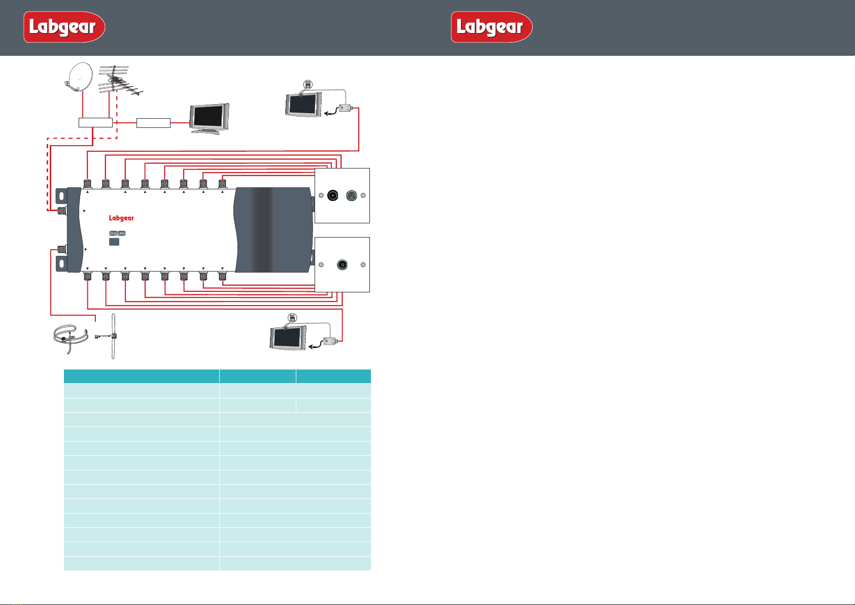
Applications - Example application diagram is shown on page 2.
Applications include the following:
• Simple multipoint distribution of radio and TV signals, without remote control.
This will allow quick and easy addition of an IR control at a later date;
• Use in conjunction with a Sky Digibox or other unit with an IR-return enabled RF output.
An MRX955 DigiLink room kit will be required for each room from which remote control
is needed (because the Digibox can decode the IR return signals directly, this application
does not require any base unit or IR re-emitters).
Please Note: when using these amplifiers with a Sky Digibox, the amplifier must be fed from
RF OUT-2 socket of the Digibox. However if the RF Channel is set to 61 or above (68 is usually
the default channel) you will need to reset it to a channel from 21-60 in the Digibox Setup
Menu (see bottom of page 3). Later Digibox models such as the Sky+HD 2TB are not fitted
with an RF OUT2 output and you will need an I/O link to distribute signals from the Digibox
to other TVs.
General Safety Precautions
To Prevent Overheating
The recommended clearances and other precautions given in these instructions must be
observed to prevent overheating.In addition, units should not be positioned where they
are likely to become covered by curtains/fabrics or thermal insulation materials in a roof
space or similar building void. The unit should not be left resting on a carpet.
Other Precautions
These appliances are not waterproof. They are for indoor use only and must not be posi-
tioned where they could be exposed to dripping or splashing water. Objects containing
liquids should not be placed on or near the appliance.To prevent risk of fire, keep the
unit and attached wiring well away from naked flames.
Fitted Mains Plug
These appliances are supplied with a standard fixed plug already fitted. If this is not
suitable, refer to the instructions below. If you need to change the fuse in this plug,
a 3Amp fuse to BS1362 carrying the ASTA or BSI approved mark must be used.
Always re-fit the plastic fuse carrier when replacing the fuse.
Changing the Plug
If the fitted mains plug is not suitable for the socket outlet in use, it should be cut off
and an appropriate new plug fitted. Any instruction supplied with the plug should be
followed.The Brown wire must be connected to the live (L) terminal of the plug and the
Blue wire to the neutral (N) terminal. Neither wire should be connected to the earth (E)
terminal of a 3-pin plug (this appliance does not require an earth connection). Ensure
that the cord grip in the plug is correctly used and clamps the sheath of the cord firmly.
Fuse Rating: If the new plug is a fused type, the fuse fitted should be rated at no more
than 3 Amp. Caution:The old plug should be disposed of promptly since it would be
dangerous if plugged into a live socket.
41
Installation Instructions
OUT 10 OUT 11OUT 9OUT 8OUT 7
OUT 1 OUT 2 OUT 6OUT 5OUT 4OUT 3
FM/DAB
12-way Distribution Amplifier
UHF
OUT 12
LDL212
Lte
800
READY
Frequency: UHF 470-790MHz
FM/DAB 47-230MHz
Gain: 10dB
Noise: 3.5dB
Return path: 5-15MHz with Insertion Loss 2dB
DigiLink power: 9V DC on each outlet, 15mA
OUT 8OUT 7
OUT 15 OUT 16
OUT 12 OUT 13OUT 11OUT 10OUT 9
OUT 1 OUT 2 OUT 6OUT 5OUT 4OUT 3
FM/DAB
16-way Distribution Amplifier
UHF
OUT 14
LDL216
Lte
800
READY
Frequency: UHF 470-790MHz
FM/DAB 47-230MHz
Gain: 10dB
Noise: 3.5dB
Return path: 5-15MHz with Insertion Loss 2dB
DigiLink power: 9V DC on each outlet, 15mA
Lte
800
READY
Waste electrical products should not
be disposed of with household waste.
Please recycle where facilities exist.
Check with your Local Authority for
recycling advice.
© Philex Electronic Ltd. 2013 V1