Labounty MDG Series Guide

MOBILE DEMOLITION GRAPPLE
Safety, Operation & Maintenance
515933 User Manual 7/2018 Ver. 3
MDG
LaBounty | 1538 Hwy 2 | Two Harbors, MN 55616 | 1-800-522-5059 | www.stanleyinfrastructure.com/brands/labounty
www.stanleyinfrastructure.com/brands/labounty

2 | MDG Operating & Maintenance Manual
This manual contains information for the operation and maintenance of the LaBounty MDG Mobile Demolition Grapple.
Read the entire manual before the initial start-up of the attachment. It is important to know the correct operating
procedures of the attachment and all safety precautions to prevent the possibility of property damage and personal
injury.
The LaBounty attachment has been designed and manufactured with high quality materials and care in workmanship.
The instructions in this manual have been prepared to ensure that, when followed properly, the attachment will provide
ecient and reliable service. Continuing product development and improvement may have caused changes in the
attachment that are not reected in this manual. If a question arises regarding the operation or maintenance of the
attachment, contact a LaBounty dealer for the most current information available.
IMPORTANT
This operator’s manual must accompany the attachment at all times and be readily available to the operator.
MANUAL REPLACEMENT
Should this manual become damaged, lost or additional copies are required, immediately contact any authorized
LaBounty dealer. You may also download a PDF copy at www.stanleyinfrastructure.com.
REGISTRATION FORM
The Warranty Registration Form must be lled out by the dealer or customer and returned to LaBounty indicating the
date the machine went into service.
POSSIBLE VARIATIONS
LaBounty cannot anticipate every possible circumstance that might involve a potential hazard, as the owner’s
requirements and equipment may vary. Therefore, the warnings in this publication and on the product may not be all-
inclusive and you must ensure that the procedure, application, work method and operating technique is safe for you,
and others, before operation.
PUBLIC NOTICE
LaBounty reserves the right to make changes and improvements to its products and technical literature at any time,
without public notice or obligation. LaBounty also reserves the right to discontinue manufacturing any product at its
discretion, at any time.
WARRANTY
All work or repairs to be considered for warranty reimbursement must be authorized by the LaBounty Service
Department before work is started. Any alterations, modications or repairs performed before authorization by the
LaBounty Service Department will render all warranty reimbursement consideration null and void without exception.
Improper operation or improperly performed maintenance may render any warranty null and void.
PREFACE

MDG Operating & Maintenance Manual | 3
CONTENTS
SAFETY .....................................................................................................4
DECLARATION OF CONFORMITY ..........................................................6
DECALS & TERMS ....................................................................................7
INSTALLATION .........................................................................................8
Hydraulic Installation ...........................................................................................................................................................8
Hydraulic Circuit Requirements.......................................................................................................................................8
Removing MDG from the Excavator...............................................................................................................................9
Storing MDG ...........................................................................................................................................................................9
OPERATION ...............................................................................................10
Before You Start ....................................................................................................................................................................10
Safety Devices ......................................................................................................................................................................10
Technical Specications ....................................................................................................................................................11
Controls....................................................................................................................................................................................11
Bleed the Hydraulic Circuit................................................................................................................................................11
Operating Tips .......................................................................................................................................................................11
MAINTENANCE ........................................................................................12
Daily Before Use Inspection Checklist..........................................................................................................................12
8-Hour Inspection Checklist.............................................................................................................................................12
Hydraulic Inspection............................................................................................................................................................13
Inspect / Torque Bolts .........................................................................................................................................................13
Replace Wear Blades...........................................................................................................................................................13
Lubrication...............................................................................................................................................................................14
Rotation Head Lubrication.................................................................................................................................................15
PARTS DIAGRAMS...................................................................................16
MDG70 Exploded View .......................................................................................................................................................16
MDG70 Parts List..................................................................................................................................................................17
MDG140 Exploded View.....................................................................................................................................................18
MDG140 Parts List ...............................................................................................................................................................19
MDG160, 250, 310 & 400 Exploded View....................................................................................................................20
MDG160, 250, 310 & 400 Parts List...............................................................................................................................21
MDG70 & 140 Cylinder parts List ...................................................................................................................................23
MDG160, 250, 310 & 400 Right Cylinder parts List .................................................................................................24
MDG160, 250, 310 & 400 Left Cylinder parts List....................................................................................................25
MDG70 Swivel parts List....................................................................................................................................................26
MDG140 ,160, 250, 310 & 400 Swivel parts List.......................................................................................................27

4 | MDG Operating & Maintenance Manual
SAFETY
Your safety and the safety of others
is a direct result of how you operate
and maintain your equipment. Read
and understand this manual and other
safety information provided with the
base machine and be sure that you
understand all controls and operating
instructions before attempting to operate this equipment.
Failure to follow the safety precautions can result in
personal injury, death or property damage.
Carefully read all safety messages in this manual and on
your equipment safety decals to reduce the risk of injury.
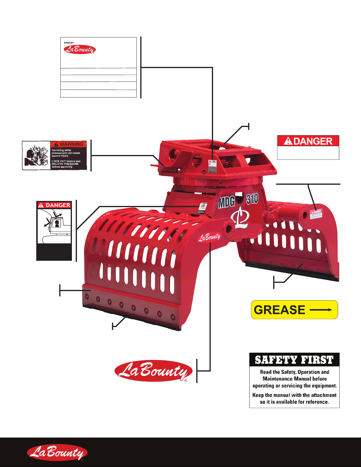
Keep safety decals in good condition. Replace missing or
damaged safety decals. Failure to follow the warnings and
instructions may result in serious injury or damage to the
tool.
Because LaBounty cannot foresee all hazardous
circumstances, the precautions listed in this manual and
on the equipment are not all-inclusive. If a procedure,
method, tool or part is not specically recommended by
LaBounty, determine whether it is safe for you and others,
and that the equipment will not be damaged or made
unsafe as a result of your decision to implement it.
The basic rules are summarized in this section of the
manual. They also appear throughout the manual along
with additional specic rules for safety and operation.
• Wear personal protection equipment. This includes
eye protection, hard hat, steel toe shoes, gloves,
hearing protection and respirator.
• Use PPE that conforms to standards ANSI Z87.1 (Eye
and Face Protection), ANSI Z89.1 (Head Protection)
and ANSIZ41.1 (Foot Protection).
• If the attachment is not functioning properly, shut
down the machine, follow proper lockout / tag out
procedures and follow proper repair procedures.
• NEVER operate equipment without the original safety
guards in place.
• Ensure that the cab is equipped with the proper
safety guards for LaBounty applications. The cab
MUST be equipped with an approved Falling Object
Protection Structure (FOPS). The FOPS must
meet the requirements of SAE standard J1356. A
transparent, shatter-resistant shield covering the
front of the cab, is also required. Contact your base
machine equipment dealer or manufacturer for more
information on the availability of FOPS. Lack of proper
FOPS may result in injury or death.
• NEVER operate the excavator without a proper
restraint (seat belt) system in place. Doing so can
create loss of control or ejection from cab.
• NEVER operate the equipment while under the
inuence of drugs, alcohol or other substances that
inhibit mental abilities or reaction time.
• DO NOT process material with the attachment over
the operator’s cab. Doing so will result in severe
personal injury or death from falling debris.
• NEVER remove any pins unless the attachment is
on the ground and blocked up, or serious injury or
death could result. Metal chips or debris may y when
a connecting pin is struck. Use a brass drift when
striking pins and always wear protective clothing and
proper eye protection.
• Clear all persons and equipment from the area of
operation and machine movement. NEVER move
loads over people or equipment. When viewing the
operation of the attachment, maintain a safe distance
of at least 75 feet (23 meters).
• NEVER approach power lines with any part of the
machine. Keep clear at a minimum of 50 feet (16
meters).
• DO NOT close the attachment on a structure and
reverse the excavator in an attempt to pull down
material.
• Avoid tipping. The attachment will alter the lift
capacities of the base machine. DO NOT overload
the excavator or serious injury could result. Lift
capacities will vary if the base machine is not on level
ground. Lifting incorrectly can cause severe injury or
machine damage. Use the recommended excavator
counterweight. Use short slings and lift the load only
as high as necessary.

MDG Operating & Maintenance Manual | 5
• Use of this tool on certain materials could generate
dust potentially containing a variety of hazardous
substances, such as, asbestos, silica or lead.
Inhalation of dust containing these, or other
hazardous substances could result in serious injury,
cancer or death. Protect yourself and those around
you. Research and understand the materials you are
processing. Follow safety procedures and comply
with all applicable national, state or provisional health
and safety regulations relating to them. If appropriate,
arrange for the safe disposal of the materials by a
qualied person.
• NEVER modify or mount the attachment to a carrier
other than the one it was originally designed for.
Rotation component failure may result, causing the
attachment to fall to the ground.
‘
• Remove all hydraulic and electrical power from
the excavator before installing or maintaining the
attachment.
• ALWAYS lower the boom to the ground before leaving
the cab. If it is necessary to work on an attachment
o the ground, securely support the machine and
attachment. DO NOT support the machine on cinder
blocks, hollow tiles, or props that may crumble under
continuous load. DO NOT rely on a cylinder to hold the
attachment in the air. DO NOT work under a machine
that is supported only by a jack.
• DO NOT let hot hydraulic oil come in contact with the
skin, as it could cause severe burns. Wear adequate
protective clothing and safety equipment. DO NOT
tamper with any hydraulic line or component while
it is pressurized. Escaping uid under pressure can
penetrate the skin, causing serious injury. Relieve
pressure before unhooking hydraulic or other lines.
Tighten all connections before applying pressure.
Keep hands and body away from pinholes and nozzles
which eject uid under high pressure. Use a piece of
cardboard to search for leaks. If ANY uid is injected
into the skin, seek immediate medical assistance.
• Use protective clothing and safety devices
appropriate for the working conditions at all
times when viewing, operating or maintaining the
attachment. These may include, but are not limited to,
close-tting clothing, eye protection, hard hat, steel
toe shoes, gloves, hearing protection and respirator
protection
• Keep clear of all potential pinch points, including the
moving grapple halves, cylinder connections, bucket
linkages and other moving parts.
• DO NOT weld on any structural member unless
specically authorized by LaBounty. Any unauthorized
welding or welding procedures will void the warranty,
and may cause structural failure or result in personal
injury.
• Check ground conditions. Avoid unstable or slippery
areas. Position the excavator on rm, level ground. If
level ground is not possible, position the excavator
to use the attachment from the front or back. Avoid
working over the side of the excavator.
• Never leave equipment unattended with the engine
running or with the attachment in a raised position.
• Do not operate poorly maintained or otherwise faulty
equipment. Inform the proper authority and DO NOT
operate until xed.

6 | MDG Operating & Maintenance Manual
DECLARATION OF CONFORMITY
EC DECLARATION OF CONFORMITY
EG KONFORMITATSERKLARUNG
DECLARATION CE DE CONFORMITE
DECLARATION CE
DE CONFORMIDAD
DICHIARAZIONE CE
DI CONFORMITA
_
We:
Wir:
Je soussigné:
El abajo firmante:
lo sottoscritto:
Stanley Hydraulic Tools/LaBounty
1538 Highway 2, Two Harbors, MN 55616, USA
hereby declare that the machine specified hereunder:
bestätige hiermit, dassß die nachfolgend beschriebene Maschine:
déclare que l’équipement visé ci-dessous:
Por la presente declaro que el equipo se especifica a continuación:
Dichiaro che le apparecchiature specificate di seguito:
1. Category: Excavator Mounted Demolition Grapple
Kategorie:
Catégorie:
Categoria:
Categoria:
2. Make/Marke/Marque/Marca/Marca LaBounty / Stanley
3. Type/Typ/Type/Tipo/Tipo: MDG70, MDG140, MDG160, MDG250. MDG310, MDG400
4. Serial number of equipment:
Seriennummer des Geräts:
Numéro de série de l’équipement:
Numero de serie del equipo:
Matricola dell´attrezzatura:
SN: MDG
Has been manufactured in conformity with
Wurde hergestellt in Übereinstimmung mit
Est fabriqué conformément
Ha sido fabricado de acuerdo con
E’stata costruita in conformitá con
Directive/Standards
Richtlinie/Standards
Directives/Normes
Directriz/Los Normas
Direttiva/Norme
No.
Nr
Numéro
No
n.
Details:
EN
Machinery Directive
12100:2010
2006/42/EC:
This Directive applies to Interchangeable Machinery. ‘Interchangeable
equipment
’ means a device which, after the putting into service of Machinery
or of a tractor, is assembled with that machinery or tractor by the operator
himself in order to change its function or attribute a new function,
5. Special Provision: For compilation of the technical file the person listed under No. 6 is responsible.
Spezielle Bestimmungen: Für die Zusammenstellung der technischen Unterlagen ist die unter Nr.6 genannte Person verantwortlich
Dispositions particulières: Pour la compilation du dossier technique de la personne inscrite sous le n ° 6 est responsable
Provisiones especiales: Para la compilación del expediente técnico a la persona que aparece bajo el N ° 6 es responsable
Disposizioni speciali: Per la compilazione della scheda tecnica della persona elencato sotto No. 6 è responsabile
6. Representative in the Union: Patrick Vervier, Stanley Dubuis 17-19, rue Jules Berthonneau-BP 3406 41034 Blois Cedex, France.
Vertreter in der Union/Représentant dans l’union/Representante en la Union/Rappresentante presso l’Unione
Done at/Ort/Fait à/Dado en/Fatto a: Stanley Hydraulic Tools/LaBounty, 1538 Highway 2, Two Harbors, Minnesota, USA. 55616
Date/Datum/le/Fecha/Data: 03 / 29 / 2017
Name and Signature/Name und Unterschrift/Signature/Firma/Firma Michael W. Kaczrowski
Position/Position/Fonction/Cargo/Posizione Operations Manager

MDG Operating & Maintenance Manual | 7
RIGHT JAW
SHELL
LEFT JAW
SHELL
WEAR BLADE
ROTATING HEAD
DECALS & TERMS
Top and front cab
guarding required during
any material processing
application
Keep 30 feet (10m)
away during operation
Serial Number Plate
P/N: 511045
FIGURE 1
Pressure Relief
Warning Decal
P/N: 512572
FIGURE 2
Cab Guard Decal
P/N: 503647
FIGURE 3
LaBounty Logo Decal
FIGURE 4
Safety First Decal
(Included w/ manuals)
P/N: 503590
FIGURE 5
Grease Decal
(At each tting)
P/N: 116388
FIGURE 6
Safe Distance Decal
P/N: 503708
FIGURE 7
1538 Highway 2
Two Harbors, MN 55616
tel: 1-800-522-5059
fax: 218-834-3879
www.stanleyhydraulics.com
Made in the U.S.A. with Global Materials
Attachment Model:
Serial Number:
Year of Manufacture:
Weight:

8 | MDG Operating & Maintenance Manual
INSTALLATION
Each MDG is shipped with a custom mounting bracket. Refer to the Parts Manual shipped with the attachment for
specic installation information.
1. Locate at, hard ground (e.g., concrete oor) for installation. Lift and place the attachment on the ground. Use
blocking if necessary.
2. Remove the excavator bucket. Follow the manufacturer’s recommended procedure.
Note: Plug hydraulic hoses to prevent contamination.
3. Install MDG, using the custom mounting bracket, to the excavator arm.
HYDRAULIC INSTALLATION
DO NOT connect hydraulic lines while they are pressurized.
serious injury.
HYDRAULIC CIRCUIT REQUIREMENTS
Model Jaw Cycle Circuit (Max) Rotation Circuit (Max)
MDG 70 13 GPM (50 LPM)
4,350 PSI (300 Bar)
3 GPM (12 LPM)
2,755-3,045 PSI (190-210 Bar)
MDG 140 26 GPM (99 LPM)
5,075 PSI (350 Bar)
7 GPM (27 LPM)
2,755-3,045 PSI (190-210 Bar)
MDG 160 32 GPM (122 LPM)
5,070 PSI (350 Bar)
7 GPM (27 LPM)
2,755-3,045 PSI (190-210 Bar)
MDG 250 42 GPM (159 LPM)
5,070 PSI (350 Bar)
9 GPM (35 LPM)
2,755-3,045 PSI (190-210 Bar)
MDG 310 48 GPM (182 LPM)
5,070 PSI (350 Bar)
9 GPM (35 LPM)
2,755-3,045 PSI (190-210 Bar)
MDG 400 53 GPM (201 LPM)
5,070 PSI (350 Bar)
9 GPM (35 LPM)
2,755-3,045 PSI (190-210 Bar)
1. Connect the hydraulic hoses to the connections located on the rotating head.
2. Torque all hydraulic ttings using the table below.
ORFS Size Hex Nut Size Torque
-8
(0.5 in / 12.7 mm)
15/16 in
(28.8 mm)
52 Ft-Lbs
(95 Nm)
-16
(1 in / 25.4 mm)
1-5/8 in
(41.3 mm)
200 Ft-Lbs
(271 Nm)

MDG Operating & Maintenance Manual | 9
an injection injury occurs
3. Visually check for hydraulic oil leaks or hydraulic hose interference.
REMOVING MDG FROM THE EXCAVATOR
1. Curl the attachment under the boom of the excavator and use blocking to support it.
removing hydraulic hoses or injury or death could result.
2. Carefully remove the hydraulic connections.
Note: Plug hydraulic hoses to prevent contamination.
hazardous. Never remove any pins unless MDG is on the
3. Remove MDG from the mounting bracket (see Parts Manual for details on the custom mounting bracket).
STORING MDG
1. Securely block the attachment o the ground using wood blocking.
2. Plug all open hydraulic ports.
3. Grease MDG as described in “Lubrication” on page 14.

10 | MDG Operating & Maintenance Manual
OPERATION
BEFORE YOU START
Know Your Safety Program
• Read and understand this manual and the base
machine manual.
• Know the employer’s safety rules. Consult your
foreman for instructions and safety equipment.
• Learn the trac rules at the work site. Know the hand
signals used on the job and who is responsible for
signaling. Take signals from only ONE person.
• Wear personal protection equipment. This includes
eye protection, hard hat, steel toe shoes, gloves,
hearing protection and respirator.
Know Your Equipment
• Learn and test the function of all controls. If
malfunctions are found, shut the machine down and
report the malfunction for repair.
• Be familiar with safety devices, indicators, warning
devices and caution instructions. They will alert you to
conditions that are hazardous.
• Know the clearances in the work area.
Daily Safety Checks
• Ensure all decals are installed and legible. Contact
LaBounty for replacements as required.
• Have a DAILY safety dialog with all workers. Inform
them of any abnormal work that is planned. Remind
them of the safe working distance.
• Clear the area. A LWAY S look out for others. In any
work area, people constitute a serious safety hazard.
Before operating, walk around the machine to ensure
no workers are next to, under or on it. Warn nearby
workers that you are starting up. DO NOT start up until
they are out of danger.
• Check the location of cables, gas lines and water
mains before operation. Ensure work site footing has
sucient strength to support the machine. When
working close to an excavation, position machine with
the propel motors at the rear.
• Keep bystanders clear, especially before moving
the boom, swinging the upper structure, or traveling.
A LWAY S be alert for bystanders in or near the
operating area.
SAFETY DEVICES
• Seat belts • Canopies
• Safety decals • Shields and guards
• Flags and ares • Barricades
• Signs and other
markings
• Warning lights
• Falling Objects
Protective Structures
(FOPS)
• Visual or audible
warning devices
General Rules For Safe Operation
• KNOW the capacity of the excavator and it’s
attachments. DO NOT overload or serious injury
could result. The attachment may have altered the
machine’s lift capabilities.
• MDG is for sorting materials. DO NOT use for
unapproved purposes or warranty may be voided.
• If MDG stalls during processing, scale back the
amount of material being processed at one time.
Overloading can cause overheating and has adverse
eects on the hydraulic system.
• Cycle the MDG cylinder completely when processing.
Fully cycling MDG will allow hydraulic uid to circulate
and prevents overheating.
• Maintain a safe distance.
• NEVER leave MDG suspended or pass it over people,
occupied vehicles or buildings.
• When working in conned spaces, keep watch on
exposed parts, such as cylinder rods and hoses, to
avoid damage.
• Maintain at least 50 feet (15 meters) between MDG
and any nearby power lines.
• A LWAY S lower MDG to the ground and turn the base
machine o when leaving the machine unattended.
• DO NOT close the jaws on a structure and reverse
the excavator in an attempt to pull down material. This
is dangerous and will damage the excavator and the
attachment.
• DO NOT alter factory preset hydraulics. This may void
the warranty.
• DO NOT shear high tensile steel, such as railroad
rail, spring steel, axles and some types of wire. Jaw
damage will result. This type of material breaks when
processed and can become a projectile which could
cause injury or death.
• Ensure the connecting pins between the excavator
and the MDG are secured, as well as the wedge and
the security pin of the quick release hitch system.

MDG Operating & Maintenance Manual | 11
TECHNICAL SPECIFICATIONS
Model Min. Excavator Weight MDG Weight Jaw Width Jaw Opening Jaw Capacity
MDG 70 11,000 Lbs
5 mTons
900 Lbs
400 Kg
28 in
710 mm
59 in
1,500 mm
0.3 yds³
0.2 m³
MDG 140 22,000 Lbs
10 mTons
1,900 Lbs
900 Kg
31 in
790 mm
71 in
1,800 mm
0.5 yds³
0.4 m³
MDG 160 29,000 Lbs
13 mTons
2,400 Lbs
1,100 Kg
35 in
890 mm
77 in
1,960 mm
0.8 yds³
0.6 m³
MDG 250 37,000 Lbs
17 mTons
3,300 Lbs
1,500 Kg
39 in
990 mm
83 in
2,110 mm
1.0 yd³
0.8 m³
MDG 310 55,000 Lbs
25 mTons
4,200 Lbs
1,900 Kg
47 in
1,190 mm
87 in
2,210 mm
1.2 yds³
0.9 m³
MDG 400 66,000 Lbs
30 mTons
6,000 Lbs
2,700 Kg
54 in
1,370 mm
87 in
2,210 mm
1.4 yds³
1.1 m³
CONTROLS
Excavator Control MDG Action
Auxiliary Control Opens/Closes Jaws
MDG uses two auxiliary hydraulic circuits. Consult your
distributor for excavator specic installation information.
BLEED THE HYDRAULIC CIRCUIT
Air must be bled out of the hydraulic circuit prior to
operation. Air in the system leads to cavitation, oxidation
of the oil and excessive heat. These conditions promote
hydraulic oil break-down, contamination, noise, sluggish
operation, reduced component life and potential cylinder
damage.
1. Start with MDG in the vertical position.
2. Set the excavator at idle speed.
3. Slowly open the jaws until a noticeable change in tone
of the excavator is heard, indicating a full cylinder.
Release the controls and do not continue to apply full
operating pressure to the cylinder.
4. Slowly close the jaws until the cylinder rod is extended
approximately 1/4 stroke.
5. Open the jaws to retract the cylinder all the way.
6. Repeat steps 3 and 4. Extend the cylinder a quarter
stroke more each time, until you reach full stroke.
7. Slowly cycle back and forth, at least ve times, to full
stroke. Be careful not to apply full operating pressure
to the cylinder at this time.
8. Check the base machine hydraulic uid level and ll if
necessary.
9. Slowly extend and retract the excavator cylinder to it’s
limits. Check for interference between the attachment
and the excavator boom or stick. Check the hydraulic
lines that connect to the attachment. Ensure they
are not rubbing or becoming damaged in any way.
Contact your dealer immediately if interference
occurs.
OPERATING TIPS
• When handling materials, keep the load as close to the
base machine as safely possible. This will provide the
greatest machine stability.
• Avoid handling long, heavy materials o center.
• Keep the attachment properly maintained. Lack
of maintenance can lead to greater problems and
potential downtime.

12 | MDG Operating & Maintenance Manual
MAINTENANCE
DAILY BEFORE USE INSPECTION CHECKLIST
Inspect the attachment
_______Inspect the hydraulic system for proper uid level and uid leaks (see “Hydraulic Inspection” on page 13).
_______Inspect all bolts for damage (see “Inspect / Torque Bolts” on page 13).
_______Inspect the Wear Blades and replace if necessary (see “Replace Wear Blades” on page 13).
_______Lubricate (see “Lubrication” on page 14).
8-HOUR INSPECTION CHECKLIST
_______Ensure all safety decals are in place and legible (see “Decals & Terms” on page 7).
_______Ensure cab protection is in good condition and that excavator audible and visual warning systems are working.
_______Check for physical damage to the attachment, jaws, hoses and ttings.
_______Check for damage to the wear blades.
Lubricate all points
_______Lubricate (see”Lubrication” on page 14).
Inspect connecting pins and retaining hardware
_______Stick pivot and linkage pins.
_______Front and rear cylinder pins.
_______Pinheads and stops.
_______Inspect all bolts and ttings. Torque or replace if necessary (see “Inspect / Torque Bolts” on page 13).
Inspected By:_____________________ Date:_____________________

MDG Operating & Maintenance Manual | 13
HYDRAULIC INSPECTION
Wear personal protection equipment at all times. This
leather gloves and hearing protection.
could result.
1. Locate at, hard ground and place the attachment on the ground.
2. Check the hydraulic oil reservoir and ensure it is lled.
3. Visually inspect all hydraulic hoses for leaks or damage.
INSPECT / TORQUE BOLTS
Inspect all bolts for damage. Check the torque of all bolts and replace any bolt that is damaged or has been re-torqued
more than once. Always use replacement bolts of the same size and class as the one removed. Unless otherwise
specied, use class 10.9 metric hex head cap screws, class 10.9 metric at head cap screws and class 12.9 metric
socket head cap screws. When installing new bolts, ensure that the bolt is clean and dry.
You may need to rotate MDG to access bolts.
Size Torque
M8 30 Ft/Lbs (40 Nm)
M10 59 Ft/Lbs (80 Nm)
M12 96 Ft/Lbs (130 Nm)
M12 x 1.25
(Fine Pitch) 81 Ft/Lbs (110 Nm)
M14 148 Ft/Lbs (200 Nm)
M16 221 Ft/Lbs (300 Nm)
M20 443 Ft/Lbs (600 Nm)
M24 738 Ft/Lbs (1,000 Nm)
M27 1,106 Ft/Lbs (1,500 Nm)
M30 1,475 Ft/Lbs (2,000 Nm)
M36 2,655 Ft/Lbs (3,600 Nm)
M39 3,393 Ft/Lbs (4,600 Nm)
REPLACE WEAR BLADES
When the cutting blades of the jaw shells are worn down to such a degree that the grapple can no longer close fully, all
work should be suspended immediately and the exchangeable wear blades must be replaced.
1. Remove the bolts and nuts that connect each wear blade to the MDG (“Figure 8” on page 14). Discard the used
blades and fasteners.
2. Attach a wear blade to each jaw of the MDG. Ensure that the conical side of the nuts are facing towards the jaw
when securing each screw, as shown in “Figure 9” on page 14.
3. Torque the nuts using the bolt torque table on page 13.
4. To ensure the wear blades are securely fastened to the shell, it is recommended to place some additional spot
welding between the blades and jaw.
5. Cover the welded area with a heat shield and allow to cool completely.

14 | MDG Operating & Maintenance Manual
LUBRICATION
Jaw Lubrication
Locations
Wear Blade Hardware
FIGURE 8
12
Wear Blade Conical
Nut Orientation
FIGURE 9
Use premium grease, No. 2EP. Grease ttings are indicated on the attachment by yellow “GREASE” decals. Grease each
tting with .3 oz (8 g) of grease. This is about 6 shots of grease from an average grease gun. Grease the attachment
every 8 hours.

MDG Operating & Maintenance Manual | 15
Rotation Head
Lubrication
FIGURE 11
ROTATION HEAD LUBRICATION

16 | MDG Operating & Maintenance Manual
MDG70 EXPLODED VIEW
GRAPPLEASSEMBLY‐MDG70
515035
REV1
PARTS DIAGRAMS

MDG Operating & Maintenance Manual | 17
MDG70 PARTS LIST
Item Qty Description Part Number
1 1 Main Frame Weldment 515594
2 1 Left Shell Weldment (Short Flange) 515595
3 1 Right Shell Weldment (Long Flange) 515596
4 1 Rotator Frame Weldment 515597
5 1 Linkage Weldment 515598
61Cylinder Assembly (see page 18) 515599
7 1 Base 515600
8 1 Slewing Ring 515602
9 2 Main Hinge Pin - Ø 45mm (Under/Short) 515606
10 1 Linkage Axis - Ø 50mm (Upper/Long) 515607
11 1 Linkage Axis - Ø 40mm (Under/Short) 515614
12 3 Washer Spring 515626
13 3 Castellated Nut 515627
14 3 Roll Pin - 6.3mm x 63mm 515629
15 1 Rotation Lock Kit 515630
16 1Rotation Lock Bolt Kit 515631
17 2 Right Shell Bearing 515632
18 2 Left Shell Bearing 515633
19 4 Main Frame Bearing 515634
20 2 U-Locker 515635
21 1 Grease Nipple Kit 515201
22 2 Shell Hinge (Short) 515636
23 2 Shell Hinge (Long) 515637
24 4 Shell Hinge Support 515639
25 2 Fixed Blade 515640
26 1Replaceable Wear Blade 515641
27 1 Wear Blade Bolt Set 515644
28 1 Main Hose Kit 515645
29 1 V-Ring 515647
30 1 Slewing Ring Bolt Kit 515649
31 1 Gear Cover Bolt Kit 515650
32 1 Motor Cover 515651
33 1 Motor Cover Bolt Kit 515652
34 1 Gear Cover Assembly 515653
35 1 O-Ring Kit 515654
36 1Swivel Assembly (see page 18) 515655
37 1 Swivel Assembly Bolt Kit 515656
38 1 Washer 515657
39 1 Gear Assembly 515658
40 1 Gear 515659
41 1 Motor Assembly 515600
42 1 Motor Seal Kit 515661
43 1 Motor Bolt Kit 515663
56 1Slewing Ring Seal 515663

18 | MDG Operating & Maintenance Manual
MDG140 EXPLODED VIEW
GRAPPLEASSEMBLY‐MDG140
515037
REV1

MDG Operating & Maintenance Manual | 19
MDG140 PARTS LIST
Item Qty Description Part Number
1 1 Main Frame Weldment 515414
2 1 Left Shell Weldment (Short Flange) 515421
3 1 Right Shell Weldment (Long Flange) 515422
4 1 Rotator Frame Weldment 515423
5 1 Linkage Weldment 515424
61Cylinder Assembly (see page 20) 515426
7 4 Seal 515427
8 1 Slewing Ring 515329
9 2 Main Hinge Pin - Ø 50mm (Under/Short) 515428
10 1 Linkage Axis - Ø 60mm (Upper/Long) 515429
11 1 Linkage Axis - Ø 50mm (Under/Short) 515430
12 3 Spring Washer 515431
13 3 Castellated Nut 515334
14 3 Roll Pin - M8 x 60mm 515335
15 1 Castellated Nut - M45 x 5mm 515163
16 1Roll Pin - M8 x 70mm 515164
17 2 Right Shell Bearing 515432
18 2 Left Shell Bearing 515446
19 4 Main Frame Bearing 515448
20 4 O-Ring 515340
21 4 Seal 515341
22 2 Shell Hinge (Short) 515479
23 2 Shell Hinge (Long) 515480
24 4 Shell Hinge Support 515481
25 2 Fixed Blade 515482
26 1Replaceable Wear Blade 515483
27 1 Wear Blade Bolt Kit 515484
28 1 Main Hose Kit 515486
29 1 V-Ring 515490
30 1 Slewing Ring Bolt Kit 515350
31 2 U-Locker 515491
32 1 Connection Block 515352
33 1 O-Ring Kit 515353
34 1 Connection Block Bolt Kit 515354
35 2 Protective Cover 515492
36 2Main Connect Block (Close/Open) 515356
37 2 Main Connect Nipple (Close/Open) 515357
38 2 Main Connect Block (Rotation) 515358
39 2 Main Connect Nipple (Rotation) 515359
42 1 Motor Seal Kit 515196
43 1 Motor Bolt Kit 515197
44 1 Swivel Assembly (see page 20) 515360
45 1 Swivel Bolt Kit 515361
48 2 Gear 515362
51 1 Grease Nipple Kit 515201
53 1 Rotation Hose Kit 515493
Item Qty Description Part Number
56 1Slewing Ring Seal 515364
59 2 Motor Assembly 515206

20 | MDG Operating & Maintenance Manual
GRAPPLEASSEMBLY
MDG160, 250, 310 & 400 EXPLODED VIEW
This manual suits for next models
6
Table of contents
Other Labounty Construction Equipment manuals
Popular Construction Equipment manuals by other brands

Manitowoc
Manitowoc Shuttlelift CD5515-2 Service and maintenance manual

Fast
Fast 8295RT INSTALLATION AND PARTS MANUAL

WOLFF
WOLFF FRASMASTER Translation of the original operating instructions

Dynapac
Dynapac CC 222 maintenance

Manitowoc
Manitowoc GHC 75 Maintenance instructions

Clarke
Clarke CAX2TF instructions

Tadano
Tadano Mantis 10010MX Operating and maintenance manual

Lonking
Lonking CDM835EV.00I Operation manual

Harford Attachments
Harford Attachments Safelock Installation & operation manual

Genesis
Genesis Versi Pro 07 Operator's manual

MSW
MSW MSW-UB70 user manual

Textron
Textron GREENLEE UT4 instruction manual